SX8TPMS-PADTire Pressure Programming Transmitter
Bartec USA LLC.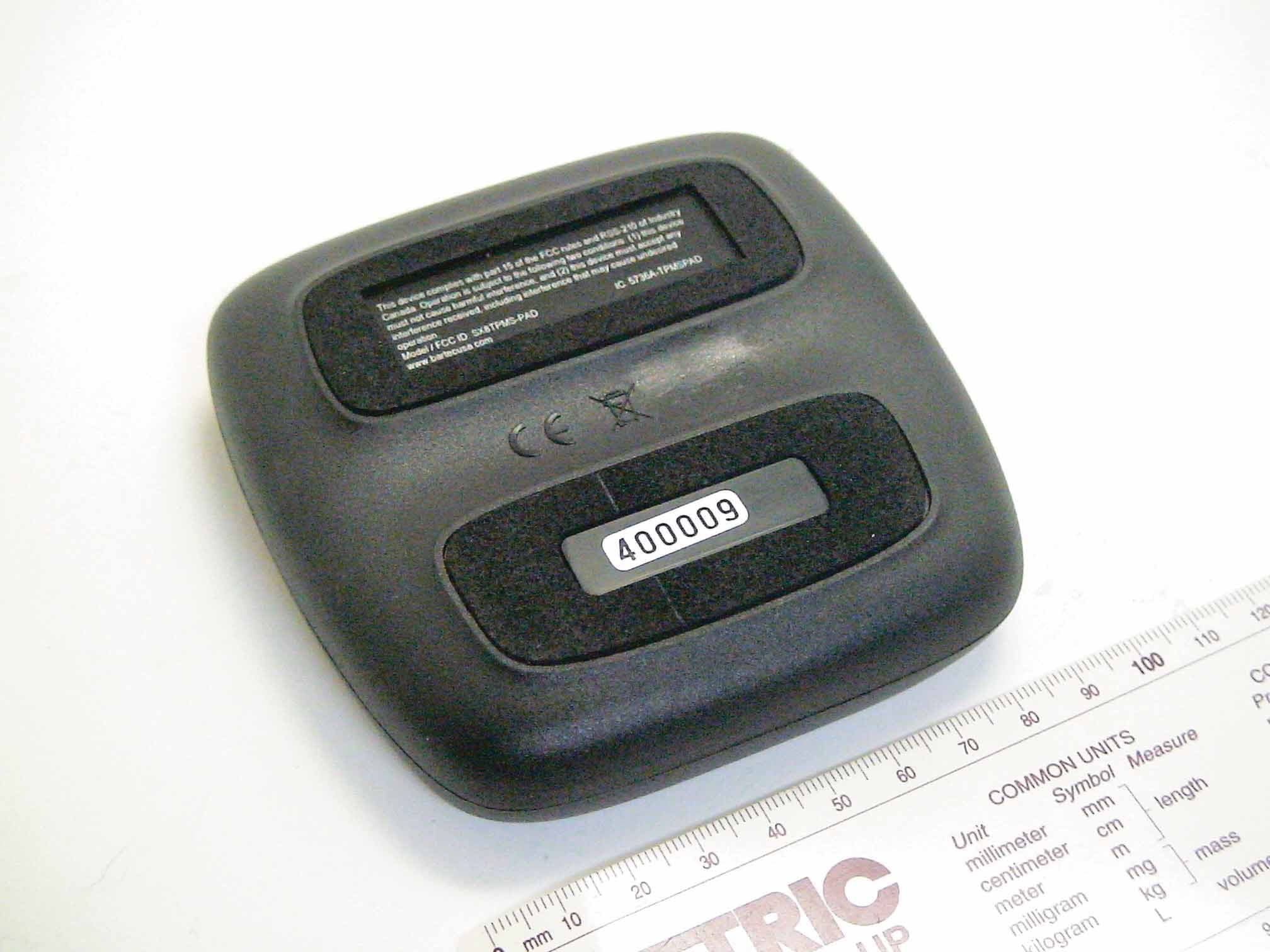
Click to zoom
Application Details
- Equipment Class
- DCD - Part 15 Low Power Transmitter Below 1705 kHz
- Date of Grant
- Oct 13, 2011
- Application Purpose
- Original Equipment
- Date of Application
- Oct 13, 2011
- Equipment Note
- Tire Pressure Programming Transmitter
- Frequency Range
- 0.12500000 - 0.12500000
- Company
- Bartec USA LLC.
- Country
- United States
Documents & Files
Document Text
Text extracted from the exhibit documents filed with the FCC. Open a document above to read the original.
Users Manual
TPMS PAD USER MANUAL Important information Do not discard. Retain for future reference Model / FCC ID: SX8TPMS-PAD IC: 5736A-TPMSPAD This device complies with Part 15 of the FCC Rules and with Industry Canada license-exempt RSS standard(s). Operation is subject to the following two conditions: (1) This device may not cause harmful interference, and (2) This device must accept any interference received, including interference that may cause undesired operation. Le présent appareil est conforme aux CNR d'Industrie Canada applicables aux appareils radio exempts de licence. L'exploitation est autorisée aux deux conditions suivantes : (1) l'appareil ne doit pas produire de brouillage, et (2) l'utilisateur de l'appareil doit accepter tout brouillage radioélectrique subi, même si le brouillage est susceptible d'en compromettre le fonctionnement. Note: Changes or modifications not expressively approved by the party responsible for compliance could void the user's authority to operate the equipment. Note: This equipment has been tested and found to comply with the limits for a Class A digital device, pursuant to Part 15 of the FCC Rules. These limits are designed to provide reasonable protection against harmful interference when the equipment is operated in a commercial environment. This equipment generates, uses, and can radiate radio frequency energy and, if not installed and used in accordance with the instruction manual, may cause harmful interference to radio communications. Operation of this equipment in a residential area is likely to cause harmful interference in which case the user will be required to correct the interference at their expense. WARNING: This product emits electronically generated electromagnetic waves that may interfere with the safe operation of pacemakers. Individuals that have pacemakers should never use this product. READ THESE INSTRUCTIONS BEFORE USING 1. Read All Instructions All warnings in this manual should be adhered to. All operating and use instructions should be followed. 2. Retain Instructions The safety and operating instructions should be retained for future use. 3. Follow Instructions All operating and use instructions should be followed. In particular, the TPMS-PAD is not intended to be used to diagnose TPMs still fitted inside a tyre. The TPM must be removed from the wheel before it can be tested on the TPMS-PAD. 4. Cleaning Clean with a soft dry cloth, or if necessary, a soft damp cloth. Do not use any harsh chemical solvents such as acetone, paint thinner, brake cleaner, alcohol, etc as this may damage the plastic surface. 5. Water & Moisture Do not use this unit where contact or immersion in water is a possibility. Never spill liquid of any kind onto the tool. 6. Storage Do not use or store the tool in an area where it is exposed to direct sunlight or excessive moisture. 7. Use To reduce the risk of fire, do not operate the unit in the vicinity of open containers or flammable liquids. Do not use where the potential for explosive gas or vapours exist. Keep the tool away from heat generating sources. Do not attempt to open the unit. There are no user serviceable parts inside. Introduction The TPMS PAD is a small electronic device which allows a user to test TPMs and also program the Schrader EZSensor. The PAD can only test TPMs which have been removed from a wheel. TPM sensors work by transmitting radio signals from the individual wheels to the vehicle with information about the pressure and temperature of the wheel. This is normally done on a regular basis every few minutes and, on some sensors, more often when the vehicle is moving or if the TPM detects a pressure leak. So that the vehicle only picks up its own signals, the TPM has a serial number which is known by the vehicle. This serial number is programmed into the vehicle at manufacture time and (on most vehicles) when a TPM is replaced. This programming is normally referred to a ‘re-learn’ procedure and often requires the use of a TPM tool such as Bartec’s Tech 400. The Schrader EZSensor is a programmable TPM which can be programmed to exactly emulate the operation of the sensors originally fitted to the car. This means that only two types of EZSensors (315MHz and 433MHz) are needed to replace one of the over 140 TPM sensor types in the market. Another advantage of the EZSensor is that it can be programmed with the same serial number as the broken sensor which means the vehicle does not need to re-learn a new sensor. In addition, copies of existing TPM sensors can be made for winter tyre sets which do not need any user intervention of the vehicle to make them work. The PAD connects to a PC using USB. The pad takes its power from the USB and does not require batteries. A program needs to be installed on the PC which enables the pad to be used. It’s not necessary to install any separate USB driver software to use the PAD. The PAD has a flat surface on the top surrounded by a rim upon which a TPM can be placed. There is a marked area on the top surface where the body of the TPM should be placed. The PAD is not guaranteed to work if the TPM is not placed in this area. A TPM is tested by placing it on the pad, and the PAD generates a magnetic field which causes the TPM to transmit at UHF. If the TPM is non- functional, then the test process will fail. There are no controls on the PAD. The only indicator on the PAD is a multicolour LED which can illuminate in any combination of red, green and blue light. When the PC runs the PAD program and the PAD is connected, it gets a list of supported vehicles from the PAD. The available vehicles can be selected by using the mouse to click on the desired make, model and year. Note that it is the PAD has the list of vehicles contained in an internal database in its firmware. Firmware is like software but is stored on the PAD in flash memory unlike software which is stored on a CD ROM or a disk drive. This means that when updates become available, the firmware on …
Text truncated - open the document above for the full version.
Cover Letter(s)
September 30, 2011 Federal Communications Commission Equipment Approval Services P.O. Box 358315 Pittsburgh, PA 15251-5315 Re: Certification for Bartec Transceiver Model/PN(s): SX8TPMS-PAD FCC ID: SX8TPMS-PAD IC: 5736A-TPMSPAD Please find enclosed application materials for certification of Bartec Transceiver. We tested it and found it to comply with FCC Part 15. If there are any questions regarding the application or testing performed, please contact me at the above address or call 734-483-4211, fax 734-647-2106, or e-mail [email protected]. Sincerely, Valdis V. Liepa Research Scientist
Cover Letter(s)
Re: Certification for Bartec Transceiver FCC ID: SX8TPMS-PAD IC: 5736A-TPMSPAD REQUEST FOR CONFIDENTIALITY Pursuant to FCC 47 CRF 0.457(d) and 0.459 and IC RSP-100, Section 10, Bartec requests that a part of the subject application be held confidential. Bartec has spent substantial effort in developing this product and it is one of the first of its kind in industry. Having the subject information easily available to "competition" would negate the advantage they have achieved by developing this product. Not protecting the details of the design will result in financial hardship. Type of Confidentiality Requested Exhibit Short Term Permanent (1) ID Label & Location Short Term Permanent (3) External Photos Short Term Permanent 1 (4) Block Diagram Short Term Permanent (5) Schematics Short Term Permanent (7) Test Setup Photos Short Term Permanent (8) User’s Manual Short Term Permanent (9) Internal Photos Short Term Permanent (10) Parts List & Placement Short Term Permanent (11) RF Exposure Short Term Permanent 2 (12) Description of Operation (partial) 1. Block Diagram includes internal oscillator frequency information that the manufacturer considers to be proprietary. 2. The modes of operation for this device contain information that the manufacturer considers to be proprietary. Permanent Confidentiality: Bartec requests the exhibits listed above as permanently confidential be permanently withheld from public review. Short-Term Confidentiality (FCC Only): Bartec requests the exhibits selected above as short term confidential be withheld from public view for a period of 45 days from the date of the Grant of Equipment Authorization and prior to marketing. If there are any questions regarding this request, please contact me at the above address or call 734-483-4211, fax 734-647-2106 or e-mail [email protected]. Sincerely, Valdis V. Liepa, Research Scientist University of Michigan
Operational Description
Bartec Auto ID Ltd TPMS PAD Description and theory of operation Author C Beal, Bartec Auto Id Ltd Date 28 July 2011 Version 1.0 Description The TPMS PAD is a small electronic device which allows a user to test TPMs and also program the Schrader EZSensor. The PAD enclosure is made from ABS plastic approximately 100mm * 100mm * 25mm (42” * 4” * 0.5”). It contains a single PCB containing a 125KHz magnetic field generator and a programmable UHF receiver. It has a flat surface on the top surrounded by a rim upon which a TPM can be placed. There is a marked area on the top surface where a TPM should be placed. The PAD is not guaranteed to work if the TPM is not placed in this area. A TPM is tested by placing it on the pad, and the PAD generates a 125KHz magnetic field which causes the TPM to transmit at UHF. The magnetic field generated is in the range 1nT to 1uT. There are no controls on the PAD. The only indicator on the PAD is a multicolour LED which can illuminate in any combination of red green and blue light. The PAD uses an ARM Cortex M3 microprocessor running at 72MHz maximum clock rate. This rate is derived from an 8MHz crystal by means of an on-chip PLL. There is 512KB FLASH memory on the processor which is used for storage of program code and data tables. The LF transmitter uses an H-bridge MOSFET arrangement and two ferrite cored coils which are tuned using a switched capacitor array to resonate at 125KHz. The 125KHz drive signal to the H- bridge comes directly from the microprocessor and is derived from the 8MHz crystal. The UHF receiver is a programmable multiband single-chip receiver which is programmed using a 3- wire SPI bus. This uses a 26MHz crystal and on-chip PLL to generate its internally used clocks. The PAD connects to a PC using USB. The connector on the PAD is a miniature B type. The USB 5V power is used by the PAD and the current used is normally less than 100mA. The USB speed is Full Speed i.e. 12Mbps. The communications class is Human Interface Device (HID) so the PAD looks like a keyboard or mouse to the PC. This is so that the PC doesn’t require a device driver. The PC runs a program which provides the user interface and tells the PAD what type of TPM to test. The PAD contains a list of available TPMs which the PC program requests when the PC program starts. Operation The PAD is connected to the PC using a standard USB cable. When the PC program starts, the user clicks on a button to display the available vehicle makes. This sends a command via USB to the PAD which responds with the available vehicle makes, models and years that the PAD has in its internal data tables. The user can then choose a make model and year of vehicle which sends a command to the PAD to select the appropriate TPM type. The user can then choose to test the TPM normally fitted to that vehicle or alternatively to generate a copy of the TPM by programming a Schrader EZSensor. When the test or program process starts, the LED changes colour to indicate testing is in progress. During testing or programming, the PAD generates a 125KHz magnetic field in order to communicate with the TPM. The PAD sets the UHF receiver parameters to those appropriate to that type of TPM and decodes the received UHF data. The operation can take up to one or two minutes depending on the TPM type. If the test is successful, the LED illuminates green. If not, the LED illuminates red. At the same time, the PAD sends a response via USB to the PC which displays the results on the screen.
Test Report
University of Michigan Radiation Laboratory FCC Part 15, IC RSS-210/Gen - Test Report No. 417124-613 Page 1 of 13 The University of Michigan Radiation Laboratory 3228 EECS Building Ann Arbor, MI 48109-2122 Tel: (734) 764-0500 Fax: (734) 647-2106 Measured Radio Frequency Emissions From Bartec USA LLC Transceiver FCC ID: SX8TPMS-PAD IC: 5736A-TPMSPAD Test Report No. 417124-613 September 30, 2011 Copyright © 2011 For: Bartec USA LLC 44231 Phoenix Drive Sterling Heights, MI 48314 Contact: Scot Holloway [email protected] Phone: 586 -685 -1300 Fax: 586-323-3801 Testing supervised by: Measurements made by: Joseph D. Brunett Report Approved by:__________________________ Valdis V. Liepa Test report written by: Joseph D. Brunett Research Scientist Summary Tests for compliance with FCC Regulations, CFR 47, Part 15 and with Industry Canada RSS-210/Gen, were performed on a Bartec, FCC ID: SX8TPMS-PAD, IC: 5736A-TPMSPAD. This device under test (DUT) is subject to the rules and regulations as a Transceiver. In testing completed on Septe mb er 25, 2011, the DUT tested met the allowed specifications for radiated emissions by more than 0.2 dB. AC Mains conducted emissions met the regulatory limit by 7. 2 dB. University of Michigan Radiation Laboratory FCC Part 15, IC RSS-210/Gen - Test Report No. 417124-613 Page 2 of 13 Table of Contents 1. Introduction ...................................................................................................................................... 3 2. Equipment Used ............................................................................................................................... 3 3. Device Under Test ........................................................................................................................... 4 3.1 Description & Block Diagram .............................................................................................. 4 3.2 Samples & Variants ............................................................ Error! Bookmark not defined. 3.3 Modes of Operation .............................................................................................................. 4 3.4 Exemptions ........................................................................................................................... 4 3.5 EMC Relevant Modifications ............................................................................................... 4 4. Emissions Limits .............................................................................................................................. 5 4.1 Radiated Emissions Limits .................................................................................................... 5 5. Measurement Procedures ................................................................................................................. 6 5.1 Semi -Anechoic Chamber Radiated Emissions ...................................................................... 6 5.2 Outdoor Radiated Emissions ................................................................................................. 6 5.3 Radiated Field Computations ................................................................................................ 6 5.4 Indoor Power Line Conducted Emissions ............................................................................. 6 5.5 Supply Voltage Variation ...................................................................................................... 7 6. Test Results ...................................................................................................................................... 7 6.1 Radiated Emissions ............................................................................................................... 7 6.1.1 Correction for Pulse Operation ......................................................................................... 7 6.1.2 Emission Spectrum ........................................................................................................... 7 6.1.3 Emission Bandwidth ......................................................................................................... 7 6.1.4 Supply Voltage and Supply Voltage Variation ................................................................. 7 6.2 Conducted Emissions ............................................................................................................ 7 University of Michigan Radiation Laboratory FCC Part 15, IC RSS-210/Gen - Test Report No. 417124-613 Page 3 of 13 1. Introduction This Bartec Transceiver was tested for compliance with FCC Regulations, Part 15, adopted under Docket 87-389, April 18, 1989 as subsequently amended, and with Industry Canada RSS-210/Gen, Issue 10, December 2010. T ests were performed at the University of Michigan Radiation Laboratory Willow Run Test Range following the procedures described in ANSI C63.4-2003 "Methods of Measurement of Radio- Noise Emissions from Low-Voltage Electrical and Electronic Equipment in the Range of 9 kHz to 40 GHz". The Site description and attenuation characteristics of the Open Site facility are on file with FCC Laboratory, Columbia, Maryland (FCC Reg. No: 91050) and with Industry Canada, Ottawa, ON (File Ref. No: IC 2057A-1). 2. Equipment Used The test equipment commonly used in our facility is listed in Table 2.1. Except where indicated as a pre- test, monitoring, or support device; all equipment listed below is a part of the University of Michigan Radiation Laboratory (UMRL) quality system. This quality system has been established to ensure all equipment has a clearly identifiable classification, calibration expiry date, and that all calibrations are traceable to national standards. Table 2.1 Test Equipment. Test Instrument Used Manufacturer/Model Q Number Spectrum Analyzer (9kHz-26GHz) Hewlett-Packard 8593E, SN: 3412A01131 HP8593E1 Spectrum Analyzer (9kHz-6.5GHz) Hewlett-Packard 8595E, SN: 3543A01546 JDB8595E Power Mete…
Text truncated - open the document above for the full version.
Contact Information
Applicant
Scot A. Holloway(General Manager)
Technical Contact
University of Michigan/EECSValdis V. Liepa
[email protected]734-483-4211
1301 Beal Avenue · Ann Arbor, Michigan · United States
Test Firm
University of MichiganValdis Liepa
Technical Specifications
| # | Rule Parts | Frequency Range | Power Output |
|---|---|---|---|
| 1 | 15C | 0.125 MHz - 0.125 MHz | - |
Other Applications from Bartec USA LLC.
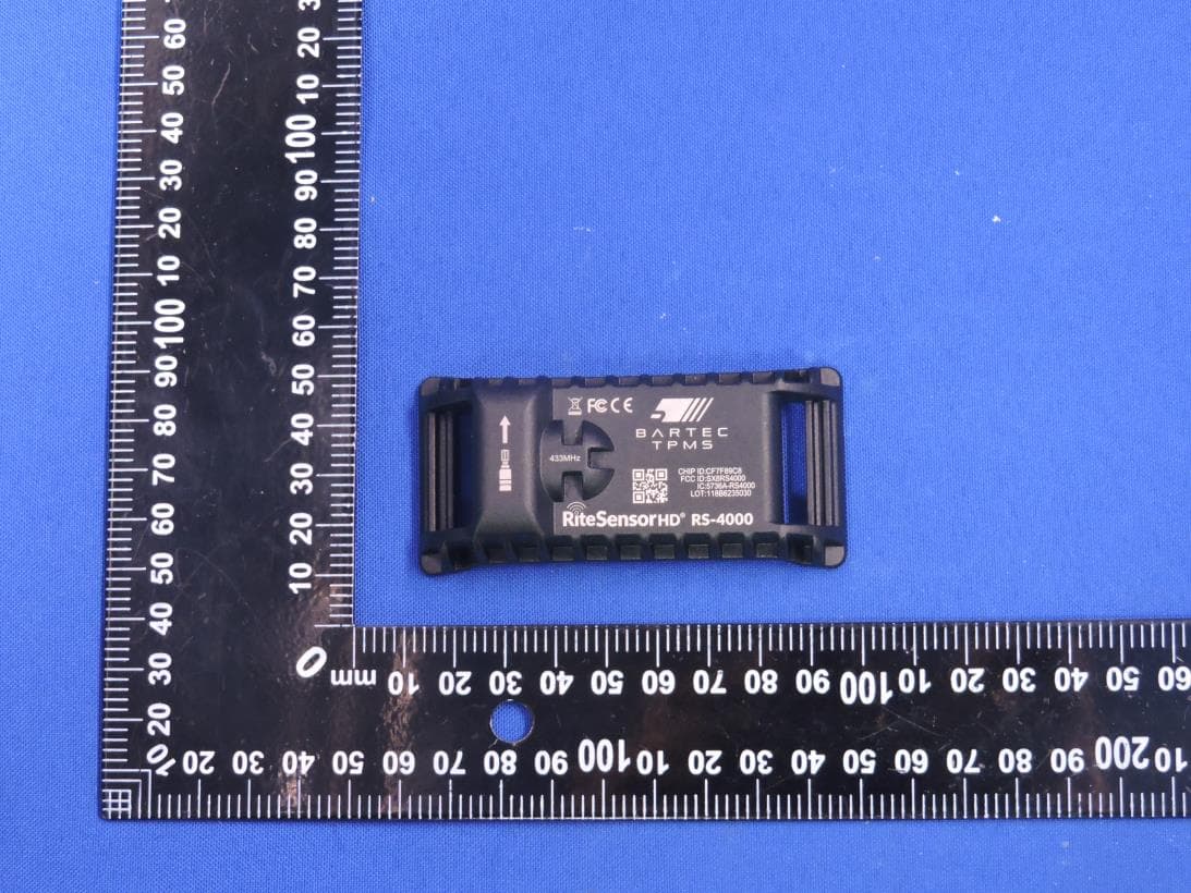
SX8RS4000
Mar 23, 2026Rite Sensor HD
Equipment Class
DSC - Part 15 Security/Remote Control Transmitter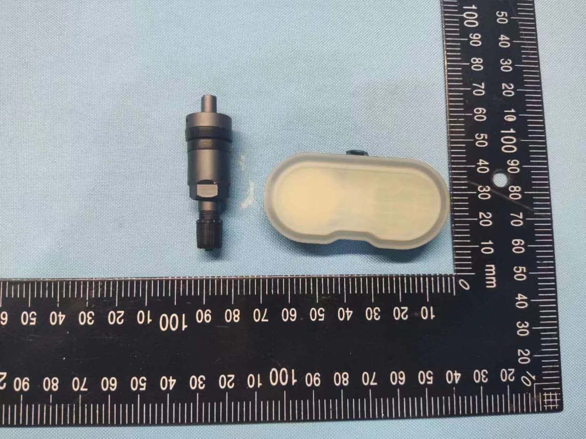
SX8-RS3000
Sep 21, 2022RITE-SENSOR BlueR
Equipment Class
DTS - Digital Transmission System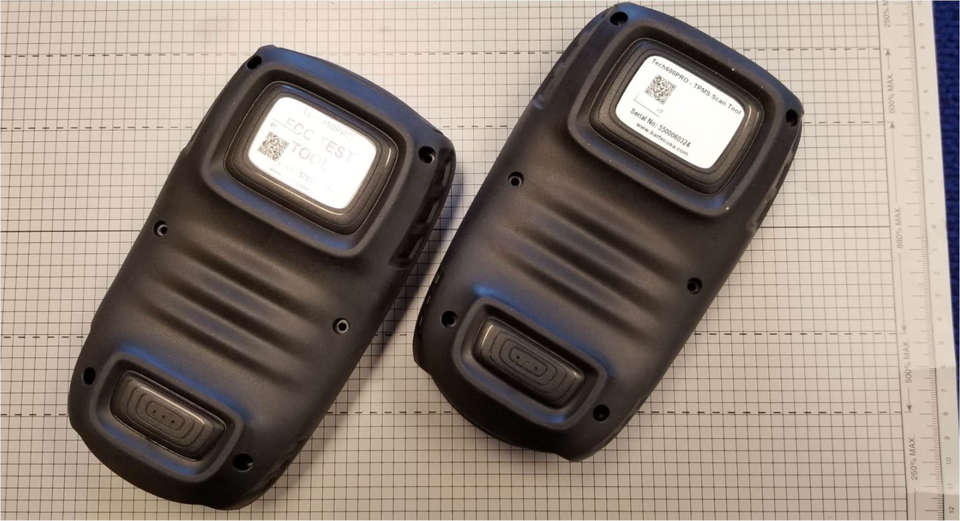
SX8DSW9
May 20, 2021LF TRANSMITTER
Equipment Class
DCD - Part 15 Low Power Transmitter Below 1705 kHz
SX8T500
Jul 08, 2013Tire Pressure Monitoring System Test Transmitter
Equipment Class
DCD - Part 15 Low Power Transmitter Below 1705 kHz
SX8-DSW
Mar 29, 2008Tire Pressure Sensor Diagnostic Tool
Equipment Class
DCD - Part 15 Low Power Transmitter Below 1705 kHz