SX8-DEGTPMS Receiver
Bartec USA LLC.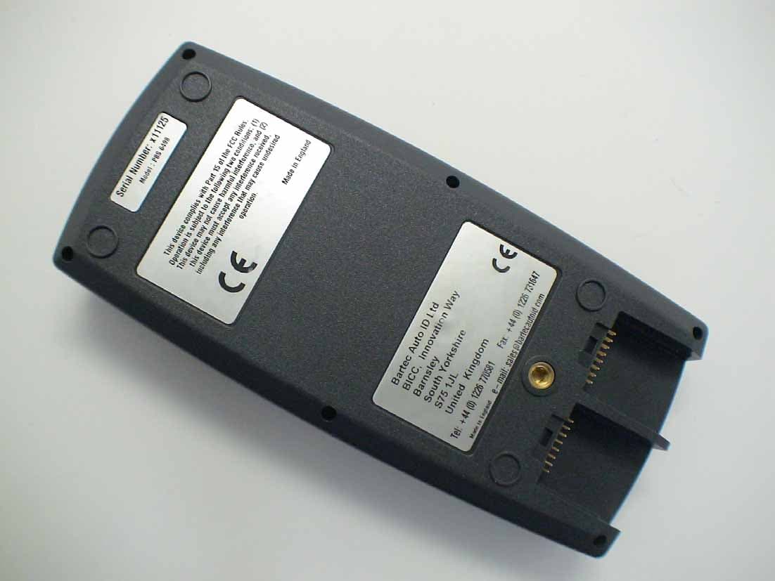
Click to zoom
Application Details
- Equipment Class
- CYY - Communications Receiver used w/Pt 15 Transmitter
- Date of Grant
- May 11, 2006
- Application Purpose
- Original Equipment
- Date of Application
- May 10, 2006
- Equipment Note
- TPMS Receiver
- Frequency Range
- 433.92000000 - 433.92000000
- Company
- Bartec USA LLC.
- Country
- United States
Documents & Files
Document Text
Text extracted from the exhibit documents filed with the FCC. Open a document above to read the original.
Users Manual
Re: Certification for Bartec Composite Device Model(s): SX8-DEG FCC ID: SX8-DEG IC: 5736A-DEG USER'S MANUAL INFORMATION (PRELIMINARY) The User's Manual is in preparation. The following material will be contained in the manual: FCC ID: SX8-DEG IC: 5736A-DEG This device complies with Part 15 of the FCC Rules and with RSS-210 of Industry Canada. Operation is subject to the following two conditions: (1) This device may not cause harmful interference, and (2) This device must accept any interference received, including interference that may cause undesired operation. WARNING: Changes or modifications not expressively approved by the party responsible for compliance could void the user's authority to operate the equipment. The term “IC:” before the radio certification number only signifies that Industry Canada technical specifications were met.
Attestation Statements
Re: Certification for Bartec Composite Device Model(s): SX8-DEG FCC ID: SX8-DEG IC: 5736A-DEG POWER OF ATTORNEY A letter granting Valdis V. Liepa the Power of Attorney is on file and can be provided when so requested. Re: Certification for Bartec Composite Device Model(s): SX8-DEG FCC ID: SX8-DEG IC: 5736A-DEG REQUEST FOR CONFIDENTIALITY Pursuant to 47 CRF 0.459, Bartec requests that a part of the subject application be held confidential. This comprises Exhibits (5) Schematics (10) Parts List (Part of Exhibit only) Bartec has spent substantial effort in developing this product and it is one of the first of its kind in industry. Having the subject information easily available to "competition" would negate the advantage they have achieved by developing this product. Not protecting the details of the design will result in financial hardship. If there are any questions regarding this request, please contact me at the above address or call 734-483-4211, fax 734-647-2106 or e-mail [email protected]. Sincerely, Valdis V. Liepa Research Scientist University of Michigan May 6, 2006 Re: Certification for Bartec Composite Device Model(s): SX8-DEG FCC ID: SX8-DEG IC: 5736A-DEG STATEMENT OF MODIFICATIONS There were no modifications made to the DUT by this test laboratory. (Also see Section 3.1 of the attached Test Report). _____________________ Valdis V. Liepa Research Scientist Re: Certification for Bartec Composite Device Model(s): SX8-DEG FCC ID: SX8-DEG IC: 5736A-DEG GENERAL PRODUCT INFORMATION The device, for which certification is pursued, has been designed by: Bartec USA LLC 44231 Phoenix Drive Sterling Heights, MI 48314 Scot Holloway Tel: 586-685-1300 Fax: 586-323-3801 It will be manufactured by: Bartec USA LLC 44231 Phoenix Drive Sterling Heights, MI 48314 Scot Holloway Tel: 586-685-1300 Fax: 586-323-3801 Canadian Contact: Not Yet Avaliable
Cover Letter(s)
May 6, 2006 Federal Communications Commission Equipment Approval Services P.O. Box 358315 Pittsburgh, PA 15251-5315 Re: Certification for Bartec Composite Device Model(s): SX8-DEG FCC ID: SX8-DEG IC: 5736A-DEG Please find enclosed application materials for certification of Bartec SX8-DEG Composite Device. We tested it and found it to comply with FCC Part 15. If there are any questions regarding the application or testing performed, please contact me at the above address or call 734-483-4211, fax 734-647-2106, or e-mail [email protected]. Sincerely, Valdis V. Liepa Research Scientist May 6, 2006 Certification and Engineering Bureau Industry Canada 3701 Carling Avenue, Bldg. 94 Ottawa, Ontario K2H 8S2 Re: Certification for Bartec Composite Device Model(s): SX8-DEG FCC ID: SX8-DEG IC: 5736A-DEG Please find enclosed application materials for certification of Bartec SX8-DEG Composite Device. We tested the device and found it to comply with RSS- GEN/102/210. The product is identified by: IC: 5736A-DEG If there are any questions, suggestions, etc., regarding the application or testing performed, please contact me at the above address or call 734-483-4211, fax 734-647- 2106; e-mail: [email protected]. Sincerely, Valdis V. Liepa Research Scientist
Cover Letter(s)
May 6, 2006 American Telecommunications Certification Body, Inc. 6731 Whittier Avenue Suite C110 McLean, VA 22101 RE: Certification Application FCC ID: SX8-DEG IC: 5736A-DEG Model(s): SX8-DEG Please find enclosed application materials for certification of Bartec SX8-DEG Composite Device. Note: 1) portions of this submittal are filed Confidential 2) a list of the modifications made is provided in Attestations. If there are any questions regarding the application or testing performed, please contact me at the above address or call 734-483-4211, fax 734-647-2106, or e-mail [email protected]. Sincerely, Valdis V. Liepa Research Scientist
Operational Description
BARTEC USA 6543 ARROW DRIVE STERLING HEIGHTS , MI 48314 Phone (586) 685-1300 Fax (586) 323-3801 DEG Provisional Data DESIGN and SPECIFICATION The DEG is a rugged test tool for tyre pressure monitoring devices (TPMs), designed specifically for the workshop environment. Simple to use, the main functions are operated with large keys and a friendly on-screen menu enables easy set-up. The DEG enables the operator to activate a TPM, identify that the TPM has transmitted a response, decodes the data and displays such information as identification code, pressure, temperature, status and type. The hardware supports dual frequencies from a range of TPM suppliers, standard frequencies being 315 and 433.92 MHz. The software architecture is designed to accommodate a library of TPM types with various encoding schemes from a range of TPM suppliers. The DEG has a download capability for updating its TPM database. This facilitates the continuing introduction to the market of new TPM devices with specific encoding algorithms. The DEG’s serial communication capabilities can also be used to upload captured data for archiving in a host system or for further vehicle diagnostic applications. Although the standard tool is described in this document, the design has been developed with customisation in mind and variations can be incorporated in customised badged units to special order. TECHNICAL SPECIFICATION Processor: Toshiba TPM95FY64P Processor running at 20 MHz. Display: STN LCD fitted with electro-luminescent backlight panel switched under software control. The pixel format is 128 by 64. This provides 8 lines of 20 characters in standard text mode but optional formats in full graphics mode (as defined by the application program). Display aperture 58 mm wide by 40 mm high. The display is internally protected by a shock resistant rubber mounting. BARTEC USA 6543 ARROW DRIVE STERLING HEIGHTS , MI 48314 Phone (586) 685-1300 Fax (586) 323-3801 Keyboard: 11 button keyboard as standard. Tactile feedback provided by the metal dome technology over printed with 14 mm square box to include printed function text. Audible feedback provided by buzzer mounted inside the unit housing. One key defined for on/off function supported with software time-out from last activity. Battery: 1800 mAh Nickel Metal Hydride pack. High speed temperature controlled charge capability from 12 volt supply (1.25 amp minimum). Interface: USB port and serial ASCII dependant on cable or connector option. LF activation: 125 KHz with duration and modulation software controlled in accordance with TPM type. Field strength also software controlled in accordance to TPM type. UHF reception: 315 MHz and 433.92 MHz software selected in accordance to TPM type. PHYSICAL SPECIFICATION Enclosure: Made from Xenoy 5730 composite polymer in dark grey. There is an optional rubber outer case to provide additional drop resistance to 1.2 meters onto a hard surface. Size (without rubber protection cover): 206 mm Long (8.11 inches) 95 mm Wide (3.75 inches) 50 mm Deep (1.97 inches) Weight: 570 grams without rubber protection cover (20 ounces) 810 grams with rubber protection cover (28.5 ounces) ENVIRONMENTAL SPECIFICATION Operating temperature 0º C to 50º C (32º F to 122º F) Storage temperature -20º C to 55º C (–4º to 131º F) Issue C Dated 3 rd June 2005 TMA
Test Report
University of Michigan Radiation Laboratory FCC Part 15, IC RSS-210/Gen - Test Report No. 415031-291 Page 1 of 11 The University of Michigan Radiation Laboratory 3228 EECS Building Ann Arbor, MI 48109-2122 Tel: (734) 764-0500 Measured Radio Frequency Emissions From Bartec Composite Device 315/433 MHz Receiver Test Report Model(s): SX8-DEG Report No. 415031-291 May 6, 2006 Copyright © 2006 For: Bartec USA LLC 44231 Phoenix Drive Sterling Heights, MI 48314 Contact: Scot Holloway Tel: 586-685-1300 Fax: 586-323-3801 Tests supervised by: Measurements made by: Report approved by: _____________________ Joseph D. Brunett Valdis V. Liepa Research Scientist Summary Tests for compliance with FCC Regulations Part 15, Subpart B, and Industry Canada RSS-210/GEN, were performed on Bartec composite device model SX8-DEG. This device is subject to the Rules and Regulations as a Receiver. In testing completed on April 25, 2006, the device tested in the worst case met the allowed Class B specifications for radiated emissions by 9.7 dB (see p. 6). The device meets FCC/IC Class B power line conducted emissions limits by 10.2 dB (see p. 7). University of Michigan Radiation Laboratory FCC Part 15, IC RSS-210/Gen - Test Report No. 415031-291 Page 2 of 11 1. Introduction Bartec USA LLC model SX8-DEG was tested for compliance with FCC Regulations, Part 15, adopted under Docket 87-389, April 18, 1989, and with Industry Canada RSS-210, Issue 6 and RSS-Gen, Issue 1, September, 2005. The tests were performed at the University of Michigan Radiation Laboratory Willow Run Test Range following the procedures described in ANSI C63.4-2003 "Methods of Measurement of Radio-Noise Emissions from Low-Voltage Electrical and Electronic Equipment in the Range of 9 kHz to 40 GHz". The Site description and attenuation characteristics of the Open Site facility are on file with FCC Laboratory, Columbia, Maryland (FCC Reg. No: 91050) and with Industry Canada, Ottawa, ON (File Ref. No: IC 2057). 2. Test Procedure and Equipment Used The pertinent test equipment commonly used in our facility for measurements is listed in Table 2.1 below. The middle column identifies the specific equipment used in these tests. Table 2.1 Test Equipment. Test Instrument Eqpt. Used Manufacturer/Model Spectrum Analyzer (0.1-1500 MHz) Hewlett-Packard, 182T/8558B Spectrum Analyzer (9kHz-22GHz) X Hewlett-Packard 8593A SN: 3107A01358 Spectrum Analyzer (9kHz-26GHz) X Hewlett-Packard 8593E, SN: 3412A01131 Spectrum Analyzer (9kHz-26GHz) Hewlett-Packard 8563E, SN: 3310A01174 Spectrum Analyzer (9kHz-40GHz) Hewlett-Packard 8564E, SN: 3745A01031 Power Meter Hewlett-Packard, 432A Power Meter Anritsu, ML4803A/MP Harmonic Mixer (26-40 GHz) Hewlett-Packard 11970A, SN: 3003A08327 Harmonic Mixer (40-60 GHz) Hewlett-Packard 11970U, SN: 2332A00500 Harmonic Mixer (75-110 GHz) Hewlett-Packard 11970W, SN: 2521A00179 Harmonic Mixer (140-220 GHz) Pacific Millimeter Prod., GMA, SN: 26 S-Band Std. Gain Horn S/A, Model SGH-2.6 C-Band Std. Gain Horn University of Michigan, NRL design XN-Band Std. Gain Horn University of Michigan, NRL design X-Band Std. Gain Horn S/A, Model 12-8.2 X-band horn (8.2- 12.4 GHz) Narda 640 X-band horn (8.2- 12.4 GHz) Scientific Atlanta , 12-8.2, SN: 730 K-band horn (18-26.5 GHz) FXR, Inc., K638KF Ka-band horn (26.5-40 GHz) FXR, Inc., U638A U-band horn (40-60 GHz) Custom Microwave, HO19 W-band horn(75-110 GHz) Custom Microwave, HO10 G-band horn (140-220 GHz) Custom Microwave, HO5R Bicone Antenna (30-250 MHz) X University of Michigan, RLBC-1 Bicone Antenna (200-1000 MHz) X University of Michigan, RLBC-2 Dipole Antenna Set (30-1000 MHz) X University of Michigan, RLDP-1,-2,-3 Dipole Antenna Set (30-1000 MHz) EMCO 2131C, SN: 992 Active Rod Antenna (30 Hz-50 MHz) EMCO 3301B, SN: 3223 Active Loop Antenna (30 Hz-50 MHz) EMCO 6502, SN:2855 Ridge-horn Antenna (300-5000 MHz) X University of Michigan Amplifier (5-1000 MHz) X Avantak, A11-1, A25-1S Amplifier (5-4500 MHz) X Avantak Amplifier (4.5-13 GHz) Avantek, AFT-12665 Amplifier (6-16 GHz) Trek Amplifier (16-26 GHz) Avantek LISN Box University of Michigan Signal Generator X Hewlett-Packard 8657B University of Michigan Radiation Laboratory FCC Part 15, IC RSS-210/Gen - Test Report No. 415031-291 Page 3 of 11 3. Configuration and Identification of Device Under Test The DUT is a composite device consisting of a 315 MHz transmitter, a 433 MHz transmitter, a 125 kHz transmitter, a 315 MHz receiver, and a 433 MHz receiver. This report details the emissions relating to the 315 MHz and 433 MHz receiver portion of the device. The 315MHz superheterodyne receiver uses a 10 MHz reference, with LO at 325.7 MHz mixed down from 2xLO at 651.4 MHz on chip. The 433.92 MHz superheterodyne receiver uses a 13 MHz reference, with LO at 423.2 MHz mixed down from 2xLO at 846.4 MHz on chip. The antennas are integral, wires attached to the receiver modules. The device is 4 x 8 x 1.5 inches in size. The DUT was designed and manufactured by Bartec, 44231 Phoenix Drive,Sterling Heights, MI 48314. It is identified as:It is identified as: Bartec DEG LF Transmitter Model: SX8-DEG FCC ID: SX8-DEG IC: 5736A-DEG 3.1 Modifications Made There were no modifications made to the DUT by this laboratory. 4. Emission Limits The DUT tested falls under Part 15, Subpart B, "Unintentional Radiators". The pertinent test frequencies, with corresponding emission limits, are given in Tables 4.1 and 4.2 below. 4.1 Radiated Emission Limits Table 4.1. Radiated Emission Limits (Ref: FCC 15.33, 15.35, and 15.109; IC RSS-210, 2.6 Table 2). Freq. (MHz) E lim (3m) μV/m E lim (3m) dB(μV/m) 30-88 100 40.0 88-216 150 μV/m 43.5 216-960 200 μV/m 46.0 960-2000 500 μV/m 54.0 Note: Quasi-Peak readings apply to 1000 MHz (120 kHz BW) Average readings apply above 1000 MHz (1 MHz BW) University of Michigan Radiation Laboratory FCC Part 15, IC RSS-210/Gen - Test Report No. 415031-291 Page 4 of 11 4.2 Power Line Conducted Emission Limits Table 4.3 Conducted Emission Limits (FCC:15.107 (CISPR)…
Text truncated - open the document above for the full version.
Contact Information
Applicant
Scot A. Holloway(General Manager)
Technical Contact
University of MichiganValdis Liepa
[email protected]734-483-4211
1301 Beal Ave. · Ann Arbor, Michigan · United States
Test Firm
University of MichiganValdis Liepa
Technical Specifications
| # | Rule Parts | Frequency Range | Power Output |
|---|---|---|---|
| 2 | 15B | 433.92 MHz - 433.92 MHz | - |
Other Applications from Bartec USA LLC.
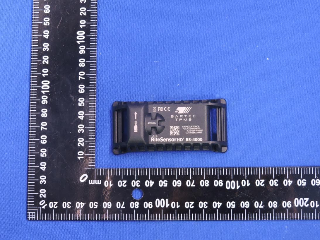
SX8RS4000
Mar 23, 2026Rite Sensor HD
Equipment Class
DSC - Part 15 Security/Remote Control Transmitter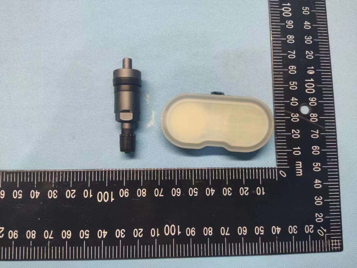
SX8-RS3000
Sep 21, 2022RITE-SENSOR BlueR
Equipment Class
DTS - Digital Transmission System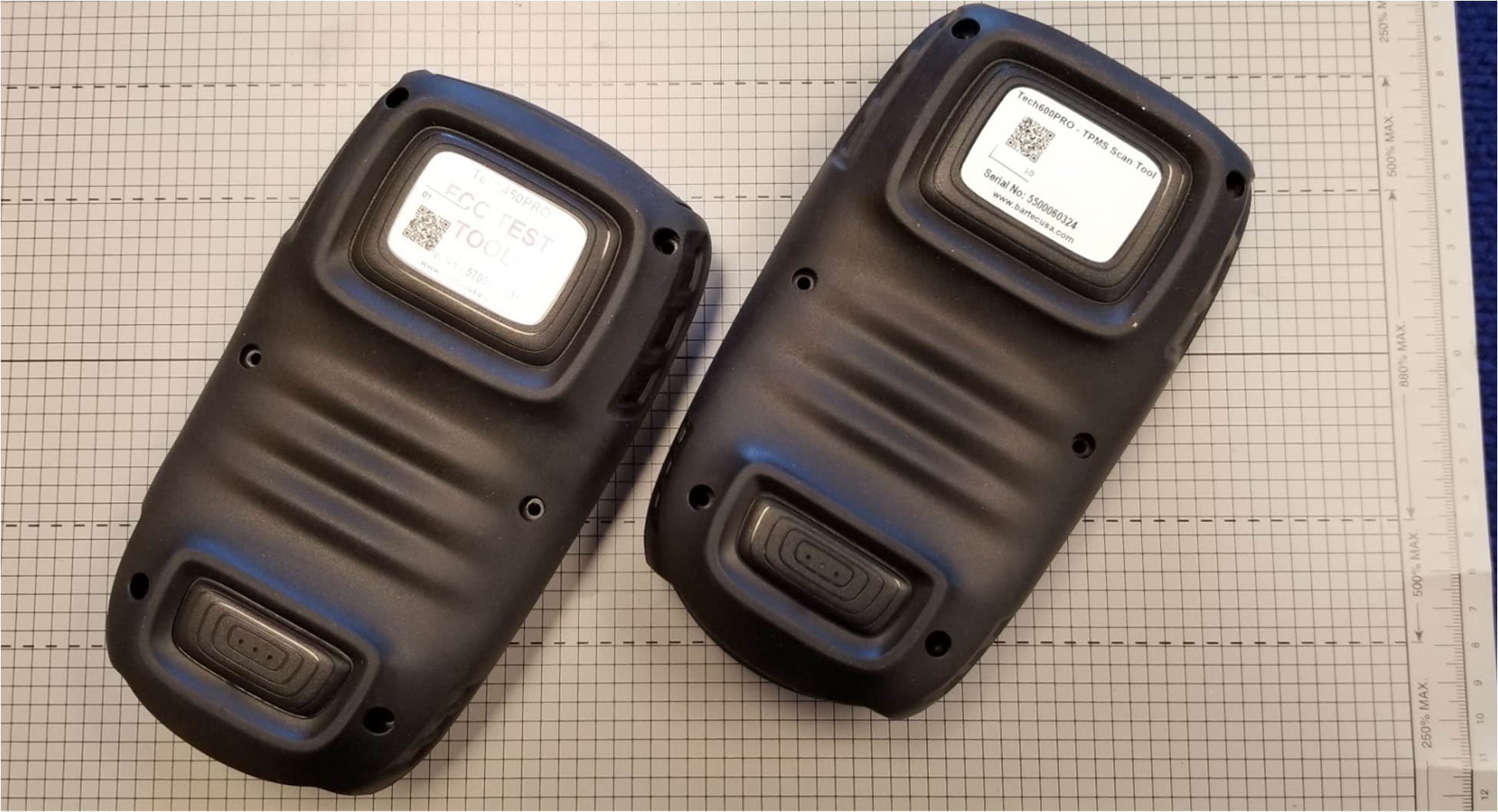
SX8DSW9
May 20, 2021LF TRANSMITTER
Equipment Class
DCD - Part 15 Low Power Transmitter Below 1705 kHz
SX8T500
Jul 08, 2013Tire Pressure Monitoring System Test Transmitter
Equipment Class
DCD - Part 15 Low Power Transmitter Below 1705 kHz
SX8TPMS-PAD
Oct 13, 2011Tire Pressure Programming Transmitter
Equipment Class
DCD - Part 15 Low Power Transmitter Below 1705 kHz