SX8-DSWTire Pressure Sensor Diagnostic Tool
Bartec USA LLC.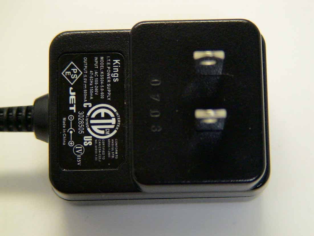
Click to zoom
Application Details
- Equipment Class
- DCD - Part 15 Low Power Transmitter Below 1705 kHz
- Date of Grant
- Mar 29, 2008
- Application Purpose
- Original Equipment
- Date of Application
- Mar 28, 2008
- Equipment Note
- Tire Pressure Sensor Diagnostic Tool
- Frequency Range
- 0.12500000 - 0.12500000
- Company
- Bartec USA LLC.
- Country
- United States
Documents & Files
Document Text
Text extracted from the exhibit documents filed with the FCC. Open a document above to read the original.
Users Manual
TECH400 Tech 400 User Guide R5 4/1/08 28 QUICK REFERENCE GUIDE If necessary, charge by plugging in charger - the unit will power up and show charging status via the battery symbol and charger connected icon. Turn on using lower left ‘on/off’ key Use up and down arrows to select (lighter text on dark background) the required function or menu item. Use ‘Enter’ to select this function Common activities: Set to 4 wheels (use settings menu) to prepare to audit a vehicle. Select by vehicle—first by ma k e, then model, then year. Press Enter key to continue test. In 4 wheel mode- the arrow points to the wheel to be tested Press ‘Test’ to test the TPM. If test passes, arrow automatically points to next wheel. (Or man ually move around vehicle using ‘up’ or ‘down’ keys) Lower part of display provides summary results for each TPM. Where vehicles permit, use ‘up’ or ‘down’ to select vehicle commu nications icon in the audit display. Connect the cable to the OBD interface and plug this into the vehicle. Select required action from the screen. TPM results data can also be vi ewed (in main menu entry item) TPM results data can be accessed (printed) from a pc (connect using USB lead). The provided PC screen audit form can be completed from the pc keyboard. TPM results data can be deleted (main menu item). It is recommended this is done prior to a vehicle audit. Settings (e.g. TPM measurement units) can be altered (main menu item) Home key will always return to the default main menu Turn off using lower left ‘on/off’ key Tech 400 User Guide R5 4/1/08 1 TABLE OF CONTENTS SPECIFICATION/ FUNCTIONALITY 3 PART NAMES AND FUNCTIONS 4 POWER ON/OFF SEQUENCE 5 TEST METHODOLOGY 5 MAIN DISPLAY AREA AND DESCRIPTION 5 RESULTS/ TEST DISPLAY AREA AND DESCRIPTION 10 MENU SYSTEM 11 READING A TPM 18 PC CONNECTION CAPABILITIES 23 VEHICLE COMMUNICATION 25 QUICK REFERENCE GUIDE 28 Tech 400 User Guide R5 4/1/08 2 IMPORTANT NOTICES The contents of this manual may not be reproduced or distributed by any means electronically, mechanically, recording or otherwise. All specifications, illustrations and information contained within this manual are based on the most current information available at the time of publication. Bartec reserves the right to make changes at any time without obligation to notify any person or organization. Bartec will do its best to keep you the customer informed of any changes that might affect the tools performance. FCC Compliance Model: DSW FCC ID: SX8- DSW IC: 5736A-DSW This device complies with part 15 of the FCC rules and with RSS-210 of Industry Canada. Operation is subject to the following two conditions: (1) this device may not cause harmful interference, and (2) this device must accept any interference received, including interference that may cause undesired operation. Changes or modifications not expressly approved by the party responsible for compliance could void the user's authority to operate the equipment. Note: This equipment has been tested and found to comply with the limits for a Class A digital device, pursuant to Part 15 of the FCC Rules. These limits are designed to provide reasonable protection against harmful interference when the equipment is operated in a commercial environment. This equipment generates, uses, and can radiate radio frequency energy and, if not installed and used in accordance with the instruction manual, may cause harmful interference to radiocommunications. Operation of this equipment in a residential area s likely to cause harmful interference in which case the user will be required to correct the interference at their expense. The Tech 400’s internal rechar geable battery is non-user replaceable. It can be recharged only using the Bartec supplied ‘Kings’ ‘plug top’ charging unit . The full capacity of the battery is reached only after a few charge/discharge cycles. This capacity reduces as the battery comes to the end of its life. Contact Bartec for advice on replacement. Data (measurements) from TPM’s is reproduced as provided by the sensor. Note that the sensor provides absolute (gauge) pressure corrected for an assume d ambient pressure. The actual pressure relative to real ambient may be slightly different. Hence hand help gauges and vehicle dash displays may give slightly different pressure readings. Pressure is only available from Schrader TPMS on the ‘Select by Vehicle’ method. Tech 400 User Guide R5 4/1/08 27 A typical screen seen during communication is:- During vehicle communication, the ESC k e y is inhibited. Should the process be commenced inadvertently, the tool can be left to timeout of its own accord - approximately 20 seconds. To disconnect the OBD interface, reverse the connection method, no ting tha t removal of the cable is done by lightly pulling on the knurled metal ring as shown: Tech 400 User Guide R5 4/1/08 26 To connect the cable, lightly grip the rubber boot as shown: Connect the ODB interface to the cable in a similar manner. • E nsure the Tech 400 is turned on. • Ens ure the vehicle ignition is turned off. • Pl ug the ODB interface into the vehicle. • Tu rn on the vehicle ignition key if necessary to illuminate the indicator on the ODB interface. • U sing ‘up’ or ‘down’ keys, navigate to the ‘COM’ icon. • Pre ss enter and follow screen instructions- selecting the appropriate command. Read IDs from vehicle If ID’s are read from the vehicle, and TPM’s need to be re-read or chang ed then the vehicle icon wheel selection arrow can then be used to navigate to the wheel/TPM position and it can be read to overwrite the id. Then screen 2 can be used to write the new ids to the vehicle. Tech 400 User Guide R5 4/1/08 3 SPECIFICATION/ FUNCTIONALITY The Tech 400 is a hand held tool to test wheel sensors used on automobile Tire Pressure monitoring systems. An LCD display and keypad allows rapid configuration of the tool to ensure compatibility with all TPM (Tire Pressure Monitor) types commonly experienced. TPM sensors are checked for RF transm…
Text truncated - open the document above for the full version.
Block Diagram
Tech 400 Plus Block Diagram (Read in conjunction with 6 sheets of schematic) User interface- display, switches Microprocessor (includes watchdog, reset etc) 125kHz generate Power supply, enable, regulate and charge Receiver- 433MHz or 315MHz- under software control Tx antenna- ferrite coils 26MHz crystal 4MHz crystal oscillator module 3.7V battery NAS 27 June 2007
Cover Letter(s)
February 23, 2008 Re: Certification for Bartec Transceiver Model/PN(s): DSW FCC ID: SX8-DSW IC: 5736A-DSW STATEMENT OF MODIFICATIONS There were no modifications made to the DUT by this test laboratory. (Also see Section 3.1 of the attached Test Report). _____________________ Valdis V. Liepa Research Scientist Re: Certification for Bartec Transceiver Model/PN(s): DSW FCC ID: SX8-DSW IC: 5736A-DSW GENERAL PRODUCT INFORMATION The device, for which certification is pursued, has been designed by: Bartec USA LLC 44231 Phoenix Drive Sterling Heights, MI 48314 Contact: Scot Holloway [email protected] Tel: 586-685-1300 Fax: 586-323-3801 It will be manufactured by: Bartec USA LLC 44231 Phoenix Drive Sterling Heights, MI 48314 Contact: Scot Holloway [email protected] Tel: 586-685-1300 Fax: 586-323-3801 Canadian Contact: Prema Canada, ULC 10 Bond St N. Dundas, ON L9H 3A9 Contact: Dave Lottridge [email protected] Tel: 905-628-2303 Fax:905-628-3646 Re: Certification for Bartec Transceiver Model/PN(s): DSW FCC ID: SX8-DSW IC: 5736A-DSW POWER OF ATTORNEY A letter granting Valdis V. Liepa the Power of Attorney is on file and can be provided when so requested.
Cover Letter(s)
Re: Certification for Bartec Transceiver FCC ID: SX8-DSW IC: 5736A-DSW REQUEST FOR CONFIDENTIALITY Pursuant to FCC 47 CRF 0.457(d) and 0.459 and IC RSP-100, Section 10, Bartec requests that a part of the subject FCC application be held confidential. Type of Confidentiality Requested Exhibit Short Term Permanent (1) ID Label & Location Short Term Permanent (3) External Photos Short Term Permanent (4) Block Diagram Short Term Permanent (5) Schematics Short Term Permanent (7) Test Setup Photos Short Term Permanent (8) User’s Manual Short Term Permanent (DUT is potted) (9) Internal Photos Short Term Permanent (10) Parts List & Placement Short Term Permanent (11) RF Exposure Short Term Permanent(Part of Exhibit) (12) Description of Operation Bartec has spent substantial effort in developing this product and it is one of the first of its kind in industry. Having the subject information easily available to "competition" would negate the advantage they have achieved by developing this product. Not protecting the details of the design will result in financial hardship. Permanent Confidentiality: Bartec requests the exhibits listed above as permanently confidential be permanently withheld from public review. Short-Term Confidentiality (FCC Only): Bartec requests the exhibits selected above as short term confidential be withheld from public view for a period of 45 days from the date of the Grant of Equipment Authorization and prior to marketing. If there are any questions regarding this request, please contact me at the above address or call 734-483-4211, fax 734-647-2106 or e-mail [email protected]. Sincerely, Valdis V. Liepa, Research Scientist University of Michigan
Cover Letter(s)
March 8, 2008 RE: Bartec USA LLC FCC ID: SX8‐DSW The following is in response to the comments made on the above referenced application: 1) Due to various concerns recently seen about proper authority being given to others for FCC and/or IC matters, the agency letter should be signed by someone traceable to have the proper authority. For instance, the FCC site shows Glen Harm as the correct contact of authority for FCC matters. Therefore the agency letters should be signed by this contact or alternatively a letter showing who he has “deputized” (i.e. Scot Holloway) to sign on his behalf may be provided as well. The FCC Database has been updated to reflect Scot Holloway as the proper contact. 2) This device contains a USB port. Please explain if this device is subject to Part 15 Class A Verification, Part 15 Class B Certification or DoC’d. Note that currently information provided in the application and labeling do not support Part 15 Class B Certification or DoC. It is assumed this device is subject to Part 15 Class A as a PC peripheral, but needs to be confirmed. Yes, as stated in the test report this is a Class A peripheral, subject only to verification. 3) Manual appears to be missing 15.21 information. The user’s manual has been updated to include this information. 4) Report cites loop antenna was placed 1.5 meters above ground plane. Section 8.2.1 of ANSI C63.4 requires center of loop to be 1.0 meters above ground plane. Note that photos suggest closer to 1.0 meter. Please confirm. The loop was placed at 1.0 meters. This is a typographical error in the report and has been corrected. 5) For 15.207 (AC powerline conducted emissions), this is expected to be performed while TX’ing. Note that 15.109 applies to RX/digital device modes, while 15.207 applies to when the device is TX’ing. However report references this data is in the RX report. Please review. Section 5.4 of the test report clearly indicates that the device was tested while transmitting. The limits for unintentional conducted emissions in section 15.107 and 15.207 are equivalent. 6) This device is portable, but test report does not appear to discuss testing the device while positioned in each of 3 axis as required by ANSI C63.4. Please review. Sections 5.1 and 5.2 of both test reports clearly indicate that the device was tested for multiple orientations. Furthermore, test setup photographs also state that they are depicting only one of three axes tested.
Test Report
University of Michigan Radiation Laboratory FCC Part 15, IC RSS-210/Gen - Test Report No. 415031-410 Page 1 of 13 The University of Michigan Radiation Laboratory 3228 EECS Building Ann Arbor, MI 48109-2122 Tel: (734) 764-0500 Measured Radio Frequency Emissions From Bartec USA LLC Transceiver Transmitter Test Report FCC ID: SX8-DSW IC: 5736A-DSW Report No. 415031-410 February 23, 2008 Copyright © 2008 For: 44231 Phoenix Drive Sterling Heights, MI 48314 Contact: Scot Holloway [email protected] Tel: 586-685-1300 Fax: 586-323-3801 Tests supervised by: Measurements made by: Valdis V. Liepa Report approved by: _____________________ Valdis V. Liepa Test Report written by: Joseph D. Brunett Research Scientist Summary Tests for compliance with FCC Regulations, Part 15, Subpart C, and for compliance with Industry Canada RSS-210/Gen, were performed on Bartec’s Class A Commercial Transceiver, model/PN(s) DSW. This device is subject to Rules and Regulations as a Transceiver. In testing completed January 23, 2008, the device tested in the worst case met the allowed specifications for transmitter radiated emissions by 43.4 dB (see p. 7); digital emissions, Class B were met by more than 9.1 dB, though the device is sold as a Class A device for Non-residential use. The conducted emissions tests do apply and are reported in the associated receiver test report. University of Michigan Radiation Laboratory FCC Part 15, IC RSS-210/Gen - Test Report No. 415031-410 Page 2 of 13 1. Introduction Bartec USA LLC model/PN(s) DSW was(were) tested for compliance with FCC Regulations, Part 15, adopted under Docket 87-389, April 18, 1989, and with Industry Canada RSS-210/Gen, Issue 6, September 2005. The tests were performed at the University of Michigan Radiation Laboratory Willow Run Test Range following the procedures described in ANSI C63.4-2003 "Methods of Measurement of Radio-Noise Emissions from Low-Voltage Electrical and Electronic Equipment in the Range of 9 kHz to 40 GHz". The Site description and attenuation characteristics of the Open Site facility are on file with FCC Laboratory, Columbia, Maryland (FCC Reg. No: 91050) and with Industry Canada, Ottawa, ON (File Ref. No: IC 2057). 2. Test Procedures and Equipment Used The pertinent test equipment commonly used in our facility for measurements is listed in Table 2.1 below. The middle column identifies the specific equipment used in these tests. Table 2.1 Test Equipment. Test Instrument Eqpt. Used Manufacturer/Model Spectrum Analyzer (0.1-1500 MHz) Hewlett-Packard, 182T/8558B Spectrum Analyzer (9kHz-22GHz) X Hewlett-Packard 8593A SN: 3107A01358 Spectrum Analyzer (9kHz-26GHz) X Hewlett-Packard 8593E, SN: 3412A01131 Spectrum Analyzer (9kHz-26GHz) Hewlett-Packard 8563E, SN: 3310A01174 Spectrum Analyzer (9kHz-40GHz) Hewlett-Packard 8564E, SN: 3745A01031 Power Meter Hewlett-Packard, 432A Power Meter Anritsu, ML4803A/MP Harmonic Mixer (26-40 GHz) Hewlett-Packard 11970A, SN: 3003A08327 Harmonic Mixer (40-60 GHz) Hewlett-Packard 11970U, SN: 2332A00500 Harmonic Mixer (75-110 GHz) Hewlett-Packard 11970W, SN: 2521A00179 Harmonic Mixer (140-220 GHz) Pacific Millimeter Prod., GMA, SN: 26 S-Band Std. Gain Horn S/A, Model SGH-2.6 C-Band Std. Gain Horn University of Michigan, NRL design XN-Band Std. Gain Horn University of Michigan, NRL design X-Band Std. Gain Horn S/A, Model 12-8.2 X-band horn (8.2- 12.4 GHz) Narda 640 X-band horn (8.2- 12.4 GHz) Scientific Atlanta , 12-8.2, SN: 730 K-band horn (18-26.5 GHz) FXR, Inc., K638KF Ka-band horn (26.5-40 GHz) FXR, Inc., U638A U-band horn (40-60 GHz) Custom Microwave, HO19 W-band horn(75-110 GHz) Custom Microwave, HO10 G-band horn (140-220 GHz) Custom Microwave, HO5R Bicone Antenna (30-250 MHz) X University of Michigan, RLBC-1 Bicone Antenna (200-1000 MHz) X University of Michigan, RLBC-2 Dipole Antenna Set (30-1000 MHz) X University of Michigan, RLDP-1,-2,-3 Dipole Antenna Set (30-1000 MHz) EMCO 2131C, SN: 992 Active Rod Antenna (30 Hz-50 MHz) EMCO 3301B, SN: 3223 Active Loop Antenna (30 Hz-50 MHz) X EMCO 6502, SN:2855 Ridge-horn Antenna (300-5000 MHz) X University of Michigan Amplifier (5-1000 MHz) X Avantek, A11-1, A25-1S Amplifier (5-4500 MHz) X Avantek Amplifier (4.5-13 GHz) Avantek, AFT-12665 Amplifier (6-16 GHz) Trek Amplifier (16-26 GHz) Avantek LISN Box University of Michigan Signal Generator Hewlett-Packard 8657B University of Michigan Radiation Laboratory FCC Part 15, IC RSS-210/Gen - Test Report No. 415031-410 Page 3 of 13 3. Device Under Test 3.1 Identification The DUT is a Transceiver consisting of a Commercial 125 kHz Transmitter, and 315 MHz receiver, and a 433.92 MHz receiver. This report details only the LF transmitter emissions from the device. The associated receiver report outlines the receiver and spurious emissions from the DUT. The device is designed to actuate and read automobile Tire Pressure Monitoring Sensors (TPMS) and is for non- residential use only. The DUT is powered from a 5 VDC rechargeable source and is housed in a plastic case approximately 3.5 x 7 x 1.5 inches, two LF coils are internal. The DUT was designed and manufactured by Bartec USA LLC, 44231 Phoenix Drive, Sterling Heights, MI 48314. It is identified as: Bartec USA LLC Transceiver Model/PN(s): DSW FCC ID: SX8-DSW IC: 5736A-DSW 3.2 Variants There is only a single model of the DUT. 3.3 Modes of Operation Seven modes of operation can be selected by the user on this device. All seven modes were tested, and the worst case emissions are reported herein. The CW mode was determined to have the highest fundamental and harmonic emissions, and is fully reported. High power setting of all modes was fully tested. 3.4 EMI Relevant Modifications No EMI relevant m odifications were performed by this test laboratory. University of Michigan Radiation Laboratory FCC Part 15, IC RSS-210/Gen - Test Report No. 415031-410 Page 4 of 13 4. Emission Limits 4.1 Radiated Emission Limits The DUT tested falls under the category of an Intentional Radiators and t…
Text truncated - open the document above for the full version.
Contact Information
Applicant
Scot A. Holloway(General Manager)
Technical Contact
University of Michigan/EECSValdis V Liepa
[email protected]734-483-4211
1301 Beal Ave. · Ann Arbor, Michigan · United States
Test Firm
University of MichiganValdis Liepa
Technical Specifications
| # | Rule Parts | Frequency Range | Power Output |
|---|---|---|---|
| 1 | 15C | 0.125 MHz - 0.125 MHz | - |
Other Applications from Bartec USA LLC.
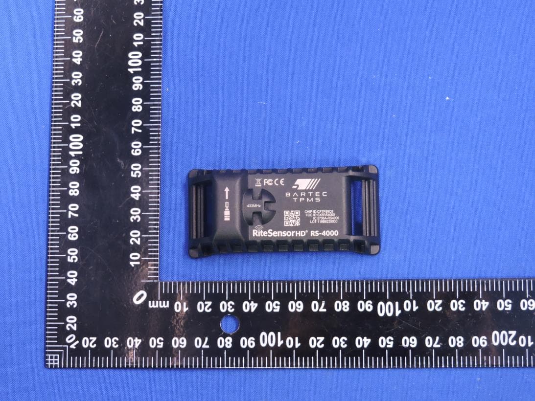
SX8RS4000
Mar 23, 2026Rite Sensor HD
Equipment Class
DSC - Part 15 Security/Remote Control Transmitter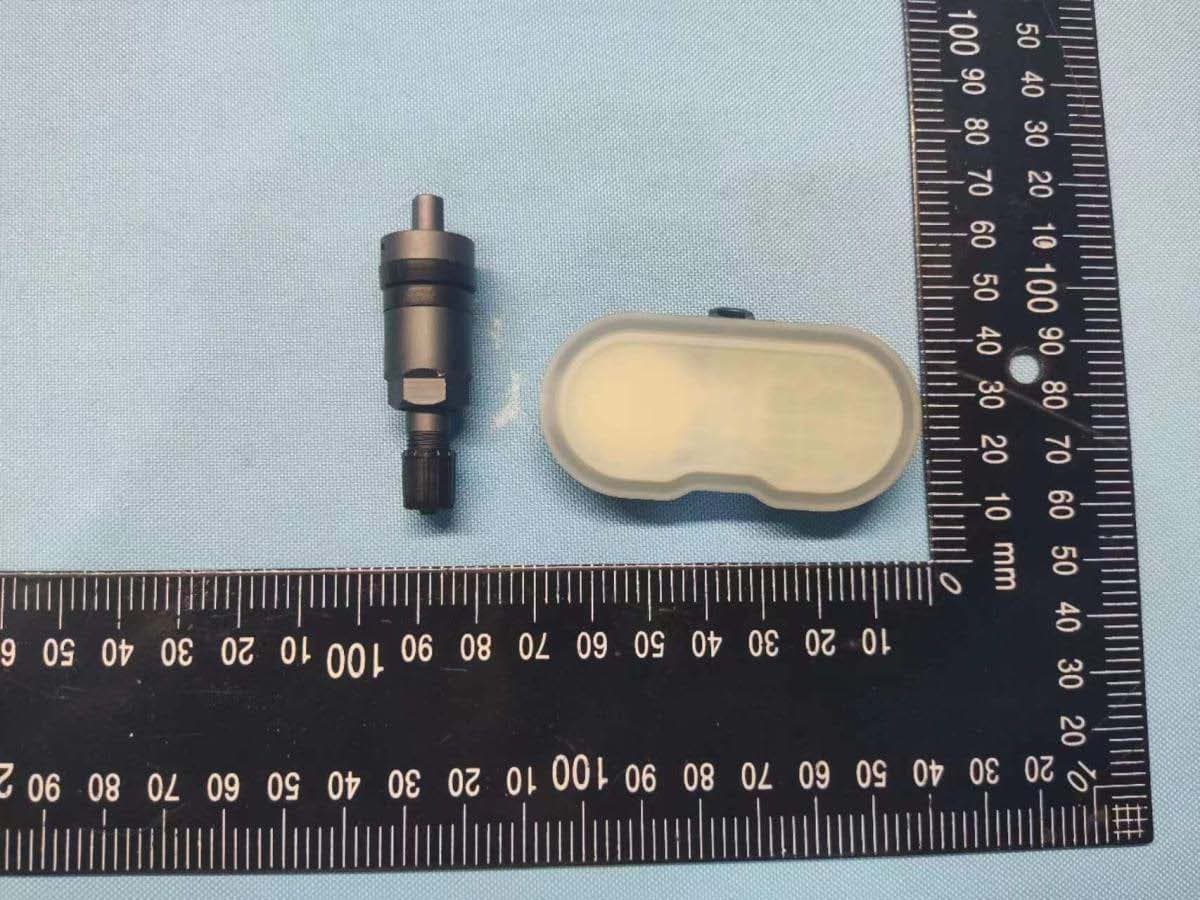
SX8-RS3000
Sep 21, 2022RITE-SENSOR BlueR
Equipment Class
DTS - Digital Transmission System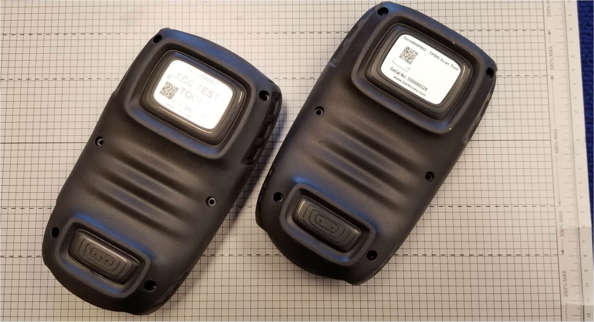
SX8DSW9
May 20, 2021LF TRANSMITTER
Equipment Class
DCD - Part 15 Low Power Transmitter Below 1705 kHz
SX8T500
Jul 08, 2013Tire Pressure Monitoring System Test Transmitter
Equipment Class
DCD - Part 15 Low Power Transmitter Below 1705 kHz
SX8TPMS-PAD
Oct 13, 2011Tire Pressure Programming Transmitter
Equipment Class
DCD - Part 15 Low Power Transmitter Below 1705 kHz