SX9RFID2RFID Device
DLP Design, Inc.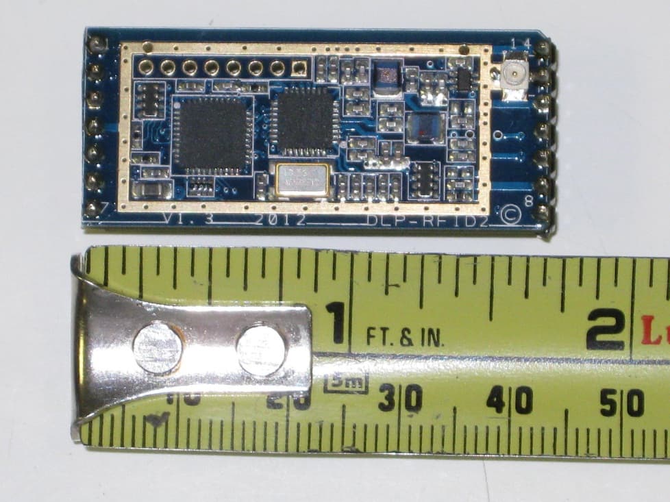
Click to zoom
Application Details
- Equipment Class
- DXX - Part 15 Low Power Communication Device Transmitter
- Date of Grant
- Jul 18, 2012
- Application Purpose
- Original Equipment
- Date of Application
- Jul 15, 2012
- Equipment Note
- RFID Device
- Frequency Range
- 13.56000000 - 13.56000000
- Company
- DLP Design, Inc.
- Country
- United States
Documents & Files
Document Text
Text extracted from the exhibit documents filed with the FCC. Open a document above to read the original.
Users Manual
www.dlpdesign.com [email protected] 2008 (Preliminary Data) DLP-RFID2 FEATURES: • ISO 15693, 18000-3, Tag-it™ HF-I Compatible • Read the UID/SID of Up To 15 Tags Simultaneously • 13.56MHz Reader/Writer • U.FL external antenna connector • On-board internal antenna • FCC/IC Modular Approvals Pending • Powered by 3.0 to 5.0 Volt Supply • TTL Serial Interface at 115200 baud • Operating Temperatures: 0°C to 70°C • Dimensions: (L x W x H) 1.65” x 0.735” x 0.17” APPLICATIONS: • Real-Time Security • Personal Identification • Pharmaceutical Tracking • Inventory/Asset Management & Tracking • Library/Book Management & Tracking • Baggage Tagging • Sports Event Timing 1.0 INTRODUCTION The DLP-RFID2 is a low-cost, compact module for reading from and writing to ISO 15693, ISO 18000-3, and Tag-it™ intelligent RFID transponder tags via an internal or an external antenna. It has the ability to both read and write up to 256 bytes of data in addition to reading the unique identifier (UID/SID). All of the DLP-RFID2’s electronics reside on a single compact PCB, and all operational power is taken from a single 3.0 to 5.0 volt supply. An external antenna can be connected via standard u.fl connector. 2.0 APPLICATION DEVELOPMENT Demonstration “C” source code is available (upon purchase) that demonstrates the communications protocol as developed for a microcontroller. www.dlpdesign.com [email protected] 2008 (Preliminary Data) 3.0 REGULATORY AGENCY CONSIDERATIONS 3.1 AGENCY IDENTIFICATION NUMBERS Compliance with the appropriate regulatory agencies is essential in the deployment of all transceiver devices. DLP Design is in the process of obtaining modular approval for this RF product such that an OEM need only meet a few basic requirements in order to utilize their end product under this approval. Corresponding agency identification numbers are listed below: Part Number US/FCC CAN/IC DLP-RFID2 SX9RFID2 5675A-RFID2 3.2 EXTERNAL ANTENNAS The DLP-RFID2 is approved for use with an external antenna. 3.3 FCC/IC REQUIREMENTS FOR MODULAR APPROVAL Any changes or modifications to the DLP-RFID2’s printed circuit board could void the user’s authority to operate the equipment. Operation of an unapproved antenna could void the user’s authority to operate the equipment. 3.4 WARNINGS Operation is subject to the following two conditions: (1) This device may not cause harmful interference, and (2) this device must accept any interference received, including interference that may cause undesirable operation. This device is intended for use under the following conditions: 1. The transmitter module may not be co-located with any other transmitter or antenna. 2. The module is approved using the FCC “unlicensed modular transmitter approval” method. As long as these two conditions are met, further transmitter testing will not be required. However, the OEM integrator is still responsible for testing their end product for any additional compliance measures necessitated by the installation of this module (i.e. digital device emissions, PC peripheral requirements, etc.). Note: In the event that these conditions cannot be met (i.e. co-location with another transmitter), then the FCC authorization is no longer valid and the corresponding FCC ID may not be used on the final product. Under these circumstances, the OEM integrator will be www.dlpdesign.com [email protected] 2008 (Preliminary Data) responsible for re-evaluating the end product (including the transmitter) and obtaining a separate FCC authorization. 3.5 OEM PRODUCT LABELING The final end product must be labeled in a visible area with the following text: “Contains TX FCC ID: SX9RFID2” 3.6 RF EXPOSURE In order to comply with FCC RF exposure compliance requirements, the antenna used for this transmitter must not be co-located or operating in conjunction with any other antenna or transmitter. 3.7 ADDITIONAL INFORMATION FOR OEM INTEGRATORS The end user should NOT be provided with any instructions on how to remove or install the DLP-RFID2. 4.0 DISCLAMER Neither the whole nor any part of the information contained herein nor the product described in this datasheet may be adapted or reproduced in any material or electronic form without the prior written consent of the copyright holder. This product and its documentation are supplied on an as-is basis, and no warranty as to their suitability for any particular purpose is either made or implied. DLP Design will not accept any claim for damages whatsoever arising as a result of use or failure of this product. Your statutory rights are not affected. This product or any variant of it is not intended for use in any medical appliance, device, or system in which the failure of the product might reasonably be expected to result in personal injury. This document provides preliminary information that may be subject to change without notice. www.dlpdesign.com [email protected] 2008 (Preliminary Data) 5.0 CONTACT INFORMATION DLP Design, Inc. 1605 Roma Lane Allen, TX 75013 Phone: 469-964-8027 Fax: 415-901-4859 Email: [email protected] Internet: http://www.dlpdesign.com
Cover Letter(s)
1605 Roma Lane • Allen, TX • 75013 Tel: 469-964-8027 • Fax: 415-901-4859 www.dlpdesign.com July 5, 2012 American Telecommunications Certification Body, Inc. 6731 Whittier Avenue, Suite C110 McLean, VA 22101 RE: AGENT’S AUTHORIZATION LETTER FCC ID: SX9RFID2 To Whom It May Concern: Professional Testing/ Jesse Banda is authorized to act on our behalf, until otherwise notified, for applications to American Certification Body, Inc. (ACB). We certify that we are not subject to denial of federal benefits, that includes FCC benefits, pursuant to Section 5301 of the Anti-Drug Abuse Act of 1988, 21 U.S.C. 862. Further, no party, as defined in 47 CFR 1.2002 (b), to the application is subject to denial of federal benefits, that includes FCC benefits. Thank you for your attention to this matter. Sincerely, Don L. Powrie President & CEO DLP Design, Inc.
Cover Letter(s)
Request for Confidentiality July 9, 2012 Subject: Confidentiality Request for FCC ID: SX9RFID2 Pursuant to FCC 47 CRF 0.457(d) and 0.459, the applicant requests that a part of the subject FCC application be held confidential. Type of Confidentiality Requested Exhibit Short Term xx Permanent Block Diagrams Short Term xx Permanent Operation Description/Theory of Operation Short Term xx Permanent Schematics _____DLP Design, Inc._____ has spent substantial effort in developing this product and it is one of the first of its kind in industry. Having the subject information easily available to "competition" would negate the advantage they have achieved by developing this product. Not protecting the details of the design will result in financial hardship. Permanent Confidentiality: The applicant requests the exhibits listed above as permanently confidential be permanently withheld from public review due to materials that contain trade secrets and proprietary information not customarily released to the public. Short-Term Confidentiality: The applicant requests the exhibits selected above as short term confidential be withheld from public view for a period of __N/A___ days from the date of the Grant of Equipment Authorization and prior to marketing. This is to avoid premature release of sensitive information prior to marketing or release of the product to the public. Applicant is also aware that they are responsible to notify ATCB in the event information regarding the product or the product is made available to the public. ATCB will then release the documents listed above for public disclosure pursuant to FCC Public Notice DA 04- 1705. Sincerely, By:___________________President/CEO ___Don Powrie___________ (Signature/Title 1 ) (Print name) 11/2008-1
Cover Letter(s)
1601 N. A. W. Grimes Blvd Suite B Round Rock, TX 78665 e-mail: [email protected] (512)244-3371 Fax: (512)244-1846 July 6, 2012 On behalf of DLP Design, Professional Testing (EMI), Inc. is seeking a modular approval for the RFID2 tag reading transmitter. Requirements listed in FCC part 15.212 are addressed below. 1) The device has a RF shield covering the RF generating portion of the circuit board. 2) The external data inputs are routed to a Texas Instruments MSP430F2370 microcontroller. All of the data inputs are buffered. 3) The module is powered from an external source of 3.0 to 5.0 Volts which is fed to the TRF7970A RFID IC which produces a locally regulated 3 Volt supply for the RF circuits and microcontroller. 4) The antenna requirement is satisfied by the use of an u.fl connector. 5) The module was tested connected to a battery powered test platform. 6) FCC ID is clearly printed in the PCB silk screen on the top side of the PCB. The manual contains the explicit directions to label the exterior of the device into which the RFID2 is integrated with “Contains FCC ID: SX9RFID2”. 7) The Users Manual explains that any modifications may strictly void the certification and a separate approval must be obtained. 8) Emissions are far below the RF Exposure limits, no exhibit attached.
External Photos
EUT with Demonstration board (top) EUT with Demonstration board (bottom) EUT with Antenna EUT with RF shield EUT without RF Shield Measurement of EUT without RF Shield (view 1) Measurement of EUT without RF Shield (view 2) Bottom of EUT
Internal Photos
EUT with Demonstration board (top) EUT with Demonstration board (bottom) EUT with Antenna EUT with RF shield EUT without RF Shield Measurement of EUT without RF Shield (view 1) Measurement of EUT without RF Shield (view 2) Bottom of EUT
Test Report
1601 North A.W. Grimes Blvd., Suite B Round Rock, TX78665 e-mail:[email protected] (512)244-3371 Fax:(512)244-1846 DLP Design 1605 Roma Lane Allen, TX 75013 Dear applicant: Enclosed is the Wireless Test Report for the DLP-RFID2 by DLP Design. This report can be used to demonstrate compliance with FCC and IC requirements for wireless devices in the United States and Canada. If you have any questions, please contact me. Sincerely, Jeffrey A. Lenk President Enclosure Professional Testing (EMI), Inc. DLP Design–DLP-RFID2 Wireless Test Report 13156-10 July 5, 2012 Page 2of 22 Project 13799-10 DLP Design DLP-RFID2 Wireless Test Report Prepared for: DLP Design 1605 Roma Lane Allen, TX 75013 Professional Testing (EMI), Inc. 1601 N. A.W. Grimes Blvd., Suite B Round Rock, Texas78665 July 6, 2012 Reviewed by Written by Jeffrey A. Lenk President Jesse Banda EMC Engineer Professional Testing (EMI), Inc. DLP Design–DLP-RFID2 Wireless Test Report 13156-10 July 5, 2012 Page 3of 22 Table of Contents Title Page .........................................................................................................................................1 1.0 Introduction ...........................................................................................................................5 1.1 Scope ................................................................................................................................5 1.2 EUT Description ..............................................................................................................5 1.3 Modifications ...................................................................................................................6 1.4 Test Site ...........................................................................................................................6 1.5 Applicable Documents .....................................................................................................6 1.6 Applicable Tests ...............................................................................................................6 2.0 Fundamental Field Strength Measurements..........................................................................7 2.1 Test Procedure .................................................................................................................7 2.2 Test Criteria .....................................................................................................................7 2.3 Test Equipment ................................................................................................................8 2.4 Test Results ......................................................................................................................8 3.0 Occupied Bandwidth ...........................................................................................................10 3.1 Test Procedure ...............................................................................................................10 3.2 Test Criteria ...................................................................................................................10 3.3 Test Equipment ..............................................................................................................10 3.4 Test Results ....................................................................................................................11 4.0 Out of Band Spurious Emissions ........................................................................................12 4.1 Test Procedure ...............................................................................................................12 4.2 Test Criteria ...................................................................................................................12 4.3 Test Equipment ..............................................................................................................13 4.4 Test Results ....................................................................................................................13 5.0 Antenna Requirements ........................................................................................................20 5.1 Evaluation Procedure .....................................................................................................21 5.2 Evaluation Criteria .........................................................................................................21 5.3 Evaluation Results .........................................................................................................21 End of Report .............................................................................................................................22 THIS REPORT SHALL NOT BE REPRODUCED EXCEPT IN FULL, WITHOUT THE WRITTEN APPROVAL OF PROFESSIONAL TESTING (EMI), INC. NOTICE:(1) This Report must not be used to claim product endorsement, by NVLAP, NIST, the FCC or any other Agency. This report also does not warrant certification by NVLAP or NIST. (2) This report shall not be reproduced except in full, without the written approval of Professional Testing (EMI), Inc. (3) The significance of this report is dependent on the representative character of the test sample submitted for evaluation and the results apply only in reference to the sample tested.The manufacturer must continuously implement the changes shown herein to attain and maintain the required degree of compliance. Professional Testing (EMI), Inc. DLP Design–DLP-RFID2 Wireless Test Report 13156-10 July 5, 2012 Page 4of 22 Applicant: DLP Design Applicant’s Address: 1605 Roma Lane Allen, TX 75013 FCC ID: SX9RFID2 IC ID: 5675A-RFID2 Project Number: 13799-10 Test Dates: July 5, 2012 The DLP Design RFID2 was tested to and found to be in compliance with FCC 47 CFR Part 15 and IC RSS-210 issue 8. The highest emissions generated by the above equipment are listed below: Parameter Frequency (MHz) Level Limit Margin (dB) OBW 99…
Text truncated - open the document above for the full version.
Test Setup Photos
Radiated Emission (rear view) Radiated Emission (front view) Close up of set up Temperature Tolerance set up Temperature Tolerance set up (door open) Close up of Temperature Tolerance set up Temperature Tolerance set up (voltage variation) Close up of Temperature Tolerance set up (voltage variation)
Contact Information
Applicant
Don Powrie(President/CEO)
Technical Contact
Professional TestingJesse Banda
[email protected]512-244-3371
1601 North A.W. Grimes Blvd. · Round Rock · United States
Test Firm
Professional Testing (EMI), Inc.Larry Finn
Technical Specifications
| # | Rule Parts | Frequency Range | Power Output |
|---|---|---|---|
| 1 | 15C | 13.56 MHz - 13.56 MHz | - |
Other Applications from DLP Design, Inc.
SX9RFS1
Feb 23, 2012Module
Equipment Class
DSS - Part 15 Spread Spectrum Transmitter
SX9UHF1B
Sep 04, 2009RFID Transmitter
Equipment Class
DSS - Part 15 Spread Spectrum Transmitter