SX9RFS1Module
DLP Design, Inc.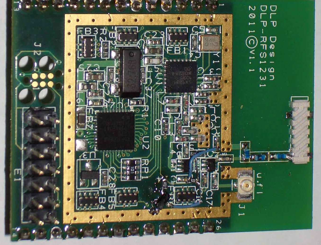
Click to zoom
Application Details
- Equipment Class
- DSS - Part 15 Spread Spectrum Transmitter
- Date of Grant
- Feb 23, 2012
- Application Purpose
- Original Equipment
- Date of Application
- Feb 23, 2012
- Equipment Note
- Module
- Frequency Range
- 902.00000000 - 928.00000000
- Company
- DLP Design, Inc.
- Country
- United States
Documents & Files
Document Text
Text extracted from the exhibit documents filed with the FCC. Open a document above to read the original.
Users Manual
Rev 1.1 (April 2009) 1 © DLP Design, Inc. D D L L P P - - R R F F S S 1 1 2 2 3 3 1 1 LEAD FREE 9 9 0 0 2 2 - - 9 9 2 2 8 8 M M H H z z D D a a t t a a R R a a d d i i o o **PRELIMINARY DOCUMENT-SUBJECT TO CHANGE** FEATURES: • 31 Channel FHSS • 17dBm Output Power • 1 Mile Range • U.FL Antenna Connector • On-Board Antenna • FCC/IC/CE Modular Approval In Place • Permanent, Unique Serial Number Built in • Single 3.3 Volt Supply APPLICATION AREAS: • Real-Time Security • Body-worn Medical Telemetry • Battery-Powered Home Automation • Electric/Water/Gas Automated Meter Reading • Industrial Monitoring And Control • Active RFID • Long Range Battery-Powered Multi-Hop Sensor Networks 1.0 INTRODUCTION The DLP-RFS1231 is a low-cost module for transmitting and receiving digital data via radio frequency. All of the DLP-RFS1231’s electronics (including an antenna) reside on a single PCB, and all operational power is derived from a single 3.3 volt supply. The transceiver design is made up of a Renesas RL78 low-power microcontroller (R5F100EEANA), a Semtech SX1231 low power, integrated UHF transceiver and an antenna switch for selecting between the on-board antenna and an optional external antenna. The hardware is designed for maximum range and optimum battery life. Rev 1.1 (April 2009) 2 © DLP Design, Inc. 2.0 SPECIFICATIONS Reader Frequency 902-928MHz Output Power 50mW (17dBm) MAX Range Up to 1 mile (Depends upon the antenna used) Protocol Frequency Hopping, Spread Spectrum Communications Interface TTL Serial Operational Power – Active TBDmA Operational Power – Idle TBDmA Antenna Connector u.fl* Operating Temperature 0-70°C *Please see the Antenna Section for important regulatory details. 3.0 SERIAL NUMBER Each DLP-RFS1231 contains a unique, 48-bit, hard-coded serial number that cannot be altered by any means. The serial number can be read via the microcontroller and used to identify the transceiver in the transmitted packets. 4.0 APPLICATION DEVELOPMENT A software library is available for free download upon purchase of the DLP-RFS1231 that demonstrates reading the serial number, transmitting and receiving data packets and setting up simple point-to-point and star networks. Rev 1.1 (April 2009) 3 © DLP Design, Inc. 5.0 REGULATORY AGENCY CONSIDERATIONS 5.1 AGENCY IDENTIFICATION NUMBERS Compliance with the appropriate regulatory agencies is essential in the deployment of all transceiver devices. DLP Design has obtained modular approval for this RF product. As such, an OEM need only meet a few basic requirements in order to utilize their end product under this approval. Corresponding agency identification numbers will be listed below: Part Number US / FCC CANADA / IC DLP-RFS1231 SX9RFS1 5675A-RFS1 5.2 EXTERNAL ANTENNAS The DLP-RFS1231 is pre-approved for use with both its on-board chip antenna and an external antenna part number 0600-00048 made by Laird Technologies. Connection to the external antenna is made via a u.fl connector. 5.3 FCC/IC REQUIREMENTS FOR MODULAR APPROVAL Any changes or modifications to the DLP-RFS1231’s printed circuit board, on-board antenna, or pre-approved external antenna could void the user’s authority to operate the equipment. 5.4 WARNINGS Operation is subject to the following two conditions: (1) This device may not cause harmful interference, and (2) this device must accept any interference received, including interference that may cause undesirable operation. This device is intended for use under the following conditions : 1. The transmitter module may not be co-located with any other transmitter or antenna; and, 2. The module will be approved using the FCC’s “unlicensed modular transmitter approval” method. As long as these two conditions are met, further transmitter testing will not be required. However, the OEM integrator is still responsible for testing their end product for any additional compliance measures necessitated by the installation of this module (i.e. digital device emissions, PC peripheral requirements, etc.). Note : In the event that these conditions cannot be met (i.e. co-location with another transmitter), then the FCC authorization is no longer valid, and the corresponding FCC ID may Rev 1.1 (April 2009) 4 © DLP Design, Inc. not be used on the final product. Under these circumstances, the OEM integrator will be responsible for re-evaluating the end product (including the transmitter) and obtaining a separate FCC authorization. 5.5 OEM PRODUCT LABELING The final end product must be labeled in a visible area with the following text: “Contains TX FCC ID: SX9RFS1” 5.6 RF EXPOSURE In order to comply with FCC RF exposure requirements, the antenna used for this transmitter must not be co-located or operating in conjunction with any other antenna or transmitter. 5.7 ADDITIONAL INFORMATION FOR OEM INTEGRATORS The end user should NOT be provided with any instructions on how to remove or install the DLP-RFS1231. This device will be pre-certified to operate with the antenna models listed below: • On-board Chip Antenna • Laird Technologies P/N 0600-00048 6.0 DISCLAMER Neither the whole nor any part of the information contained herein nor the product described in this datasheet may be adapted or reproduced in any material or electronic form without the prior written consent of the copyright holder. This product and its documentation are supplied on an as-is basis, and no warranty as to their suitability for any particular purpose is either made or implied. DLP Design will not accept any claim for damages whatsoever arising as a result of the use or failure of this product. Your statutory rights are not affected. This product or any variant of it is not intended for use in any medical appliance, device or system in which the failure of the product might reasonably be expected to result in personal injury. This document provides preliminary information that may be subject to change without notice. Rev 1.1 (April 2009) 5 © DLP Design, Inc. 7.0 CONTACT INFORMATION DLP Design…
Text truncated - open the document above for the full version.
Attestation Statements
Letter of Agency I appoint Intertek Testing Services NA Inc. to act on our behalf in front of the Federal Communications Commission with respect to all matters relating to certification of equipment under the FCC rules until further notice. I further certify that no party (as defined in 1.2002 of CFR 47, 1995) to this application, including myself, is subject to denial of federal benefits, that includes FCC benefits, pursuant to Section 5301 of the Anti-Drug Abuse Act of 1988, 21 U.S.C.,853A. Equipment: DLP-RFS1231 ________________________________________________________________________ ________________________________________________________________________ ________________________________________________________________________ Dated this 13th day of January, 2012 Signature ________Don Powrie___________________ Name ________CEO / President________________ Title ________DLP Design, Inc._______________ Company ________469-964-8027__________________ Telephone
Cover Letter(s)
Request for Confidentiality January 16, 2012 Subject: Confidentiality Request for FCC ID: SX9RFS1 Pursuant to FCC 47 CRF 0.457(d) and 0.459, the applicant requests that a part of the subject FCC application be held confidential. Type of Confidentiality Requested Exhibit Short Term xx Permanent Block Diagrams Short Term xx Permanent Operation Description/Theory of Operation Short Term xx Permanent Schematics _____DLP Design, Inc._____ has spent substantial effort in developing this product and it is one of the first of its kind in industry. Having the subject information easily available to "competition" would negate the advantage they have achieved by developing this product. Not protecting the details of the design will result in financial hardship. Permanent Confidentiality: The applicant requests the exhibits listed above as permanently confidential be permanently withheld from public review due to materials that contain trade secrets and proprietary information not customarily released to the public. Short-Term Confidentiality: The applicant requests the exhibits selected above as short term confidential be withheld from public view for a period of __N/A ___ days from the date of the Grant of Equipment Authorization and prior to marketing. This is to avoid premature release of sensitive information prior to marketing or release of the product to the public. Applicant is also aware that they are responsible to notify ATCB in the event information regarding the product or the product is made available to the public. ATCB will then release the documents listed above for public disclosure pursuant to FCC Public Notice DA 04- 1705. Sincerely, By:___________________President/CEO ___Don Powrie ___________ (Signature/Title 1 ) (Print name) 11/2008-1
Test Report
This report is for the exclusive use of Intertek's Client and is provided pursuant to the agreement between Intertek and its Client. Intertek's responsibility and liability are limited to the terms and conditions of the agreement. Intertek assumes no liability to any party, other than to the Client in accordance with the agreement, for any loss, expense or damage occasioned by the use of this report. Only the Client is authorized to permit copying or distribution of this report and then only in its entirety. Any use of the Intertek name or one of its marks for the sale or advertisement of the tested material, product or service must first be approved in writing by Intertek. The observations and test results in this report are relevant only to the sample tested. This report by itself does not imply that the material, product, or service is or has ever been under an Intertek certification program. EMC Report for DLP Design, Inc. on the RFS1231 FCCID: SX9RFS1; ICID: 5675A-RFS1 Page 1 of 39 1809 10 th St. # 400 Plano TX 75074 Telephone: 972-202-8800 Facsimile: 972-202-8801 www.intertek-etlsemko.com TEST REPORT Report Number: 100603150DAL-001 Project Number: G100603150 Report Issue Date: January 24th, 2012 Product Name: RFS1231 Frequency Hopping Data Radio FCCID: SX9RFS1 ICID: 5675A-RFS1 Standards: FCC 47CFR 15C*BEI Issued:2007/10/01 Title 47 CFR Part 15 Subpart C: Intentional Radiators. RSS 210*BEI Issued:2007/06/01 Issue:7 Low Power License-Exempt Radiocommunication Devices (All Frequency Bands): Category I Equipment Tested by: Client: Intertek Testing Services NA, Inc. 1809 10 th ST #400 Plano, TX 75074 - USA DLP Design, Inc. 1605 Roma Lane Allen, TX 75013 - USA Report prepared by Report reviewed by Shawn K McGuinness EMC Engineer Jeremy O. Pickens Senior Staff Engineer Intertek Report Number: 100603150DAL-001 Issued: 01/24/2012 EMC Report for DLP design, Inc. on the RFS1231 FCCID: SX9RFS1; ICID: 5675A-RFS1 Page 2 of 39 TABLE OF CONTENTS 1 Introduction and Conclusion .............................................................................................................. 3 2 Test Summary ...................................................................................................................................... 3 3 Peak Conducted Power ....................................................................................................................... 6 Project # ....................................................................................................................................................... 7 Date............................................................................................................................................................... 7 Rule............................................................................................................................................................... 7 Distance ....................................................................................................................................................... 7 Antenna ........................................................................................................................................................ 7 RBW.............................................................................................................................................................. 7 VBW .............................................................................................................................................................. 7 Detector........................................................................................................................................................ 7 4 Occupied Bandwidth ........................................................................................................................... 8 5 Conducted Spurious Emissions and Band Edge Spurious Emissions........................................ 18 6 Timing, Channel Separation and Number of Hopping Channels .................................................. 24 7 Radiated Spurious Emissions (Transmitter) ................................................................................... 28 8 Radiated Spurious Emissions (Receiver)........................................................................................ 37 9 AC Power Line Conducted Emissions............................................................................................. 37 10 Antenna Requirement per FCC Part 15.203 ................................................................................. 37 11 Measurement Uncertainty.............................................................................................................. 38 12 Revision History ............................................................................................................................. 39 Intertek Report Number: 100603150DAL-001 Issued: 01/24/2012 EMC Report for DLP design, Inc. on the RFS1231 FCCID: SX9RFS1; ICID: 5675A-RFS1 Page 3 of 39 1 Introduction and Conclusion The tests indicated in section 2 were performed on the product constructed as described in section 3. The remaining test sections are the verbatim text from the actual data sheets used during the investigation. These test sections include the test name, the specified test method, a list of the actual test equipment used, documentation photos, results and raw data. No additions, deviations, or exclusions have been made from the standard(s) unless specifically noted. Based on the results of our investigation, we have concluded the product tested complied with the requirements of the standard(s) indicated. The results obtained in this test report pertain only to the item(s) tested. The INTERTEK-Dallas is located at 1809 10 th St. # 400, Plano TX 75074. The radiated emission test site is a 3-meter semi-anechoic chamber. The chamber meets the characteristics of CISPR 16-1 and ANSI C63.4. For measurements,…
Text truncated - open the document above for the full version.
Contact Information
Applicant
Don Powrie(President/CEO)
Test Firm
Intertek Testing Services NA, Inc.Paul Coghill
Technical Specifications
| # | Rule Parts | Frequency Range | Power Output |
|---|---|---|---|
| 1 | 15C | 902 MHz - 928 MHz | 50.00 mW |
Other Applications from DLP Design, Inc.
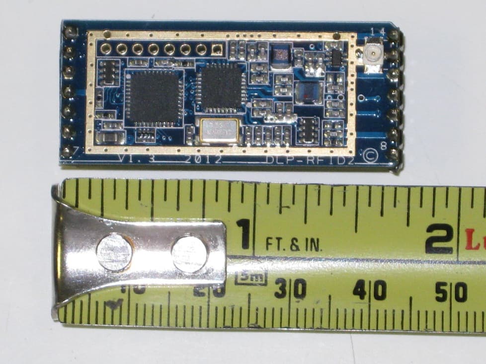
SX9RFID2
Jul 18, 2012RFID Device
Equipment Class
DXX - Part 15 Low Power Communication Device Transmitter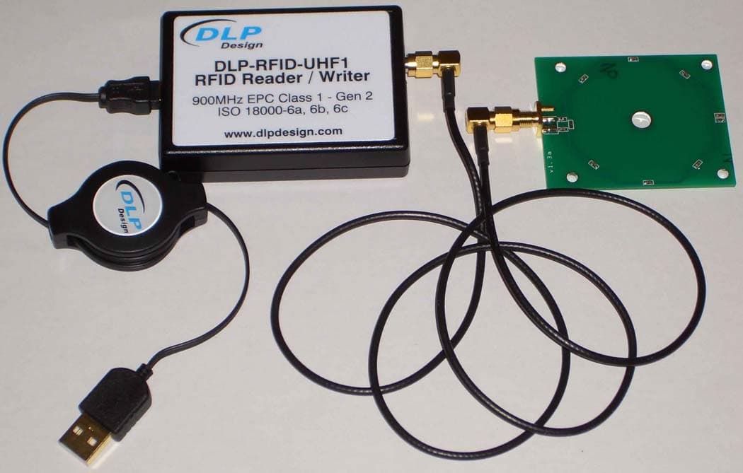
SX9UHF1B
Sep 04, 2009RFID Transmitter
Equipment Class
DSS - Part 15 Spread Spectrum Transmitter