SXNLSNM-0002-XLight Sensory Network Module
Sensity Systems
Click to zoom
Application Details
- Equipment Class
- NII - Unlicensed National Information Infrastructure TX
- Date of Grant
- Aug 07, 2014
- Application Purpose
- Original Equipment
- Date of Application
- Aug 07, 2014
- Equipment Note
- Light Sensory Network Module
- Frequency Range
- 5660.00000000 - 5700.00000000
- Company
- Sensity Systems
- Country
- United States
Documents & Files
Document Text
Text extracted from the exhibit documents filed with the FCC. Open a document above to read the original.
Cover Letter(s)
Sensity Systems Inc. | 480 Oakmead Parkway | Sunnyvale, CA 94085 | (408) 841-4200 | www.sensity.com July 1, 14 FEDERAL COMMUNICATIONS COMMISSIONS Authorization and Evaluation Division 7435 Oakland Mills Road Columbia, MD 21046 Subject: Confidentiality Request regarding application for certification of FCC ID: SXNLSNM-0002-X. In accordance with Sections 0.457 and 0.459 of the Commission’s Rules, Sensity Systems hereby requests long-term confidential treatment of information accompanying this application as outlined below: Block Diagram Schematics Operation Description The above materials contain proprietary and confidential information not customarily released to the public. The public disclosure of these materials provides unjustified benefits to its competitors in the market. Sincerely, Christopher Hizer Christopher Hizer HW Engineer Sensity Systems 480 Oakmead Parkway Sunnyvale, CA 94085
Cover Letter(s)
Sensity Systems Inc. | 480 Oakmead Parkway | Sunnyvale, CA 94085 | (408) 841-4200 | www.sensity.com July 1, 14 FEDRAL COMMUNICATIONS COMMISIONS Authorizations and Evaluation Division 7435 Oakland Mills Road Columbia, MD 21046 Subject: Modular Approval Requirements Statement in Accordance to DA 00‐1407 To whom it may concern: We, Sensity Systems, the undersigned, hereby request a grant of modular approval for this device as the design is intended to be used in conjunction with our commercially available lighting products. This device is designed to allow for end user control, provide measurement and monitoring of the clients lighting network. We, Sensity Systems, also state the following statements of conformity to the application of Modular Approval for product LSNM‐0002‐X, under Grantee Code SXN. 1) The modular transmitter used in product LSNM‐0002‐X has an integrated wireless module chip provided by manufacturer Taiyo Yuden with manufacturing part # WYSBMVGX4. This part has been verified by both manufacturer (Taiyo Yuden) and integrator (Sensity Systems) to have its own RF shielding with no additional coupling. 2) This modular transmitter does not have buffered modulation/ data inputs as it does not apply to this application/ design. 3) The module has two dedicated power supplies, regulating power to the transmitter. Power regulation is performed via a 3.3 ‐ 1.8vDC (U21) and a 5 ‐ 3.3vDC (U22) converter. 4) Under modular approval guidelines, we claim to meet the outlined requirements as having a ‘unique connector’ due to the following conditions: a. Transmitter module antenna utilizes a QMA connector b. External antenna cable utilizes an QMA to RP‐N Type connector c. External antenna utilizes and RP‐N Type connector 5) Transmitter module is not dependent to the enclosure housing and does not rely on such for additional shielding or power. The module is designed to be powered 2 independent of the packaging enclosure and will meet the AC line testing requirements per Section 15.207. 6) Upon Modular Approval application acceptance, the transmitter module will contain the following to comply with the labeling requirements. Refer to document FCC_Label_Example document for proposed label formats. a. PCB containing the transmitter will be labeled with the appropriate FCC logo and FCC ID. b. Module packaging enclosure will contain a label stating “Contains FCC ID: ABCXYZModel1”; along with company identification information. 7) No special operating requirements are required for product LSNM‐0002‐X. 8) Upon completion of testing, data will verify product operates within the specified RF exposure levels. This application is not designed to be used as a Mobile Communication or Personal Communication Device; thus complying to sections 2.1091, 2.1093 is not required or tested against. However, this application is designed and tested in accordance to FCC Part 15 Sections 15.3.19(i), 15.407(f), 152.53(f), 15.255(g) exposure requirements. Regards, Christopher Hizer Christopher Hizer HW Engineer Sensity Systems 480 Oakmead Parkway Sunnyvale, CA 94085
External Photos
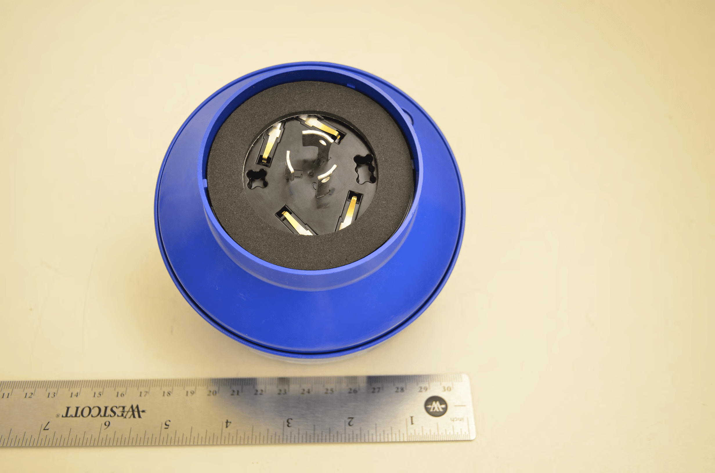
Sensity Systems, Inc. FCC ID: SXNLSNM-0002-X Report Number: R1404241-407 Page 109 of 113 FCC Part 15.407 Test Report 16 Exhibit C – EUT Photographs 16.1 Module with Enclosure and the External Antenna View 16.2 EUT - Top View Sensity Systems, Inc. FCC ID: SXNLSNM-0002-X Report Number: R1404241-407 Page 110 of 113 FCC Part 15.407 Test Report 16.3 EUT - Bottom View 16.4 EUT - Side View Sensity Systems, Inc. FCC ID: SXNLSNM-0002-X Report Number: R1404241-407 Page 111 of 113 FCC Part 15.407 Test Report 16.5 Antenna 1 View (5 GHz) 16.6 Antenna 2 View (2.4 GHz)
ID Label/Location Info
930-0046-00, Rev 02 Company Confidential 1 Marking Requirements LSNM-0002-X (Light Sensory Network Module – CoreNode) DOCUMENT NUMBER: 930-0046-00 OWNER: Operations ORIGINATOR: Christopher Hizer STATUS: Released LOCATION: Agile CHANGE HISTORY REVISION DATE HANDLED BY COMMENTS 01 07/11/14 Christopher Hizer Initial Release: ECO-00560 02 07/24/14 Christopher Hizer Include Sensor Pod Label: ECO-00574 930-0046-00, Rev 02 Company Confidential 2 Table of Contents 1.0 NETWORK IDENTIFIER 2.0 SENSOR POD 3.0 PRODUCT LABEL 4.0 PLACEMENT LOCATIONS 930-0046-00, Rev 02 Company Confidential 3 1.0 NETWORK IDENTIFIER Font Font (Size) Font Type Requirement Actual 16.5 x 8mm -- Sensity Logo Sensity Logo 8 Arial Bold Node ID (NID) Variable: Generated During Test 8 Arial Bold MAC Address (MAC) Variable: Generated During Test 5 x 5 mm Data Matrix Code NID and MAC Network Identifier Example 2" 1 / 2 " MAC:00:10:B5:C4:99:6A NID: N0198C24C 2.0 Sensor ID Font Font (Size) Font Type Requirement Actual 16.5 x 8mm -- Sensity Logo Sensity Logo 8 Arial Bold Sensor ID Variable: Generated During Test 5 x 5 mm Data Matrix Code Sensor ID Sensor ID Example 2.00 0 . 50 S1234567890123 930-0046-00, Rev 02 Company Confidential 4 3.0 PRODUCT LABEL Font Font Size Font Type Requirement Actual 9 x 20mm Company Name Sensity Logo 10 Arial Bold Model LSNM-0002-X(Variable: A=2dbi / B=8dbi) 10 Arial Bold Serial Number Variable 10 Arial Bold Environmental Suitability SUITABLE FOR DAMP LOCATION 8 Arial Bold Input Electrical Rating 120-277V / 2mA / 50-60Hz 8 Arial Bold Output Electrical Rating 120-277V / 10A / 50-60Hz 6 Arial Bold FCC ID FCC ID: SXNLSNM-0002-X 8 x 8mm Data Matrix Model, Serial Number 10 x 10mm Safety Mark cCSAus Logo Serial Number Convention PPP DDDD F SSSSSSSS P = Product Family Product Family Manufacturing ID D = DOM as WWYY 010 LSNM A Sunnyvale (HQ) F = Manufacturing Location S = Serial Number (8-digits) Product Label Example 3.00 2 . 00 SUITABLE FOR DAMP LOCATION LSNM-0002-X FCC ID: SXNLSNM-0002-X Input Rating (NO LOAD):120-277V / 2mA / 50-60HZ PPPWWYYF00000001 Output Rating (LOAD): 120-277V / 10A / 50-60HZ 930-0046-00, Rev 02 Company Confidential 5 4.0 PLACEMENT LOCATION Micronode Board Level Network Identifier 2" 1 / 2 " MAC:00:10:B5:C4:99:6A NID: N0198C24C Enclosure Level 3" 2 " SUITABLE FOR DAMP LOCATION LSNM-0002-X 010WWYYFSSSSSSSS Input Rating (No Load): 120-277V / 2mA / 50-60HZ MAC:00:10:B5:C4:99:6A NID: N0198C24C Second Network Identifier Label FCC ID: SXNLSNM-0002-X 120-277V / 10A / 50-60HZ Output Rating (Load): 930-0046-00, Rev 02 Company Confidential 6 Sensor Pod 2.00 0 . 50 S1234567890123 Product Level 3" 2 " SUITABLE FOR WET LOCATIONS XLE-5MS-118-50P7-UAC-G4 AC INPUT:120-277V / 40W / 50-60HZ 010WWYYFSSSSSSSS S10-000011 Contains FCC ID: SXNLSNM-0002-X Third Network Identifier Label MAC:00:10:B5:C4:99:6A NID: N0198C24C 930-0046-00, Rev 02 Company Confidential 7
Internal Photos
Sensity Systems, Inc. FCC ID: SXNLSNM-0002-X Report Number: R1404241-407 Page 112 of 113 FCC Part 15.407 Test Report 16.7 EUT – Open Case View 16.8 Sensor Board Component Top View Sensity Systems, Inc. FCC ID: SXNLSNM-0002-X Report Number: R1404241-407 Page 113 of 113 FCC Part 15.407 Test Report 16.9 Sensor Board Component Bottom View --- END OF REPORT ---
RF Exposure Info
Sensity Systems, Inc. FCC ID: SXNLSNM-0002-X Report Number: R1404241-407 Page 11 of 113 FCC Part 15.407 Test Report 4 FCC §15.407(f) & §2.1091 - RF Exposure 4.1 Applicable Standard According to FCC §15.407(f) and §1.1307(b)(1), systems operating under the provisions of this section shall be operated in a manner that ensures that the public is not exposed to radio frequency energy level in excess of the Commission’s guidelines. Limits for General Population/Uncontrolled Exposure Frequency Range (MHz) Electric Field Strength (V/m) Magnetic Field Strength (A/m) Power Density (mW/cm 2 ) Averaging Time (minutes) Limits for General Population/Uncontrolled Exposure 0.3-1.34 614 1.63 * (100) 30 1.34-30 824/f 2.19/f * (180/f 2 ) 30 30-300 27.5 0.073 0.2 30 300-1500 / / f/1500 30 1500-100,000 / / 1.0 30 f = frequency in MHz * = Plane-wave equivalent power density 4.2 MPE Prediction Predication of MPE limit at a given distance, Equation from OET Bulletin 65, Edition 97-01 S = PG/4R² Where: S = power density P = power input to antenna G = power gain of the antenna in the direction of interest relative to an isotropic radiator R = distance to the center of radiation of the antenna 4.3 MPE Results W52 Band: Maximum peak output power at antenna input terminal (dBm): 13.36 Maximum peak output power at antenna input terminal (mW): 21.67 Prediction distance (cm): 20 Prediction frequency (MHz): 5240 Maximum Antenna Gain, typical (dBi): 8.0 Maximum Antenna Gain (numeric): 6.309 Power density of prediction frequency at 20.0 cm (mW/cm 2 ): 0.027 MPE limit for uncontrolled exposure at prediction frequency (mW/cm 2 ): 1.0 Sensity Systems, Inc. FCC ID: SXNLSNM-0002-X Report Number: R1404241-407 Page 12 of 113 FCC Part 15.407 Test Report W53 Band: Maximum peak output power at antenna input terminal (dBm): 14.57 Maximum peak output power at antenna input terminal (mW): 28.64 Prediction distance (cm): 20 Prediction frequency (MHz): 5320 Maximum Antenna Gain, typical (dBi): 8.0 Maximum Antenna Gain (numeric): 6.309 Power density of prediction frequency at 20.0 cm (mW/cm 2 ): 0.035 MPE limit for uncontrolled exposure at prediction frequency (mW/cm 2 ): 1.0 W56 Band: Maximum peak output power at antenna input terminal (dBm): 13.10 Maximum peak output power at antenna input terminal (mW): 20.41 Prediction distance (cm): 20 Prediction frequency (MHz): 5700 Maximum Antenna Gain, typical (dBi): 8.0 Maximum Antenna Gain (numeric): 6.309 Power density of prediction frequency at 20.0 cm (mW/cm 2 ): 0.025 MPE limit for uncontrolled exposure at prediction frequency (mW/cm 2 ): 1.0 The device meets FCC MPE requirement for uncontrolled exposure environment at 20 cm distance.
Test Report
Note : This test report is prepared for the customer shown above and for the device described herein. It may not be duplicated or used in part without prior written consent from Bay Area Compliance Laboratories Corp. This report must not be used by the customer to claim product certification, approval, or endorsement by A2LA* or any agency of the Federal Government. * This report may contain data that are not covered by the A2LA accreditation and are marked with an asterisk “*” (Rev.3) FCC PART 15.407 TEST AND MEASUREMENT REPORT For Sensity Systems, Inc. 480 Oakmead Parkway, Sunnyvale, CA 94085, USA Report Type: Original Report Product Type: Light Sensory Module Prepared By: Chen Ge Test En gineer Report Number: R1404241-407 Report Date: 2014-07-11 Reviewed By: Ivan Cao RF Lead Bay Area Compliance Laboratories Corp. 1274 Anvilwood Avenue, Sunnyvale, CA 94089, USA Tel: (408) 732-9162 Fax: (408) 732-9164 FCC ID: SXNLSNM-0002-X Sensity Systems, Inc. FCC ID: SXNLSNM-0002-X Report Number: R1404241-407 Page 2 of 113 FCC Part 15.407 Test Report TABLE OF CONTENTS 1 GENERAL DESCRIPTION ......................................................................................................................................... 6 1.1 PRODUCT DESCRIPTION FOR EQUIPMENT UNDER TEST (EUT) ................................................................................. 6 1.2 MECHANICAL DESCRIPTION OF EUT ....................................................................................................................... 6 1.3 OBJECTIVE ............................................................................................................................................................... 6 1.4 RELATED SUBMITTAL(S)/GRANT(S) ........................................................................................................................ 6 1.5 TEST METHODOLOGY .............................................................................................................................................. 6 1.6 MEASUREMENT UNCERTAINTY ............................................................................................................................... 6 1.7 TEST FACILITY ........................................................................................................................................................ 7 2 EUT TEST CONFIGURATION .................................................................................................................................. 9 2.1 JUSTIFICATION ......................................................................................................................................................... 9 2.2 EUT EXERCISE SOFTWARE ...................................................................................................................................... 9 2.3 EQUIPMENT MODIFICATIONS ................................................................................................................................... 9 2.4 SPECIAL ACCESSORIES ............................................................................................................................................ 9 2.5 LOCAL SUPPORT EQUIPMENT .................................................................................................................................. 9 2.6 EUT INTERNAL CONFIGURATION DETAILS .............................................................................................................. 9 2.7 INTERFACE PORTS AND CABLES .............................................................................................................................. 9 3 SUMMARY OF TEST RESULTS ............................................................................................................................. 10 4 FCC §15.407(F) & §2.1091 - RF EXPOSURE .......................................................................................................... 11 4.1 APPLICABLE STANDARD ........................................................................................................................................ 11 4.2 MPE PREDICTION .................................................................................................................................................. 11 4.3 MPE RESULTS ....................................................................................................................................................... 11 5 FCC §15.203 – ANTENNA REQUIREMENTS ........................................................................................................ 13 5.1 APPLICABLE STANDARD ........................................................................................................................................ 13 5.2 ANTENNA LIST ...................................................................................................................................................... 13 6 FCC §15.207 - AC POWER LINE CONDUCTED EMISSIONS ............................................................................ 14 6.1 APPLICABLE STANDARDS ...................................................................................................................................... 14 6.2 TEST SETUP ........................................................................................................................................................... 14 6.3 TEST PROCEDURE .................................................................................................................................................. 14 6.4 TEST SETUP BLOCK DIAGRAM ............................................................................................................................... 15 6.5 CORRECTED AMPLITUDE & MARGIN CALCULATION ............................................................................................. 15 6.6 TEST EQUIPMENT LIST AND DETAILS ................................................................................…
Text truncated - open the document above for the full version.
Test Report
Note: This test report is prepared for the customer shown above and for the device described herein. It may not be duplicated or used in part without prior written consent from Bay Area Compliance Laboratories Corp. This report must not be used by the customer to claim product certification, approval, or endorsement by A2LA* or any agency of the Federal Government. * This report may contain data that are not covered by the A2LA accreditation and are marked with an asterisk “*” (Rev.3) FCC PART 15.407(H) DYNAMIC FREQUENCY SELECTION TEST AND MEASUREMENT REPORT For Sensity Systems, Inc. 480 Oakmead Parkway, Sunnyvale, CA 94085, USA Report Type: Original Report Product Type: Light Sensory Module Prepared By: Chen Ge Test En gineer Report Number: R1404241-FCC DFS Report Date: 2014-07-11 Reviewed By: Ivan Cao RF Lead Bay Area Compliance Laboratories Corp. 1274 Anvilwood Avenue, Sunnyvale, CA 94089, USA Tel: (408) 732-9162 Fax: (408) 732-9164 FCC ID: SXNLSNM-0002-X Sensity Systems, Inc. FCC ID: SXNLSNM-0002-X Report Number: R1404241-FCC DFS Page 2 of 44 FCC 15.407(H) DFS Test Report TABLE OF CONTENTS 1 GENERAL DESCRIPTION ................................................................................................................................ 4 1.1 PRODUCT DESCRIPTION FOR EQUIPMENT UNDER TEST (EUT) ........................................................................ 4 1.2 MECHANICAL DESCRIPTION OF EUT .............................................................................................................. 4 1.3 OBJECTIVE ...................................................................................................................................................... 4 1.4 RELATED SUBMITTAL(S)/GRANT(S) ............................................................................................................... 4 1.5 TEST METHODOLOGY ..................................................................................................................................... 4 1.6 TEST FACILITY ............................................................................................................................................... 5 2 EUT TESTY CONFIGURATION ...................................................................................................................... 7 2.1 JUSTIFICATION ................................................................................................................................................ 7 2.2 EUT EXERCISE SOFTWARE ............................................................................................................................. 7 2.3 EUT INTERNAL CONFIGURATION DETAILS ..................................................................................................... 7 2.4 EXTERNAL I/O CABLING LIST AND AC CORD ................................................................................................ 7 2.5 LOCAL SUPPORT EQUIPMENT ......................................................................................................................... 7 3 SUMMARY OF TEST RESULTS ...................................................................................................................... 8 4 APPLICABLE STANDARDS ............................................................................................................................. 9 4.1 DFS REQUIREMENTS ...................................................................................................................................... 9 4.2 DFS MEASUREMENT SYSTEM ...................................................................................................................... 11 4.3 SYSTEM BLOCK DIAGRAM ............................................................................................................................ 12 4.4 CONDUCTED METHOD .................................................................................................................................. 12 4.5 RADIATED METHOD ..................................................................................................................................... 14 4.6 TEST PROCEDURE ......................................................................................................................................... 14 5 TEST RESULTS ................................................................................................................................................. 15 5.1 DESCRIPTION OF EUT ................................................................................................................................... 15 5.2 TEST EQUIPMENT LIST AND DETAILS ........................................................................................................... 15 5.3 RADAR WAVEFORM CALIBRATION ............................................................................................................... 16 5.4 TEST ENVIRONMENTAL CONDITIONS ............................................................................................................ 16 6 CHANNEL MOVE TIME & CHANNEL CLOSING TRANSMISSION TIME .......................................... 23 6.1 TEST PROCEDURE ......................................................................................................................................... 23 6.2 TEST RESULTS .............................................................................................................................................. 23 7 NON-OCCUPANCY PERIOD .......................................................................................................................... 36 7.1 TEST PROCEDURE ......................................................................................................................................... 36 7.2 TEST RESULTS .............................................................................................................................................. 36 8 EXHIBIT A – TEST SETUP PHOTOGRA…
Text truncated - open the document above for the full version.
Test Setup Photos
Sensity Systems, Inc. FCC ID: SXNLSNM-0002-X Report Number: R1404241-407 Page 106 of 113 FCC Part 15.407 Test Report 15 Exhibit B - EUT Setup Photographs 15.1 Conducted Emissions - Front View 15.2 Conducted Emissions - Side View Sensity Systems, Inc. FCC ID: SXNLSNM-0002-X Report Number: R1404241-407 Page 107 of 113 FCC Part 15.407 Test Report 15.3 Radiated Emission Front View 15.4 Radiated Emission below 1 GHz Rear View Sensity Systems, Inc. FCC ID: SXNLSNM-0002-X Report Number: R1404241-407 Page 108 of 113 FCC Part 15.407 Test Report 15.5 Radiated Emission above 1 GHz Rear View 15.6 Radiated Emission above 1 GHz Front View
Contact Information
Applicant
Christoher Hizer Hizer(HW Engineer)
Test Firm
Bay Area Compliance Laboratories Corp.Lisa Tang
Technical Specifications
| # | Rule Parts | Frequency Range | Power Output |
|---|---|---|---|
| 4 | 15E | 5.66 GHz - 5.70 GHz | 20.40 mW |
Other Applications from Sensity Systems
SXNWYSBMVGX41
Nov 09, 2015CORE NODE EXTERNAL, WIFI
Equipment Class
NII - Unlicensed National Information Infrastructure TX
SXNLSNM-0001-A
Dec 21, 2013Light Sensory Network Module
Equipment Class
DTS - Digital Transmission System