SY4-B01004Handheld GNSS Data Collector
Shanghai Huace Navigation Technology Ltd.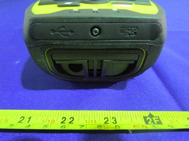
Click to zoom
Application Details
- Equipment Class
- PCB - PCS Licensed Transmitter
- Date of Grant
- Feb 08, 2015
- Application Purpose
- Original Equipment
- Date of Application
- Jan 30, 2015
- Equipment Note
- Handheld GNSS Data Collector
- Frequency Range
- 1852.40000000 - 1907.60000000
- Country
- China
Documents & Files
Document Text
Text extracted from the exhibit documents filed with the FCC. Open a document above to read the original.
Users Manual
il LT500 | GETTING STARTED GUIDE GNSS/GIS HANDHELD RECEIVER Copyright Copyright 2014 CHC Shanghai HuaCe Navigation Technology Ltd. All rights reserved. The CHC is trademark of Shanghai Huace Navigation Technology Limited. All other trademarks are the property of their respective owners. Trademarks All product and brand names mentioned in this publication are trademarks of their respective holders. Safety Warnings The Global Positioning System (GPS) is operated by the U.S. Government, which is solely responsible for the accuracy and maintenance of the GPS network. Accuracy can also be affected by poor satellite geometry and obstructions, like buildings and heavy canopy. FCC interference statement This equipment has been designed to comply with the limits for a class B digital device, pursuant to part 15 of the FCC Rules in the Portable Mode. These limits are designed to provide reasonable protection against harmful interference in a residential installation. Operation is subject to the following two conditions: (1) this device may not cause harmful interference and (2) this device must accept any interference received, including interference that may cause undesired operation. LT500 Getting Started Guide – Revision 1.0 Sep 2014 Changes or modifications made to this equipment not expressly approved by Shanghai Huace Navigation Technology Ltd. may void the FCC authorization to operate this equipment. NOTE: This equipment has been tested and found to comply with the limits for a Class B digital device, pursuant to Part 15 of the FCC Rules. These limits are designed to provide reasonable protection against harmful interference in a residential installation. This equipment generates, uses and can radiate radio frequency energy and, if not installed and used in accordance with the instructions, may cause harmful interference to radio communications. However, there is no guarantee that interference will not occur in a particular installation. If this equipment does cause harmful interference to radio or television reception, which can be determined by turning the equipment off and on, the user is encouraged to try to correct the interference by one or more of the following measures: Reorient or relocate the receiving antenna. Increase the separation between the equipment and receiver. Connect the equipment into an outlet on a circuit different from that to which the receiver is connected. Consult the dealer or an experienced radio/TV technician for help. The SAR limit adopted by USA (FCC) is 1.6 Watts/kilogram (W/kg) averaged over one gram of tissue. Device types (FCC ID: SY4-B01004) has also been tested against this SAR limit. The highest SAR value reported under this standard during product certification for 2G/3G mode is 0.227 W/kg. The highest SAR value reported under this standard during product certification for 2.4GHz WLAN mode is 0.956 W/kg. The highest SAR value reported under this standard during product certification for simultaneous mode is 1.183 W/kg. This device was tested for typical body-worn operations with the back of the handset kept 0 cm from the body. To maintain compliance with FCC RF exposure requirements, use accessories that maintain a 0 cm separation distance between the user’s body and the back of handset. The use of belt clips, holsters and similar accessories should not contain metallic components in its assembly. The use of accessories that do not satisfy these requirements may not comply with FCC RF exposure requirements, and should be avoided. Table of Contents 1. Introduction ..................................................................................................................................... 1 1.1. Technical Assistance ........................................................................................................... 1 1.2. Your Comments .................................................................................................................. 1 2. Overview .......................................................................................................................................... 2 2.1. Features .............................................................................................................................. 2 2.2. Specifications ..................................................................................................................... 2 3. Description ....................................................................................................................................... 4 4. First-Time Use .................................................................................................................................. 6 4.1. Inserting the Battery, Storage card and SIM card .............................................................. 6 4.2. Charging the Battery .......................................................................................................... 6 4.3. Turning the device on/off or standby ................................................................................ 7 4.4. Connect to Office Computer .............................................................................................. 7 4.5. Installing Software .............................................................................................................. 8 4.6. Using GNSS Positioning ...................................................................................................... 8 4.7. Using GNSSViewer .............................................................................................................. 8 4.8. Using the camera ............................................................................................................. 10 4.9. Establishing Wireless connection (Bluetooth /Wi-Fi) ....................................................... 10 5. Getting started with SurvCE 3 ................................................................................…
Text truncated - open the document above for the full version.
Block Diagram
WIFI/BT GSM/UMTS GPS
Cover Letter(s)
QA-FR-170-B Shanghai Huace Navigation Technology LTD. Building C,599 Gaojing Road,Qingpu District, Shanghai.China TEL:021-51508100-1242 FAX:021-64851208 FCC Authorization Date: 2014/10/13 FEDERAL COMMUNICATIONS COMMISSION Authorization and Evaluation Division 7435 Oakland Mills Road Columbia, MD 21046 Subject: Agent Authorization To whom it may concern: We, Shanghai Huace Navigation Technology LTD. , the undersigned, Hereby authorizes Bay Area Compliance Laboratories Corporation to act on its behalf in all matters relating to application for Equipment authorization, including the signing of all documents relating to these matters. All acts carried out by Bay Area Compliance Laboratories Corp. on our behalf shall have the same effect as our own action. We, the undersigned, hereby certify that we are not subject to a denial of federal benefits, that includes FCC benefits, pursuant to Section 5301 of the Anti-Drug Abuse Act of 1988, 21 U.S.C. 862. This authorization is valid until further written notice from the applicant. Sincerely Yours, Signature: Typed or Printed Name Zhang Dan Title : Department of intermediate Supervisor
External Photos
Rev. 0 Page 1 of 21 Rev. 0 Page 2 of 21 Rev. 0 Page 3 of 21 Rev. 0 Page 4 of 21
Operational Description
LT500XYZ Operational description 1. LT500XYZ Block Diagram 2. Operating steps: I. Charging II. Fix TF card/SIM card/battery III.Turn on the collector IV. Connect to PC to install application or data V. Collect GIS data with internal GPS and GIS application VI. Upload data Charging Insert the Li-ion battery into the battery charger to charge. Remark: USB cable can also be used to charge the receiver. When normally charged, there is charging icon in the screen if receiver is off and there is charging icon to the top right corner in the screen if receiver is on. Fix TF card/SIM card/Battery 1、Turn the back cover screw to the open position according to the instruction on the back cover and take off the back cover 2、Fix the SIM card and TF card according to the instruction in the battery cabin 3、Fix the battery and turn the back cover screw to the lock position according to the instruction on the back cover Turn on/off collector 1、Make sure there is enough power in battery, or connect receiver to PC with USB cable (with battery in). 2、Press power button for 3~5 seconds to turn on(until the boot screen appears)/ turn off. Remark: if receiver is down, press the reset button in the bottom of receiver to reset. Connect to PC 1、Make sure Microsoft ActiveSync application has been installed in PC. 2、Connect receiver to PC with USB cable. 3、ActiveSync application connect receiver and PC automatically. There is icon appears in the tool bar of PC and ‘Synchronization Setup Wizard’ appears meantime, click ‘Cancel’. 4、Click ‘Browse’ to check the files in receiver, then transfer data between PC and receiver. Install Application 1、Make sure Odin is connect with PC via ActiveSync. 2、Click install file on PC to start the installation. If the install file is compatible for mobile device, copy the file into Odin and click to start the installation. 3、Select installation directory in S20(‘Flash Storage’ is suggested), cli ck ‘install’. Remark: it’s suggested to install the application in ‘Flash Storage’, save data in TF card. Use GPS Set COM port as COM6 and baud rate as 57600 in application. Use Camera Select‘Start->Picture & Video’,select‘Camera’ or camera icon to take photos. Click screen and select ‘OK’ to exit. Wireless Connection(Bluetooth/GPRS/WIFI) Bluetooth 1、Select‘Start->Settings->Connections->Wireless management’, click the icon on the right of ‘Bluetooth’ to activating the Bluetooth device. 2、Select‘Start-> Settings-> Bluetooth’, click ‘Add new device...’, system will search available Bluetooth device. Select the device in refurbished list and click ‘Next’ in the bottom right corner, input password. 3、Select‘Next’, input password in external Bluetooth device and finish the connection. Remark: The password is used to the connection between Bluetooth devices and can be setup freely, such as ‘1234’. GPRS 1、Make sure there's SIM card in receiver. 1、 Press camera key to take photos. Click screen and select ‘OK’ to exit. 2、 2、Select‘Start->Settings->Connections->Connections’. 3、Click ‘Add a new modem connection’. 4、Input connection name, select ‘Cellular Line(GPRS)’, click ‘Next’. 5、Input‘cmnet’, click ‘Next’. 6、Click ‘Finish’ and add new connection successfully. 7、Click ‘Manage existing connections’. 8、Click on the new connection for a while and select ‘Connect’. 9、There is GPRS identifier on the signal icon on the top right corner, indicates the successful connection. WIFI 1、 Select 'Start->Settings->Connections->Wi-Fi'; 2、 Click ‘Search for Networks’, select a network that listed. Follow the installation guide to input password and finish the connection. 3. Useful Settings Screen response Select‘Start-> Settings-> System-> Screen’, click ‘Align Screen’ icon and follow the guide to align the screen. Adjust backlight Select‘Start-> Settings- > System-> Backlight', adjust backlight status according to the guild. Auto power off Select‘Start-> Settings-> System-> Power-> Advanc ed’, set the power off time in different conditions. Remove programs Select‘Start-> Settings-> System-> Remove Programs’, select the program in the list and click ‘OK’ to remove. Fall alarm Select‘Start-> Settings-> System-> Motion Sensor’, select ‘Fall Alarm’, check or not the function of sharp warning sound when Odin is dropped. You can also open or close the ‘Screen rotation’ function in this menu. Restore Factory Defaults Select‘Start-> Settings-> System-> Restore Factory Defaults’, restore factory defaults settings according to the guide. Caution: Restore factory defaults settings, all the data and programs will be lost.
Parts List/Tune Up Info
NO.PNERP NamePosition numberQuantityEncapsulationParameters detals First manufacturer manufacturer type Second manufacturer manufacturer type Third manufacturer manufacturer type Note 1 0102020229 LT500 main circuit board V2.1 1 2 01021300010Ω R53.R74.R80.R84.R85.R86.R 88.R90.R94.R96.R100.R105. R112.R114.R124.R126.R154. R161.R175.R176.R184.R185. R186.R207.R208.R209.R215. R216.R217.R218 30R0402 SMD Resistor-0Ω- 0402 encapsulation- 1/16W-1% YAGEO 0402(RC0402FR- 070RL) 3 01021300030ΩQ121R0805 SMD Resistor-0Ω- 0805 encapsulation- 1/8W-1% YAGEORC0805FR-070RL CHC-SJBG- 201404024 4 010213023833ΩR44.R47.R48.R1064R0402 SMD Resistor-33Ω- 0402 encapsulation- 1/16W-1% 0188000148 5 0102130266470ΩR381R0402 SMD Resistor-470Ω -0402 encapsulation- 1/16W-1% 0188000423 6 01021300211KΩ R57.R58.R59.R60.R78.R101. R178.R191.R196.R197.R202. R206.R210.R212.R213.R214. R219.R220 18R0402 SMD Resistor-1KΩ- 0402 encapsulation- 1/16W-1% YAGEO 0402(RC0402FR- 071KL) 7 01021300742.2kΩR39.R402R0402 SMD Resistor-2.2K Ω-0402 encapsulation- 1/16W-1% YAGEO RC0402FK- 072K2L 8 01021302294.7KΩR61.R1312R0402 SMD Resistor-4.7K Ω-0402 encapsulation- 1/16W-1% 9 01021301365.1KR50.R512R0402 SMD Resistor-5.1K Ω-0402 encapsulation- 1/16W-5% 10 01021301868.06KΩR911R0402 SMD Resistor-8.06K Ω-0402 encapsulation- 1/16W-1% Shanghai Huace Navigation Technology LTD. LT500 Main circuit boardV2.1(outsource)BOM Moment SignE-BOM LT500 Main circuit boardV2.1(outsource)BOM P/N:0202000111 Version A Revision status3 times Execute date 2014/6/11 第 1 页,共 8 页 NO.PNERP NamePosition numberQuantityEncapsulationParameters detals First manufacturer manufacturer type Second manufacturer manufacturer type Third manufacturer manufacturer type Note Shanghai Huace Navigation Technology LTD. LT500 Main circuit boardV2.1(outsource)BOM Moment SignE-BOM LT500 Main circuit boardV2.1(outsource)BOM P/N:0202000111 Version A Revision status3 times Execute date 2014/6/11 11 010213002410KΩ R13.R14.R15.R16.R17.R18.R 20.R25.R27.R28.R29.R30.R3 1.R32.R33.R34.R35.R36.R37 .R46.R52.R54.R55.R63.R65. R66.R67.R68.R75.R79.R81.R 97.R99.R102.R104.R107.R10 8.R109.R110.R111.R115.R11 6.R117.R118.R119.R120.R12 1.R122.R123.R127.R128.R12 9.R130.R132.R133.R152.R15 9.R160.R164.R165.R166.R17 0.R171.R189.R190.R192.R19 3.R194.R195.R198.R199.R20 0.R201.R203.R221.R222 76R0402 SMD Resistor-10KΩ -0402 encapsulation- 1/16W-1% YAGEO 0402(RC0402FR- 0710KL) 12 010213026113KΩR931R0402 SMD Resistor-13KΩ -0402 encapsulation- 1/16W-1% YAGEO0188000767 13 010213026322KΩR1771R0402 SMD Resistor-22KΩ -0402 encapsulation- 1/16W-1% 14 010213014156KΩR41.R422R0402 SMD Resistor-56KΩ -0402 encapsulation- 1/16W-5% YAGEO 15 010213027029.4KΩR1731R0402 SMD Resistor-29.4K Ω-0402 encapsulation- 1/16W-1% 16 010213015380.6KΩR1741R0402 SMD Resistor-80.6K Ω-0402 encapsulation- 1/16W-1% 17 0102130027100KΩ R49.R62.R64.R69.R70.R71.R 72.R73.R172 9R0402 SMD Resistor-100K Ω-0402 encapsulation- 1/16W-1% YAGEO 0402(RC0402FK- 07100KL) 18 010213026810MΩR431R0402 SMD Resistor-10MΩ -0402 encapsulation- 1/16W-5% 0188000098 19 01021200217pFC1691C0402 第 2 页,共 8 页 NO.PNERP NamePosition numberQuantityEncapsulationParameters detals First manufacturer manufacturer type Second manufacturer manufacturer type Third manufacturer manufacturer type Note Shanghai Huace Navigation Technology LTD. LT500 Main circuit boardV2.1(outsource)BOM Moment SignE-BOM LT500 Main circuit boardV2.1(outsource)BOM P/N:0202000111 Version A Revision status3 times Execute date 2014/6/11 20 010212002610pFC48.C93.C1103C0402 MLCC-10pf-0402 encapsulation-50V- ±0.25PF SAMSUNG CL05C100C5BNNN C 21 010212006822pFC42.C432C0402 MLCC-22pF-0402 encapsulation-50V- 5% TDK C1005C0G1H22R0 JT 22 010212017039pFC87.C88.C89.C95.C98.C996C0402 MLCC-39pF-0402 encapsulation-50V- 5% muRata 0402(GRM1555C1 H270JA01D) 23 01021201688200pFC191.C1942C0402 MLCC-8200pF-0402 encapsulation-25V- 5% 0188000351 24 010212003410nF C40.C41.C82.C83.C91.C92.C 186 7C0402 MLCC-10nF-0402 encapsulation-50V- 10% muRata 0402(GRM155R71 H103KA88D) 25 01021200350.1uF C2.C3.C5.C6.C10.C12.C13.C 14.C16.C18.C20.C22.C23.C2 4.C25.C26.C28.C29.C30.C31 .C33.C34.C35.C36.C37.C38. C39.C44.C45.C57.C64.C74.C 75.C76.C77.C78.C79.C80.C8 1.C90.C100.C102.C103.C104 .C105.C106.C107.C108.C137 .C139.C140.C141.C155.C156 .C157.C159.C160.C161.C172 .C174.C178.C181.C183.C187 .C188.C189.C199.C219.C220 .C221.C222.C223 72C0402 MLCC-0.1uF-0402 encapsulation-16V- 10% muRata GRM155R71C104K A88D 26 0102120075220nFC4.C121.C1823C0402 MLCC-220nF-0402 encapsulation-16V- 10% TDK C1005CX7R1C224 KT 27 0102120109470nFC7.C190.C2003C0402 MLCC-470nF-0402 encapsulation-16V- 10% TDK C1005CX7R1C474 KT 28 01021200421uF C8.C9.C11.C15.C17.C19.C21 .C27.C32.C47.C50.C51.C52. C53.C54.C55.C60.C61.C62.C 63.C66.C67.C68.C69.C70.C7 1.C72.C85.C86.C94.C96.C10 1.C111.C122.C151.C152.C15 3.C163.C166.C167 40C0402 MLCC-1.0uF-0402 encapsulation-16V- 10% TDK 0402(C1005X5R1 C105KT) 29 01021201712.2uFC971C0402 MLCC-2.2uF-0402 encapsulation-16V- 10% muRata0188000400 第 3 页,共 8 页 NO.PNERP NamePosition numberQuantityEncapsulationParameters detals First manufacturer manufacturer type Second manufacturer manufacturer type Third manufacturer manufacturer type Note Shanghai Huace Navigation Technology LTD. LT500 Main circuit boardV2.1(outsource)BOM Moment SignE-BOM LT500 Main circuit boardV2.1(outsource)BOM P/N:0202000111 Version A Revision status3 times Execute date 2014/6/11 30 01021201124.7uFC158.C162.C180.C2264C0402 MLCC-4.7uF-0402 encapsulation- 6.3V-20% TDK 0402(C1005X5R0 J475MT) 31 010212004310uF C46.C49.C56.C58.C59.C65.C 73.C84.C109.C136.C179.C18 4.C214 13C0603 MLCC-10uF-0603 encapsulation- 6.3V-20% muRata GRM188R60J106M 47D 32 010212017210uF/25VC173.C193.C1973C0805 MLCC-10uF-0805 encapsulation-25V- 10% 0188000267 33 010212007922uFC176.C177.C196.C1984C0805 MLCC-22uF-0805 encapsulation- 6.3V-20% muRata GRM21BR60J226M E39L 34 0102120130 100uF/10V Tantalum Capacitors C1311C3528 Chip Tantalum Capacitors-100uF-B encapsulation-10V- 20% AVXTRJB107M010RNJ 35 0102120173 220uF/6.3V Tantalum Capacitors C1751C…
Text truncated - open the document above for the full version.
Parts List/Tune Up Info
Tune‐up Procedure During manufacturing each phone will be individually calibrated. The measurement is done in a fully calibrated setup, which is based on Agilent 8960 or RS CMU200 (TX power, AFC, DRP, LNA Gain.....). Furthermore, the highest power level is verified afterwards in a call measurement on three channels (low, mid and high). Procedure: 1. Set the handset to operational voltage and on one certain channel in a 2. special service mode by means of company proprietary software. 2. The actual power is measured at several power levels. 3. The gain factors of each individual phone are adjusted via the Board‐test SW using automatic adjustment arithmetic until the target value is met. The appropriate gain control settings are stored in RF table (a special section in Nor Flash marked with Read only and untouchable for end user) each phone individually (for each power level). The user has no possibility to change these settings later on.
RF Exposure Info
Note: This test report is prepared for the customer shown above and for the equipment described herein. It may not be duplicated or used in part without prior written consent from Bay Area Compliance Laboratories Corp. SAR EVALUATION REPORT For Shanghai Huace Navigation Technology LTD. Building C,599 Gaojing Road,Qingpu District, Shanghai.China FCC ID: SY4-B01004 Report Type: Original Report Product Type: Handheld GNSS Data Collector Test Engineer: Wilson Chen Report Number: R1SH140603003-20A Report Date: 2014-09-25 Reviewed By: Bell Hu SAR En gineer Prepared By: Bay Area Compliance Laboratories Corp. (Shenzhen) 6/F, the 3rd Phase of WanLi Industrial Building, ShiHua Road, FuTian Free Trade Zone Shenzhen, Guangdong, China Tel: +86-755-33320018 Fax: +86-755-33320008 www.baclcorp.com.cn Bay Area Compliance Laboratories Corp. (Shenzhen) Report No: R1SH140603003-20A SAR Evaluation Report 2of 86 Attestation of Test Results EUT Information Company Name Shanghai Huace Navigation Technology LTD. EUT Description Handheld GNSS Data Collector FCC ID SY4-B01004 Model Number LT500XYZ Test Date 2014-08-21 Use-pattern Frequency Max. SAR Level(s) Reported Limit(W/Kg) Hand-held 0.0mm GSM 850 0.124 W/kg 1-g Limb SAR 4.0 PCS 1900 0.085 W/kg 1-g Limb SAR WCDMA850 0.210 W/kg 1-g Limb SAR WCDMA1900 0.227 W/kg 1-g Limb SAR Simultaneous 1.183 W/kg 1-g Limb SAR Face-up 25mm GSM 850 0.047 W/kg 1-g Body SAR 1.6 PCS 1900 0.035 W/kg 1-g Body SAR WCDMA850 0.063 W/kg 1-g Body SAR WCDMA1900 0.082 W/kg 1-g Body SAR Simultaneous 0.255 W/kg 1-g Body SAR Applicable Standards ANSI / IEEE C95.1 : 2005 IEEE Standard for Safety Levels with Respect to Human Exposure to Radio Frequency Electromagnetic Fileds,3 kHz to 300 GHz. ANSI / IEEE C95.3 : 2002 IEEE Recommended Practice for Measurements and Computations of Radio Frequency Electromagnetic Fields With Respect to Human Exposure to SuchFields,100 kHz—300 GHz. IEEE1528:2013 IEEE Recommended Practice for Determining the Peak Spatial-Average Specific Absorption Rate (SAR) in the Human Head from Wireless Communications Devices: Measurement Techniques KDB procedures KDB 447498 D01 Mobile and Portable Devices RF Exposure Procedures and Equipment Authorization Policies. KDB 648474 D04 SAR Evaluation Considerations for Wireless Handsets KDB 865664 D01SAR Measurement Requirements for 100 MHz to 6 GHz KDB 941225 D01 SAR Measurement Procedures for 3G Devices-CDMA 2000/EV-Do WCDMA/HSDPA/HSUPA KDB 941225 D06 SAR Evaluation Procedures for Portable Devices with Wireless Router Capabilities. Note: This wireless device has been shown to be capable of compliance for localized specific absorption rate (SAR) for General Population/Uncontrolled Exposure limits specified in ANSI/IEEE Standards and has been tested in accordance with the measurement procedures specified in IEEE 1528-2013 and RF exposure KDB procedures. The results and statements contained in this report pertain only to the device(s) evaluated. Bay Area Compliance Laboratories Corp. (Shenzhen) Report No: R1SH140603003-20A SAR Evaluation Report 3of 86 TABLE OF CONTENTS DOCUMENT REVISION HISTORY ......................................................................................................................... 4 EUT DESCRIPTION .................................................................................................................................................... 5 TECHNICAL SPECIFICATION ......................................................................................................................................... 5 REFERENCE, STANDARDS, AND GUILDELINES ............................................................................................... 6 SAR LIMITS ................................................................................................................................................................. 7 FACILITIES .................................................................................................................................................................. 8 DESCRIPTION OF TEST SYSTEM .......................................................................................................................... 9 EQUIPMENT LIST AND CALIBRATION ............................................................................................................. 16 EQUIPMENTS LIST & CALIBRATION INFORMATION .................................................................................................... 16 SAR MEASUREMENT SYSTEM VERIFICATION .............................................................................................. 17 LIQUID VERIFICATION ............................................................................................................................................... 17 SYSTEM ACCURACY VERIFICATION ........................................................................................................................... 20 SAR SYSTEM VALIDATION DATA ..................................................................................................................... 21 EUT TEST STRATEGY AND METHODOLOGY ................................................................................................. 29 TEST POSITIONS FOR DEVICE OPERATING NEXT TO A PERSON’S EAR........................................................................ 29 CHEEK/TOUCH POSITION ........................................................................................................................................... 30 EAR/TILT POSITION ................................................................................................................................................... 30 TEST POSITIONS FOR BODY-WORN AND OTHER CONFIGURATIONS .............................................................................. 31 SAR EVALUATION PROCEDURE ................................................................................................................................. 32 TEST METHODO…
Text truncated - open the document above for the full version.
Schematics
5 5 44 3 3 22 11 D D C C B B A A USE GPT10 PIN 设置占空比 SDRC_DM0 7 SDRC_DM1 7 SDRC_DM2 7 SDRC_DM3 7 SDRC_DQS0 7 SDRC_DQS1 7 SDRC_DQS2 7 SDRC_DQS3 7 SDRC_BA0 7 SDRC_BA1 7 SDRC_CS0 7 SDRC_CS1 7 SDRC_CLK 7 SDRC_NCLK 7 SDRC_CKE0 7 SDRC_CKE1 7 SDRC_RAS 7 SDRC_CAS 7 SDRC_WE 7 GPMC_NCS0 7 GPMC_NOE 7 GPMC_NWE 7 GPMC_ALE 7 GPMC_CLE 7 GPMC_NWP 7 GPMC_WAIT0 7 DSS_CLK 9 DSS_HSYNC 9 DSS_VSYNC 9 DSS_ACBIAS 9 DSS_D18 9 DSS_D19 9 DSS_D20 9 DSS_D21 9 DSS_D22 9 DSS_D23 9 SDRC_A0 7 SDRC_A1 7 SDRC_A2 7 SDRC_A3 7 SDRC_A4 7 SDRC_A5 7 SDRC_A6 7 SDRC_A7 7 SDRC_A8 7 SDRC_A9 7 SDRC_A10 7 SDRC_A11 7 SDRC_A12 7 SDRC_A13 7 SDRC_D0 7 SDRC_D1 7 SDRC_D2 7 SDRC_D3 7 SDRC_D4 7 SDRC_D5 7 SDRC_D6 7 SDRC_D7 7 SDRC_D8 7 SDRC_D9 7 SDRC_D10 7 SDRC_D11 7 SDRC_D12 7 SDRC_D13 7 SDRC_D14 7 SDRC_D15 7 SDRC_D16 7 SDRC_D17 7 SDRC_D18 7 SDRC_D19 7 SDRC_D20 7 SDRC_D21 7 SDRC_D22 7 SDRC_D23 7 SDRC_D24 7 SDRC_D25 7 SDRC_D26 7 SDRC_D27 7 SDRC_D28 7 SDRC_D29 7 SDRC_D30 7 SDRC_D31 7 GPMC_D0 7 GPMC_D1 7 GPMC_D2 7 GPMC_D3 7 GPMC_D4 7 GPMC_D5 7 GPMC_D6 7 GPMC_D7 7 GPMC_D8 7 GPMC_D9 7 GPMC_D10 7 GPMC_D11 7 GPMC_D12 7 GPMC_D13 7 GPMC_D14 7 GPMC_D15 7 3G_STAT 8 3G_ON 8 GPMC_LOCK 7 WIFI_ON_EN 13 BT_ON_EN 13 TSP_INT 9 DSI_DX0 9 DSI_DY0 9 DSI_DX1 9 DSI_DY1 9 DSI_DX2 9 DSI_DY2 9 DSS_D6 9 DSS_D7 9 DSS_D8 9 DSS_D9 9 DSS_D10 9 DSS_D11 9 DSS_D12 9 DSS_D13 9 DSS_D14 9 DSS_D15 9 DSS_D16 9 DSS_D17 9 3G_RING 8 3G_RTS 8 GYR_PWR_EN 17 GYR_INT2 17 GYR_INT1 17 RFID_IRQ 18 RFID_MOD 18 RFID_ACK/OOK 18 LCD_SHUT 9 LCD_3P3_EN 9 LED_CTRL_1P8 9 TF_DETECT 9 Title v e R r e b m u N t n e m u c o D e z i S t e e h S : e t a D of > e d o C v e R < > c o D <<Title> B 2 17 Monday, August 25, 2014 Title v e R r e b m u N t n e m u c o D e z i S t e e h S : e t a D of > e d o C v e R < > c o D <<Title> B 2 17 Monday, August 25, 2014 Title v e R r e b m u N t n e m u c o D e z i S t e e h S : e t a D of > e d o C v e R < > c o D <<Title> B 2 17 Monday, August 25, 2014 R146 33 R137 33 R151 33 R142 33 R4 33 R10 33 R8 33 R136 33 R150 33 R141 33 R147 33 R145 33 R7 33 R135 33 R149 33 R3 33 R138 33 R144 33 R6 33 R45 33 R140 33 R2 33 R9 33 R1 33 DDR DSS GPMC U1A SDRC_A0 A4 SDRC_A1 B4 SDRC_A2 D6 SDRC_A3 B3 SDRC_A4 B2 SDRC_A5 C3 SDRC_A6 E3 SDRC_A7 F6 SDRC_A8 E10 SDRC_A9 E9 SDRC_A10 E7 SDRC_A11 G6 SDRC_A12 G7 SDRC_A13 F7 SDRC_A14 F9 SDRC_D0 D7 SDRC_D1 C5 SDRC_D2 C6 SDRC_D3 B5 SDRC_D4 D9 SDRC_D5 D10 SDRC_D6 C7 SDRC_D7 B7 SDRC_D8 B11 SDRC_D9 C12 SDRC_D10 B12 SDRC_D11 D13 SDRC_D12 C13 SDRC_D13 B14 SDRC_D14 A14 SDRC_D15 B15 SDRC_D16 C9 SDRC_D17 E12 SDRC_D18 B8 SDRC_D19 B9 SDRC_D20 C10 SDRC_D21 B10 SDRC_D22 D12 SDRC_D23 E13 SDRC_D24 E15 SDRC_D25 D15 SDRC_D26 C15 SDRC_D27 B16 SDRC_D28 C16 SDRC_D29 D16 SDRC_D30 B17 SDRC_D31 B18 SDRC_BA0 C18 SDRC_BA1 D18 SDRC_NCS0 A19 SDRC_NCS1 B19 SDRC_CLK A10 SDRC_NCLK A11 SDRC_CKE0 B20 SDRC_CKE1 C20 SDRC_NRAS D19 SDRC_NCAS C19 SDRC_NWE A20 SDRC_DM0 B6 SDRC_DM1 B13 SDRC_DM2 A7 SDRC_DM3 A16 SDRC_DQS0 A5 SDRC_DQS1 A13 SDRC_DQS2 A8 SDRC_DQS3 A17 GPMC_A1/GPIO_34 K4 GPMC_A2/GPIO_35 K3 GPMC_A3/GPIO_36 K2 GPMC_A4/GPIO_37 J4 GPMC_A5/GPIO_38 J3 GPMC_A6/GPIO_39 J2 GPMC_A7/GPIO_40 J1 GPMC_A8/GPIO_41 H1 GPMC_A9/NDMAREQ2/GPIO_42 H2 GPMC_A1/NDMAREQ3/GPIO_43 G2 GPMC_D0 L2 GPMC_D1 M1 GPMC_D2 M2 GPMC_D3 N2 GPMC_D4 M3 GPMC_D5 P1 GPMC_D6 P2 GPMC_D7 R1 GPMC_D8/GPIO_44 R2 GPMC_D9/GPIO_45 T2 GPMC_D10/GPIO_46 U1 GPMC_D11/GPIO_47 R3 GPMC_D12/GPIO_48 T3 GPMC_D13/GPIO_49 U2 GPMC_D14/GPIO_50 V1 GPMC_D15/GPIO_51 V2 GPMC_NCS0 E2 GPMC_NCS3/NDMAREQ0/GPIO_54 D2 GPMC_NCS4/NDMAREQ1/SP4_CLKX/GPT9/GPIO_55 F4 GPMC_NCS5/NDMAREQ2/SP4_DR/GPT10/GPIO_56 G5 GPMC_NCS6/NDMAREQ3/SP4_DX/GPT11/GPIO_57 F3 GPMC_NCS7/GPMC_IO_DIR/SP4_FSX/GPT8/GPIO_58 G4 GPMC_CLK/GPIO_59 W2 GPMC_NOE F2 GPMC_NWE G3 GPMC_NADV_ALE F1 GPMC_NBE0_CLE/GPIO_60 K5 GPMC_NBE1/GPIO_61 L1 GPMC_NWP/GPIO_62 E1 GPMC_WAIT0 C1 GPMC_WAIT3/NDMAREQ1/GPIO65 C2 DSS_DATA0/UART_CTS/GPIO_70 AC19 DSS_DATA1/UART_RTS/GPIO_71 AB19 DSS_DATA2/GPIO_72 AD20 DSS_DATA3/GPIO_73 AC20 DSS_DATA4/UART3_RX_IRRX/GPIO_74 AD21 DSS_DATA5/UART3_TX_IRTX/GPIO_75 AC21 DSS_DATA6/UART1_TX/GPIO_76 D24 DSS_DATA7/UART1_RX/GPIO_77 E23 DSS_DATA8/GPIO_78 E24 DSS_DATA18/SPI3_CLK/DSS_DATA0/GPIO_88 G24 DSS_DATA19/SPI3_SIMO/DSS_DATA1/GPIO_89 H23 DSS_DATA20/SPI3_SOMI/DSS_DATA2/GPIO_90 D23 DSS_DATA21/SPI3_CS0/DSS_DATA3/GPIO_91 K22 DSS_DATA22/SPI3_CS1/DSS_DATA4/GPIO_92 V21 DSS_DATA9/GPIO79 F23 DSS_DATA10/GPIO80 AC22 DSS_DATA11/GPIO81 AC23 DSS_DATA12/GPIO82 AB22 DSS_DATA13/GPIO83 Y22 DSS_DATA14/GPIO84 W22 DSS_DATA15/GPIO85 V22 DSS_DATA16/GPIO86 J22 DSS_DATA17/GPIO87 G23 DSS_DATA23/DSS_DATA5/GPIO_93 W21 DSS_PCLK/GPIO_66 G22 DSS_HSYNC/GPIO_67 E22 DSS_VSYNC/GPIO_68 F22 DSS_ACBIAS/GPIO_69 J21 R143 33 R5 33 R148 33 R139 33 55 44 33 22 11 D D C C B B A A VDD1VDD2VDD_1P8 VMMC1 VDD_PLL1VDAC VDD_PLL1 VDD_1P8VDD_1P8 TitleSize Document Number Rev Date: Sheet of <Doc> <RevCode> <Title> C 417 Monday, August 25, 2014 TitleSize Document Number Rev Date: Sheet of <Doc> <RevCode> <Title> C 417 Monday, August 25, 2014 TitleSize Document Number Rev Date: Sheet of <Doc> <RevCode> <Title> C 417 Monday, August 25, 2014 C32 1uFC19 1uFC31 0.1uF C14 0.1uFC4 220nF C27 1uFC13 0.1uF C10 0.1uFC9 1uF C24 0.1uFC23 0.1uFC16 0.1uFC20 0.1uFC6 0.1uFC25 0.1uF U1C VDD_MPU_IVA1 W13 VDD_MPU_IVA2 W12 VDD_MPU_IVA3 V13 VDD_MPU_IVA5 U13 VDD_MPU_IVA6 U12 VDD_MPU_IVA7 T8 VDD_MPU_IVA8 T7 VDD_MPU_IVA9 …
Text truncated - open the document above for the full version.
Contact Information
Applicant
Glenn Chu
Test Firm
Bay Area Compliance Laboratories Corp. (Dongguan)John Chan
[email protected]86-769-86858888
Technical Specifications
| # | Rule Parts | Frequency Range | Power Output | Emission | Tolerance |
|---|---|---|---|---|---|
| 6 | 24E | 1.85 GHz - 1.91 GHz | 220.00 mW | 4M15F9W | 0.005 ppm |
Other Applications from Shanghai Huace Navigation Technology Ltd.

SY4-A02076
Jul 16, 2026GNSS Receiver
Equipment Class
DTS - Digital Transmission SystemSY4-B01023
Jun 25, 2026Handheld GNSS Data Collector
Equipment Class
PCB - PCS Licensed Transmitter
SY4-A02075
Mar 30, 2026Surveying System
Equipment Class
NII - Unlicensed National Information Infrastructure TX
SY4-A02074
Mar 30, 2026Surveying System
Equipment Class
NII - Unlicensed National Information Infrastructure TX
SY4-B01022
Jan 23, 2026GNSS Data Collector
Equipment Class
NII - Unlicensed National Information Infrastructure TX