SZV-EOSW01WALL-MOUNTED OCCUPANCY SENSOR
EnOcean GmbH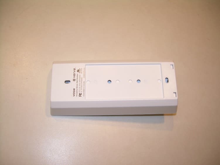
Click to zoom
Application Details
- Equipment Class
- DSC - Part 15 Security/Remote Control Transmitter
- Date of Grant
- Sep 10, 2012
- Application Purpose
- Original Equipment
- Date of Application
- Sep 10, 2012
- Equipment Note
- WALL-MOUNTED OCCUPANCY SENSOR
- Frequency Range
- 315.00000000 - 315.00000000
- Company
- EnOcean GmbH
- Country
- Germany
Documents & Files
Document Text
Text extracted from the exhibit documents filed with the FCC. Open a document above to read the original.
Users Manual
Occupancy Sensor - Wall Mounted Installation Guide Model: EOSW Package Contents ▪Occupancy Sensor ▪2 screws, 2 wall anchors ▪1 wide angle lens (installed) ▪1 long range lens Product Description The wall-mounted Occupancy Sensor saves energy and adds convenience by accurately detecting when an area is occupied or vacant. It is wireless, solar-powered, and uses a passive infrared (PIR) sensor to detect motion. The occupancy sensor transmits RF sig- nals that control lighting, HVAC, and outlets to manage building energy consumption more efficiently. Features Include: ▪Sends wireless signals to receiving devices whenever motion is detected ▪Harvests indoor light to power the sensor and wireless communications ▪Mounts flush on the wall or in a corner; adjustable ceiling corner bracket sold separately ▪Works with other sensors for enhanced occupancy tracking ▪Interchangeable lenses for tailored sensor coverage ▪Built-in tests to confirm operation at installed location ▪Supplemental battery or alternative power supply options for extreme low-light conditions Specifications Power SupplyIndoor light energy harvesting (Optional) Supplemental battery or 2-wire connector for external power or remote solar cell (3-5VDC) Transmission Range80 ft. (25 m) Radio FrequencyEnOcean 315 MHz, ISO/IEC 14545-3-10 standard Light Required to Sustain Operation 50 lux for 30 transmissions/hour 100 lux for 60 transmissions/hour Charge Time before Linking 2 minutes @ 50 lux Charge Time for Full Charge 3 hours @ 200 lux (after startup) 6 hours @ 200 lux (cold start) Operating Life in Dark- ness (after full charge) 48 hours EEP (EnOcean Equipment Profile) A05-07-01 Heartbeat 2 - 12 mins., randomized Dimensions5.83” L x 2.52” W x 1.8” D (148 mm x 64 mm x 45.7 mm) Weight4.09 oz. (116 g) EnvironmentIndoor use only 14° to 104°F (-10° to 40°C) 20% to 95% relative humidity (non-condensing) Agency ComplianceFCC, IC Functional Description If occupation is detected by the permanently active PIR sensor, a radio telegram indicating the occupied status will transmit immediately. An internal timer starts to run with a variable timer length. The timer value may vary between 60 and 300 seconds, depending on the light level. No radio telegrams will be sent out when the timer is counting down. After the timer has finished the countdown, the unit will trans- mit again if occupancy was detected during the countdown time period. If occupancy was not detected, the unit will transmit a heartbeat signal - sending the unoccupied status with a ran- dom timing of 2 to 12 minutes. There are two buttons which allow entrance to a “Walk” or “Light-level” test mode. These test modes are for installation purposes only and will be exited automatically after 3 minutes. Tools Required ▪Power drill, 3/16” bit ▪Screwdriver ▪Leveling tool ▪Light meter ▪Battery (CR2032) for testing Page 1 64mm 148mm 5.8” 2.5” Solar Cell Lens Button Interface 45.7mm 1.8” 28mm 1.1” Planning Take a moment to plan for the sensor’s successful operation and optimal communication with other system components. Remove the sensor from its packaging and place it under a bright light to provide the required startup charge. To quickly ensure the sensor energy storage is fully charged, insert a CR2032 battery for 30 seconds. ▪Ensure the location provides consistent and adequate light ▪Install with the appropriate lens for the required coverage ▪Locate the sensor between 8 and 10 ft (2.4 to 3 m) high with an unobstructed view of the space ▪For wide angle coverage, locate the sensor where traffic moves across the detection pattern, not in and out ▪Consider the area’s traffic patterns and principal use, for example, walking, lounging or sleeping ▪Provide a minimum clearance of 4 ft. (1.2 m) away from heat sources, light bulbs, forced air, or ventilation systems ▪Consider the construction materials (such as metal) in the space and obstacles that may interfere with RF signals Sensor Range A single occupancy sensor provides sufficient coverage for most applications. For some applications, multiple sensors may be required to provide complete coverage. Wide Angle Coverage 0 33 ft (10 m) 16 ft (5 m) 16 ft (5 m) Top View 6.8 ft (2.1 m) 6 ft15 ft 25 ft50 ft Side View 33 ft (10 m) Long Range Coverage 16 ft 0 16 ft 8 ft 8 ft Top View 27° 77° 21.5° 14° 6.5° center line Side View 6.8 ft (2.1 m) 3 ft (1 m) 7 ft (2.2 m) 10 ft (3 m) 35 ft (10.7 m) 60 ft (18.3 m) 100 ft (30.5 m) Installing The mounting plate can be installed flush to the wall or angled in a corner. NOTE: It may be easier to link the sensor before it is mounted on the wall. See the Linking section. 1. Remove the mounting plate from the sensor assembly by pressing the release tab located on the top of the sensor. 2. Using a level and a pencil, lightly mark two small dots to align the upper edge of the mounting plate. 3. Decide which of the two installation options is appropriate: A. Flush to the Wall i. Orient the mounting plate using the pencil marks. Mark the two mounting screw drill points. ii. Drill two holes with a 3/16” drill bit and insert the wall anchors. iii. Insert the first screw loosely and level the mounting plate. iv. Insert the second screw then hand-tighten the first screw. B. Angled in a Corner i. Orient the mounting plate using the pencil marks. ii. Carefully drill through two of the four blind holes on the angled sides of the mounting plate (one on each side). iii. Mark the two mounting screw drill points and drill two pilot holes with a 3/16” drill bit and insert the wall anchors. iv. Insert the two screws and hand-tighten them. 4. Fit the sensor into the groove at the bottom of the mounting plate and close the top. estimated time: 20 minutes Occupancy Sensor – Wall Mounted • Installation Guide Page 2 The sensor snaps into the tab at the top. 5. Confirm the sensor is properly positioned to detect motion and has sufficient light to operate, see the See Walk Test and See Light Test sections. Linking Two or more compatible d…
Text truncated - open the document above for the full version.
External Photos
Front View of the EUT Back View of the EUT
ID Label/Location Info
EOSW Occupancy Sensor, Wall-Mounted Made in China XEOSW01PL01A FCC ID: SZV-EOSW01 IC: 5713A-EOSW01 315 MHz
Internal Photos
View of the EUT with Back Cover Removed View of the EUT with Front Cover Removed View of the Back Side of the PCB View of the Front Side of the PCB
Test Report
Nemko-CCL, Inc. 1940 West Alexander Street Salt Lake City, UT 84119 801-972-6146 Test Report Certification Test Of: EOSW Test Specifications: FCC Part 15, Subpart C FCC ID #: SZV-EOSW01 Test Report Serial No: 207584-3.2 Applicant: EnOcean GmbH Kolpingring 18a Oberhaching 82041 Germany Date of Test: June 12, 2012 Report Issue Date: June 19, 2012 Accredited Testing Laboratory By: NVLAP Lab Code 100272-0 Nemko-CCL, Inc. TEST REPORT: 207584-3.2 REPORT ISSUE DATE: June 19, 2012 Page 2 of 29 CERTIFICATION OF ENGINEERING REPORT This report has been prepared by Nemko-CCL, Inc. to document compliance of the device described below with the certification requirements of FCC Part 15, Subpart C. This report may be reproduced in full. Partial reproduction of this report may only be made with the written consent of the laboratory. The results in this report apply only to the sample tested. - Applicant: EnOcean GmbH - Manufacturer: EnOcean GmbH - Brand Name: EnOcean - Model Number: EOSW - FCC ID #: SZV-EOSW01 On this 19 th day of June 2012, I, individually and for Nemko-CCL, Inc., certify that the statements made in this engineering report are true, complete, and correct to the best of my knowledge, and are made in good faith. Although NVLAP has accredited the Nemko-CCL, Inc. EMC testing facilities, this report must not be used to claim product certification, approval, or endorsement by NVLAP, NIST, or any agency of the federal government. Nemko-CCL, Inc. Tested by: Norman P. Hansen EMC Technician Nemko-CCL, Inc. TEST REPORT: 207584-3.2 REPORT ISSUE DATE: June 19, 2012 Page 3 of 29 TABLE OF CONTENTS PAGE SECTION 1.0 CLIENT INFORMATION .................................................................................4 SECTION 2.0 EQUIPMENT UNDER TEST (EUT) ..................................................................5 SECTION 3.0 TEST SPECIFICATION, METHODS & PROCEDURES .............................6 SECTION 4.0 OPERATION OF EUT DURING TESTING ..................................................10 SECTION 5.0 SUMMARY OF TEST RESULTS ...................................................................11 SECTION 6.0 MEASUREMENTS, EXAMINATIONS AND DERIVED RESULTS ..........12 APPENDIX 1 TEST PROCEDURES AND TEST EQUIPMENT ..........................................19 APPENDIX 2 PHOTOGRAPHS ................................................................................................22 Nemko-CCL, Inc. TEST REPORT: 207584-3.2 REPORT ISSUE DATE: June 19, 2012 Page 4 of 29 SECTION 1.0 CLIENT INFORMATION 1.1 Applicant: Company Name: EnOcean GmbH Kolpingring 18a Oberhaching 82041 Germany Contact Name: Armin Anders Title: Director Product Marketing 1.2 Manufacturer: Company Name: EnOcean GmbH Kolpingring 18a Oberhaching 82041 Germany Contact Name: Armin Anders Title: Director Product Marketing Nemko-CCL, Inc. TEST REPORT: 207584-3.2 REPORT ISSUE DATE: June 19, 2012 Page 5 of 29 SECTION 2.0 EQUIPMENT UNDER TEST (EUT) 2.1 Identification of EUT: Brand Name: EnOcean GmbH Model Number: EOSW Serial Number: None 2.2 Description of EUT: The EOSW is a wall mounted occupancy sensor for use in homes and businesses. The EOSW is integrated into the control/security system using a 315 MHz transmitter. The EOSW is powered by solar energy with a CR2032 battery for alternate/backup power. This report covers the transmitter circuitry of the device subject to FCC Part 15, Subpart C. The circuitry of the device, subject to FCC Part 15, Subpart B is covered in Nemko-CCL, Inc. report #207584-2.1. 2.3 EUT and Support Equipment: Brand Name Model Number FCC ID Number or Compliance Description Name of Interface Ports / Interface Cables BN: EnOcean MN: EOSW (Note 1) SN: None SZV-EOSW01 Sensor See Section 2.4 2.4 Interface Ports on EUT: There are no interface ports on the EUT. 2.5 Modification Incorporated/Special Accessories on EUT: There were no modifications or special accessories required to comply with the specification. Nemko-CCL, Inc. TEST REPORT: 207584-3.2 REPORT ISSUE DATE: June 19, 2012 Page 6 of 29 SECTION 3.0 TEST SPECIFICATION, METHODS & PROCEDURES 3.1 Test Specification: Title: FCC PART 15, Subpart C (47 CFR 15) Section 15.203 Section 15.231 Periodic operation in the band 40.66-40.70 MHz and above 70 MHz. Purpose of Test: The tests were performed to demonstrate initial compliance. 3.2 Methods & Procedures: 3.2.1 §15.203 An intentional radiator shall be designed to ensure that no antenna other than that furnished by the responsible party shall be used with the device. The use of a permanently attached antenna or of an antenna that uses a unique coupling to the intentional radiator shall be considered sufficient to comply with the provisions of this Section. The manufacturer may design the unit so that a broken antenna can be replaced by the user, but the use of a standard antenna jack or electrical connector is prohibited. This requirement does not apply to carrier current devices or to devices operated under the provisions of Sections 15.211, 15.213, 15.217, 15.219, or 15.221. Further, this requirement does not apply to intentional radiators that must be professionally installed, such as perimeter protection systems and some field disturbance sensors, or to other intentional radiators which, in accordance with Section 15.31(d), must be measured at the installation site. However, the installer shall be responsible for ensuring that the proper antenna is employed so that the limits in this Part are not exceeded. 3.2.2 §15.231 (a) The provisions of this section are restricted to periodic operation within the band 40.66-40.70 MHz and above 70 MHz. Except as Shown in paragraph (e) of this section, the intentional radiator is restricted to the transmission of a control signal such as those used with alarm systems, door openers, remote switches, etc. Radio control of toys is not permitted. Continuous transmissions, such as voice or video, and data transmissions are not permitted. The prohibition against data transmissions does not p…
Text truncated - open the document above for the full version.
Test Setup Photos
Front View Radiated Disturbance Worst Case Configuration Back View Radiated Disturbance Worst Case Configuration
Contact Information
Applicant
Armin Anders(Director Product Marketing)
Test Firm
VPI TechnologyJason Stewart
[email protected]801-495-2310
Technical Specifications
| # | Rule Parts | Frequency Range | Power Output |
|---|---|---|---|
| 1 | 15.231 | 315 MHz - 315 MHz | - |
Other Applications from EnOcean GmbH

SZV-PTM215U
Feb 04, 2021Temperature and Humidity Sensor with transmitter
Equipment Class
DSC - Part 15 Security/Remote Control Transmitter
SZV-STM550U
Feb 03, 2021Temperature and Humidity Sensor with transmitter
Equipment Class
DSC - Part 15 Security/Remote Control Transmitter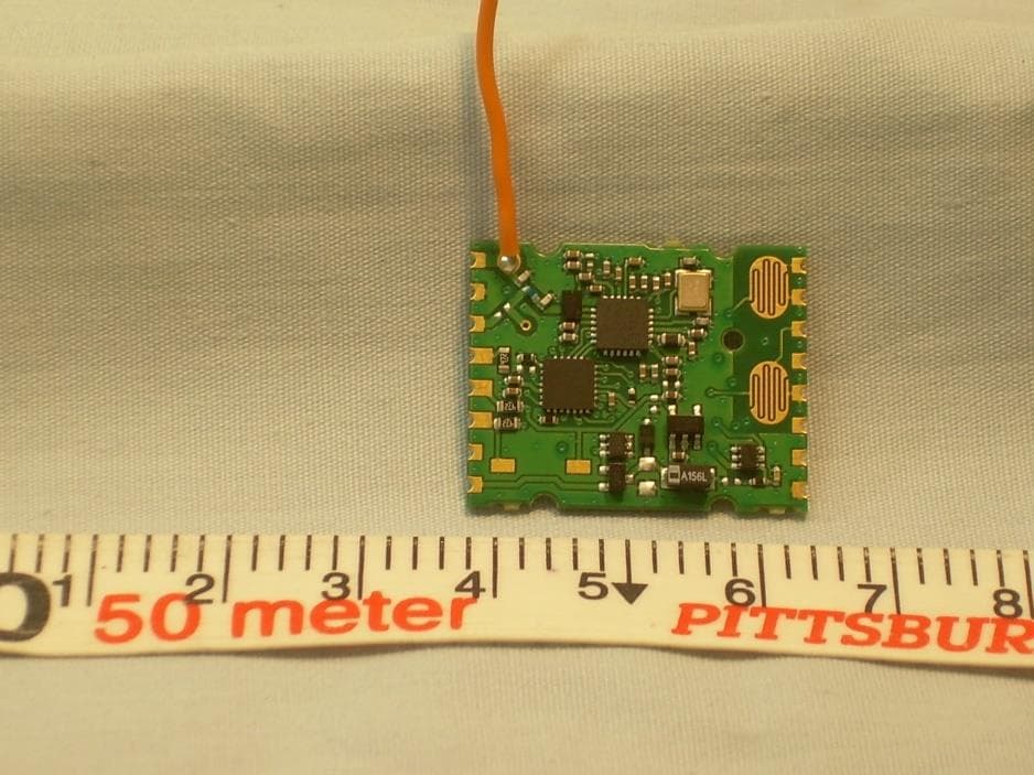
SZV-PTM535U
Sep 17, 2020Temperature and Humidity Sensor with transmitter
Equipment Class
DSC - Part 15 Security/Remote Control Transmitter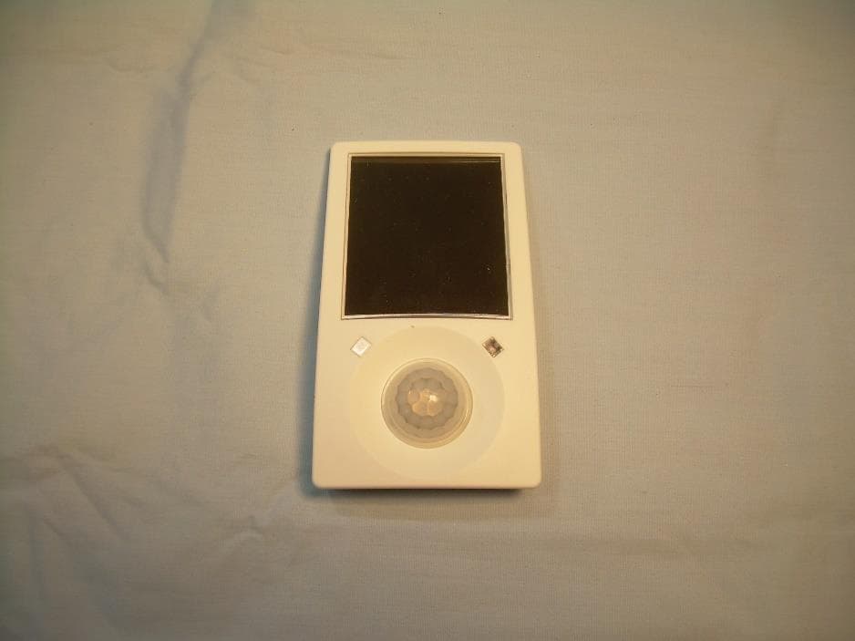
SZV-EMDCU
Mar 24, 2020Temperature and Humidity Sensor with transmitter
Equipment Class
DSC - Part 15 Security/Remote Control Transmitter
SZV-PTM215Z
Sep 16, 20132.405GHz - 2.475GHz transmitter
Equipment Class
DXX - Part 15 Low Power Communication Device Transmitter