SZV-PTM210CPushbutton Transmitter
EnOcean GmbH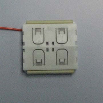
Click to zoom
Application Details
- Equipment Class
- DSR - Part 15 Remote Control/Security Device Transceiver
- Date of Grant
- Jul 08, 2010
- Application Purpose
- Original Equipment
- Date of Application
- Jul 08, 2010
- Equipment Note
- Pushbutton Transmitter
- Frequency Range
- 315.00000000 - 315.00000000
- Company
- EnOcean GmbH
- Country
- Germany
Documents & Files
Document Text
Text extracted from the exhibit documents filed with the FCC. Open a document above to read the original.
Users Manual
USER MANUAL V0.9 EnOcean GmbH Kolpingring 18a 82041 Oberhaching Germany Phone +49.89.67 34 689-0 Fax +49.89.67 34 689-50 [email protected] www.enocean.com Subject to modifications PTM 210 / PTM 210C User Manual V0.9 July 7, 2010 9:36 AM Page 1/18 Patent protected: US 6,747,573 US 7,019,241 Further patents pending Pushbutton Transmitter Device 315 MHz PTM 210 / 210C June 16, 2010 USER MANUAL V0.9 EnOcean GmbH Kolpingring 18a 82041 Oberhaching Germany Phone +49.89.67 34 689-0 Fax +49.89.67 34 689-50 [email protected] www.enocean.com Subject to modifications PTM 210 / PTM 210C User Manual V0.9 July 7, 2010 9:36 AM Page 2/18 PTM 210 / PTM 210C REVISION HISTORY The following major modifications and improvements have been made to the first version of this document: No Major Changes Published by EnOcean GmbH, Kolpingring 18a, 82041 Oberhaching, Germany www.enocean.com, [email protected], phone ++49 (89) 6734 6890 © EnOcean GmbH All Rights Reserved Important! This information describes the type of component and shall not be considered as assured characteristics. No responsibility is assumed for possible omissions or inaccuracies. Circuitry and specifications are subject to change without notice. For the latest product specifica- tions, refer to the EnOcean website: http://www.enocean.com. As far as patents or other rights of third parties are concerned, liability is only assumed for modules, not for the described applications, processes and circuits. EnOcean does not assume responsibility for use of modules described and limits its liability to the replacement of modules determined to be defective due to workmanship. Devices or systems containing RF components must meet the essential requirements of the local legal authorities. The modules must not be used in any relation with equipment that supports, directly or indirectly, human health or life or with applications that can result in danger for people, animals or real value. Components of the modules are considered and should be disposed of as hazardous waste. Local government regulations are to be observed. Packing: Please use the recycling operators known to you. By agreement we will take pack- ing material back if it is sorted. You must bear the costs of transport. For packing material that is returned to us unsorted or that we are not obliged to accept, we shall have to in- voice you for any costs incurred. USER MANUAL V0.9 EnOcean GmbH Kolpingring 18a 82041 Oberhaching Germany Phone +49.89.67 34 689-0 Fax +49.89.67 34 689-50 [email protected] www.enocean.com Subject to modifications PTM 210 / PTM 210C User Manual V0.9 July 7, 2010 9:36 AM Page 3/18 PTM 210 / PTM 210C TABLE OF CONTENT 1 GENERAL DESCRIPTION ................................................................................. 4 1.1 Basic Functionality......................................................................................... 4 1.2 Typical Applications ....................................................................................... 5 1.3 Technical Data .............................................................................................. 5 1.4 Mechanical Interface...................................................................................... 5 1.5 Environmental Conditions ..............................................................................10 1.6 Ordering Information ....................................................................................10 2 FUNCTIONAL DESCRIPTION ...........................................................................10 2.1 Block Diagram .............................................................................................10 2.2 Contact Nipples Designation ..........................................................................11 2.3 Transmission timing .....................................................................................12 3 APPLICATIONS INFORMATION........................................................................13 3.1 Laying the antenna (PTM210C only)................................................................13 3.2 Construction of application specific Switch Rockers............................................14 3.3 Device Mounting ..........................................................................................14 3.4 Transmission Range .....................................................................................15 4 AGENCY APPROVALS ....................................................................................16 4.1 CE Approval (PTM210 only) ...........................................................................16 4.2 FCC/IC Approval (PTM210C only) ...................................................................16 4.3 Japanese Type Approval (PTM210C only) .........................................................18 USER MANUAL V0.9 EnOcean GmbH Kolpingring 18a 82041 Oberhaching Germany Phone +49.89.67 34 689-0 Fax +49.89.67 34 689-50 [email protected] www.enocean.com Subject to modifications PTM 210 / PTM 210C User Manual V0.9 July 7, 2010 9:36 AM Page 4/18 PTM 210 / PTM 210C 1 GENERAL DESCRIPTION The radio transmitter device PTM 210 / PTM 210C from EnOcean enables the implementa- tion of wireless remote controls without batteries. Power is provided by a built-in electro- dynamic power generator. The PTM 210 / PTM 210C device serves the 868 MHz / 315 MHz air interface protocol of EnOcean. Electro-dynamic powered radio transmitter device PTM 210 1.1 Basic Functionality A common electro-dynamic energy transducer is actuated by a bow (1), which can be pushed from outside the device by an appropriate push button or switch rocker. When the energy bow is pushed down, electrical energy is created and an RF telegram is transmitted including a 32-bit device ID. Releasing the energy bow generates different telegram data, so every PTM telegram contains the information that the bow was pressed or released. “Long” or “Short” push button operation (the ti…
Text truncated - open the document above for the full version.
Block Diagram
Processor Base Band Filter Contact Nipples Energy Bow PowerConverter TX_BASE Pushed/Released Ant N S TX_DATA 315 MHz Colpits Osc. SAW based Modulator RF-Transistor DC Power Harmonics Filter PTM210C Block Diagram CONFIDENTIAL INFORMATION
External Photos
External Photos PTM210C Fig. 1: Near Top View Fig. 2: Near Bottom View Fig. 3: Far Top View Fig. 4: Far Bottom View
ID Label/Location Info
ID Label and Label Location PTM210C Fig. 1: ID Label Fig. 2: Label Location on Module
Internal Photos
Internal Photos PTM210C Fig. 1: Bottom Case including Fig. 2: Top Case including contact mat ECO200 and Energy Bows and flatspring Fig. 3: Top case parts disambled Fig. 4: PCB bottom view Fig. 5: PCB Top view
Operational Description
USER MANUAL V0.9 EnOcean GmbH Kolpingring 18a 82041 Oberhaching Germany Phone +49.89.67 34 689-0 Fax +49.89.67 34 689-50 [email protected] www.enocean.com Subject to modifications PTM 210 / PTM 210C User Manual V0.9 July 7, 2010 9:36 AM Page 1/18 Patent protected: US 6,747,573 US 7,019,241 Further patents pending Pushbutton Transmitter Device 315 MHz PTM 210 / 210C June 16, 2010 USER MANUAL V0.9 EnOcean GmbH Kolpingring 18a 82041 Oberhaching Germany Phone +49.89.67 34 689-0 Fax +49.89.67 34 689-50 [email protected] www.enocean.com Subject to modifications PTM 210 / PTM 210C User Manual V0.9 July 7, 2010 9:36 AM Page 2/18 PTM 210 / PTM 210C REVISION HISTORY The following major modifications and improvements have been made to the first version of this document: No Major Changes Published by EnOcean GmbH, Kolpingring 18a, 82041 Oberhaching, Germany www.enocean.com, [email protected], phone ++49 (89) 6734 6890 © EnOcean GmbH All Rights Reserved Important! This information describes the type of component and shall not be considered as assured characteristics. No responsibility is assumed for possible omissions or inaccuracies. Circuitry and specifications are subject to change without notice. For the latest product specifica- tions, refer to the EnOcean website: http://www.enocean.com. As far as patents or other rights of third parties are concerned, liability is only assumed for modules, not for the described applications, processes and circuits. EnOcean does not assume responsibility for use of modules described and limits its liability to the replacement of modules determined to be defective due to workmanship. Devices or systems containing RF components must meet the essential requirements of the local legal authorities. The modules must not be used in any relation with equipment that supports, directly or indirectly, human health or life or with applications that can result in danger for people, animals or real value. Components of the modules are considered and should be disposed of as hazardous waste. Local government regulations are to be observed. Packing: Please use the recycling operators known to you. By agreement we will take pack- ing material back if it is sorted. You must bear the costs of transport. For packing material that is returned to us unsorted or that we are not obliged to accept, we shall have to in- voice you for any costs incurred. USER MANUAL V0.9 EnOcean GmbH Kolpingring 18a 82041 Oberhaching Germany Phone +49.89.67 34 689-0 Fax +49.89.67 34 689-50 [email protected] www.enocean.com Subject to modifications PTM 210 / PTM 210C User Manual V0.9 July 7, 2010 9:36 AM Page 3/18 PTM 210 / PTM 210C TABLE OF CONTENT 1 GENERAL DESCRIPTION ................................................................................. 4 1.1 Basic Functionality......................................................................................... 4 1.2 Typical Applications ....................................................................................... 5 1.3 Technical Data .............................................................................................. 5 1.4 Mechanical Interface...................................................................................... 5 1.5 Environmental Conditions ..............................................................................10 1.6 Ordering Information ....................................................................................10 2 FUNCTIONAL DESCRIPTION ...........................................................................10 2.1 Block Diagram .............................................................................................10 2.2 Contact Nipples Designation ..........................................................................11 2.3 Transmission timing .....................................................................................12 3 APPLICATIONS INFORMATION........................................................................13 3.1 Laying the antenna (PTM210C only)................................................................13 3.2 Construction of application specific Switch Rockers............................................14 3.3 Device Mounting ..........................................................................................14 3.4 Transmission Range .....................................................................................15 4 AGENCY APPROVALS ....................................................................................16 4.1 CE Approval (PTM210 only) ...........................................................................16 4.2 FCC/IC Approval (PTM210C only) ...................................................................16 4.3 Japanese Type Approval (PTM210C only) .........................................................18 USER MANUAL V0.9 EnOcean GmbH Kolpingring 18a 82041 Oberhaching Germany Phone +49.89.67 34 689-0 Fax +49.89.67 34 689-50 [email protected] www.enocean.com Subject to modifications PTM 210 / PTM 210C User Manual V0.9 July 7, 2010 9:36 AM Page 4/18 PTM 210 / PTM 210C 1 GENERAL DESCRIPTION The radio transmitter device PTM 210 / PTM 210C from EnOcean enables the implementa- tion of wireless remote controls without batteries. Power is provided by a built-in electro- dynamic power generator. The PTM 210 / PTM 210C device serves the 868 MHz / 315 MHz air interface protocol of EnOcean. Electro-dynamic powered radio transmitter device PTM 210 1.1 Basic Functionality A common electro-dynamic energy transducer is actuated by a bow (1), which can be pushed from outside the device by an appropriate push button or switch rocker. When the energy bow is pushed down, electrical energy is created and an RF telegram is transmitted including a 32-bit device ID. Releasing the energy bow generates different telegram data, so every PTM telegram contains the information that the bow was pressed or released. “Long” or “Short” push button operation (the ti…
Text truncated - open the document above for the full version.
Parts List/Tune Up Info
Stückliste PTM210C BearbeiterS. Meineke PCB StatusNullserie (PTM210C-4_102) Zeichnungsnummer A18-L01-B01 Rev.6 Datum28.04.2009 BauteilBE-DescriptionKATEK-NrBE-SNR C1KON SMD 0402 6N8 +-5% 25V X7R90001073BFA5B00076020402 C2KON SMD 0603 1U +-10% X5R 16V (X7R 5% NICHT LIEFERBAR)90001075BFA5B00076020280 C3KON SMD 0402 33P +-5% 25V COG90001059BFA5B00021837792 C4KON SMD TANTAL A 10U +-10% 16V TAJA106K016R90002097BF C5KON SMD 0402 100P +-5% 25V COG90001057BFA5B00021837704 C6KON SMD 0402 100P +-5% 25V COG90001057BFA5B00021837704 C7KON SMD 0805 2U2 +-10% 16V X5R KERAMIK90001122BFA5B00075507718 C8KON SMD 0805 4U7 +-10% 10V X5R GRM21BR61A475KA73 90002271BF C9KON SMD 0402 100P +-5% 25V COG90001057BFA5B00021837704 C10KON SMD 0402 100P +-5% 25V COG90001057BFA5B00021837704 C11KON SMD 0402 0P56 +-0P1 50V NPO90002272BF C12KON SMD 0402 12P +-5% 25V COG90001087BFA5B00026918934 C13KON SMD 0402 1P +-0P1 25V COG90001091BFA5B00026918109 C14KON SMD 0402 100N +-10% 10V X5R GRM36X5R100N90001110BFA5B00026921574 C15n.b.------ C16KON SMD 0402 1N +-10% 25V X7R90001084BFA5B00021837847 C17KON SMD 0402 5P6 +-0P25 25V COG Keramik GRM36COG C1005COG90001106BFA5B00026917460 C18KON SMD 0402 12P +-5% 25V COG90001087BFA5B00026918934 C19KON SMD 0402 4P7 +-0P25 25V COG90001105BFA5B00021861959 C20KON SMD 0402 1P5 +-0P1 25V COG90001094BFA5B00026918087 C21KON SMD 0402 100P +-5% 25V COG90001057BFA5B00021837704 C22KON SMD 0402 470P +-5% 25V COG KERAMIK GRM1555C1H/C1005COG/B37627-K990001080BFA5B00075055862 C23KON SMD 0402 100P +-5% 25V COG90001057BFA5B00021837704 C24KON SMD 0402 100P +-5% 25V COG90001057BFA5B00021837704 D1SCHOTTKY-DIODE RB551V-30 ROHM SOD32390505305BF D2SCHOTTKY-DIODE RB551V-30 ROHM SOD32390505305BF D3Z-DIODE BZX884-B5V1 5.1V +-2% SMD SOD88490505375BF D4Z-DIODE BZX884-B5V1 5.1V +-2% SMD SOD88490505375BF IC1TPS62240DRV SON2x2-690505376BF IC2PIC16F610-I/ML QFN16 16PIN90505377BF J1FELDEFFEKT SI1912EDH-E3 VISHAY DUAL-N-CHANNEL 90505378BF L10R90301144BF L20R90301144BF L3DROSSEL 7440329002 2.2UH WE-LQ-GEHAEUSE 20% 0.79A RDC=0.126R 19500362BF L4Chip Drossel 74279205 1000OHM@100MHZ WE-CBF09901050BF L5IND SMD 0402 47NH +-5% WE-MK 74478447 WUERTH ELECTRONIC19500363BF L6IND SMD 0402 100NH +-5% WE-MK 744784101 WUERTH ELECTRONIC19500364BF L7IND SMD 0402 33NH +-5% WE-KI 744765133A WUERTH ELECTRONIC19500365BF Q1FILTER R2704 SAW-FILTER (RESONATOR) QCC8C 315MHZ 90700203BFA5B00075885601 R1WID SMD 0402 100K +-1% TK=10090301146BFA5B00026475304 R2WID SMD 0402 22K +-1% TK=10090301166BFA5B00021862135 R3WID SMD 0402 1M +-1% TK=10090301163BFA5B00026478241 R4WID SMD 0402 10K +-1% TK=10090301138BFA5B00021866117 R5WID SMD 0402 1M +-1% TK=10090301163BFA5B00026478241 R6WID SMD 0402 470K +-1% TK=10090301182BFA5B00075177053 R7WID SMD 0402 10K +-1% TK=10090301138BFA5B00021866117 R8WID SMD 0402 680K +-1% TK=10090301349BF R9WID SMD 0402 18K +-1% TK=10090301157BFA5B00026473060 R10WID SMD 0402 210K +-1% TK=10090301569BF R11WID SMD 0402 330R +-1% TK=10090301177BFA5B00021837484 R12WID SMD 0402 1K5 +-1% TK=10090301160BFA5B00026473049 R13WID SMD 0402 47K +-1% TK=10090301142BFA5B00026473346 R14WID SMD 0402 68K +-1% TK=10090301194BFA5B00026477416 R15WID SMD 0402 1M +-1% TK=10090301163BFA5B00026478241 R16WID SMD 0402 33R +-1% TK=10090300487BF R17WID SMD 0402 1K +-1% TK=100 90301140BFA5B00021866106 R18WID SMD 0402 1M +-1% TK=10090301163BFA5B00026478241 T1TRANS BC847S NPN-Array DUAL 45V/200mA G1010/4 90505020BFA5B00026017902 T2TRANS BFP420 NPN MIT 2 EMITTER 160MW 35MA 4.5V 10GHZ SELEKTIERT HFE 81-10190505253BFA5B00076041700 T3TRANS NPN BFP405 55MW 12MA 4.5V MIT 2 EMITTER RF 12GHZ SELEKTIERT HFE 81-10190505256BFA5B00076060072 T4TRANS NPN BFP405 55MW 12MA 4.5V MIT 2 EMITTER RF 12GHZ SELEKTIERT HFE 81-10190505256BFA5B00076060072 T5TRANS BC847S NPN-Array DUAL 45V/200mA G1010/4 90505020BFA5B00026017902
Schematics
02.07.2010 10:01:24 f=2.00 N:\4 Projekte\41 Gebäudetechnik und Industrie\41-16 PTM 210\41-16-2 Elektronik\41-16-25 Nullserie Gerätezustand x\41-16-251 EDA-Daten (E agle und Protel)\PTM210C\PTM210C.brd
Schematics
02.07.2010 09:58:27 f=2.00 N:\4 Projekte\41 Gebäudetechnik und Industrie\41-16 PTM 210\41-16-2 Elektronik\41-16-25 Nullserie Gerätezustand x\41-16-251 EDA-Daten (E agle und Protel)\PTM210C\PTM210C.brd
Schematics
DRAWNCHECKEDENG APPRMGR APPR UNLESS OTHERWISE SPECIFIED DIMENSIONS ARE IN MILLIMETERS ANGLES ±X.X° 2 PL ±X.XX 3 PL ±X.XXX NAME SM DATE 08/19/09 SOLID EDGE UGS - The PLM Company TITLE PTM210C Bauschaltplan (Top) SIZE A2 DWG NO A18-L01-B03-top-5 REV 5 FILE NAME: A18-L01-B03-top-5.dftSCALE: WEIGHT: SHEET 1 OF 1 REVISION HISTORY REV DESCRIPTION DATE APPROVED S30851-S3031-A210 C1 C2 L1 A1 C2 A2 L2 A1 C3 A2 L3 A2 C4 A3 L4 A2 C5 B3 L5 B3 C6 C3 L6 C3 C7 A3 L7 C3 C8 A2 Q1 B3 C9 A3 R1 C2 C10 C3 R2 C2 C11 C3 R3 C1 C12 C3 R4 C2 C13 A3 R5 C2 C14 C2 R6 C3 C15 A3 R7 C2 C16 C2 R8 A2 C17 C3 R9 C3 C18 C3 R10 A2 C19 B3 R11 B3 C20 C3 R12 A3 C21 C2 R13 A3 C22 C3 R14 B3 C23 A3 R15 B2 C24 B3 R16 A3 D1 A3 R17 C2 D2 A3 R18 B2 D3 C1 T1 C2 D4 C1 T2 C3 IC1 A2 T3 B3 IC2 C2 T4 B3 J1 A1 T5 C3
Test Report
This document was signed electronically. The Center for Quality Engineering of SGS Germany GmbH is accredited by DATech for COMPONENTS TESTING ENVIRONMENTAL ENGINEERING ELECTROMAGNETIC COMPATIBILITY PRODUCT SAFETY TELECOM CONFORMANCE TESTS SGS Germany GmbH, SGS CQE, Hofmannstr. 50, D-81379 München, Phone +49 89-787475-130, Fax +49 89-787475-122, Internet www.sgs-cqe.de The test report shall not be reproduced except in full without the written approval of the testing laboratory DAT-P-002/91-02 Center for Quality Engineering Test Report No.: D0TE0001 FCC ID: SZV-PTM210C IC ID: 5713A-PTM210C Order No.: D0TE Pages: 29 Munich, Jul 02, 2010 Client: EnOcean GmbH Equipment Under Test: Transmitter Module PTM210C Manufacturer: EnOcean GmbH Task: Conformance test according to the test specifications mentioned below Test Specification(s): FCC 47 CFR Part 15 IC RSS-210 Result: The EUT complies with the requirements of the specification. The results relate only to the items tested as described in this test report. approved by: Date Signature Neuhäusler Lab Manager Wireless & Software Jul 02, 2010 Bauer Lab Manager EMC Jul 02, 2010 Test Report No.: D0TE0001 Date: Jul 02, 2010 Transmitter Module PTM210C page 2 / 29 The test report shall not be reproduced except in full without the written approval of the testing laboratory CONTENTS 1 Summary ..................................................................................................................................4 2 References ...............................................................................................................................5 2.1 Specifications ......................................................................................................................5 2.2 Glossary of Terms...............................................................................................................5 3 General Information ................................................................................................................6 3.1 Identification of Client..........................................................................................................6 3.2 Test Laboratory ...................................................................................................................6 3.3 Time Schedule ....................................................................................................................6 3.4 Participants .........................................................................................................................6 4 Equipment Under Test ............................................................................................................7 4.1 Description of EUT ..............................................................................................................7 4.2 Configuration of EUT...........................................................................................................8 4.3 Operating Conditions ..........................................................................................................8 4.4 Compliance Criteria.............................................................................................................8 5 General Description of Tests..................................................................................................9 5.1 Tested Carrier Frequencies ................................................................................................9 5.2 Calibration of the Test Equipment.......................................................................................9 6 Test Results ...........................................................................................................................10 6.1 Test No. 1: Conducted Emissions ([1] § 15.207) ..............................................................10 6.2 Test No. 2: Field strength correction for pulse operation (Duty Cycle) ([1] § 15.35(c)) .....10 6.2.1 Purpose ......................................................................................................................10 6.2.2 Limits ..........................................................................................................................10 6.2.3 EUT Operating Condition ...........................................................................................10 6.2.4 Test Configuration ......................................................................................................10 6.2.5 Test Procedure and Results .......................................................................................11 6.2.6 Test Protocol ..............................................................................................................11 6.3 Test No. 3: Field strength of the fundamental wave ([1] § 15.231(b), [3] A1.1.2) .............13 6.3.1 Purpose ......................................................................................................................13 6.3.2 Limits ..........................................................................................................................13 6.3.3 EUT Operating Condition ...........................................................................................13 6.3.4 Test Configuration ......................................................................................................13 6.3.5 Test Procedure and Results .......................................................................................14 6.3.6 Test Protocol ..............................................................................................................14 6.4 Test No. 4: Radiated Emissions (9kHz – 30MHz) ([1] § 15.209; [3] T1, 3) .......................15 6.4.1 Purpose ......................................................................................................................15 Test Report No.: D0TE0001 Date: Jul 02, 2010 Transmitter Module PTM210C page 3 / 29 The test report shall …
Text truncated - open the document above for the full version.
Test Setup Photos
The Center for Quality Engineering of SGS Germany GmbH is accredited by DATech for COMPONENTS TESTING ENVIRONMENTAL ENGINEERING ELECTROMAGNETIC COMPATIBILITY PRODUCT SAFETY TELECOM CONFORMANCE TESTS SGS Germany GmbH, SGS CQE, Hofmannstr. 50, D-81379 München, Phone +49 89-787475-130, Fax +49 89-787475-122, Internet www.sgs-cqe.de Test Setup Photos - Field strength correction for pulse operation (Duty Cycle) (§ 15.35(c)) and - Emission Bandwidth (§ 15.231(c)) and - Transmit Duration (§ 15.231(a)): - Field strength of the fundamental wave (§ 15.231(b)): 2/2 - Radiated Emissions (9kHz – 30MHz) (§ 15.209): - Radiated Emissions (30MHz – 1GHz) (§ 15.209, 231(b)): - Radiated Emissions (1GHz – 4GHz) (§ 15.209, 231(b)):
Contact Information
Applicant
Armin Anders(Director Product Marketing)
Test Firm
SGS Germany GmbHJosef Bauer
Technical Specifications
| # | Rule Parts | Frequency Range | Power Output |
|---|---|---|---|
| 1 | 15.231 | 315 MHz - 315 MHz | - |
Other Applications from EnOcean GmbH

SZV-PTM215U
Feb 04, 2021Temperature and Humidity Sensor with transmitter
Equipment Class
DSC - Part 15 Security/Remote Control Transmitter
SZV-STM550U
Feb 03, 2021Temperature and Humidity Sensor with transmitter
Equipment Class
DSC - Part 15 Security/Remote Control Transmitter
SZV-PTM535U
Sep 17, 2020Temperature and Humidity Sensor with transmitter
Equipment Class
DSC - Part 15 Security/Remote Control Transmitter
SZV-EMDCU
Mar 24, 2020Temperature and Humidity Sensor with transmitter
Equipment Class
DSC - Part 15 Security/Remote Control Transmitter
SZV-PTM215Z
Sep 16, 20132.405GHz - 2.475GHz transmitter
Equipment Class
DXX - Part 15 Low Power Communication Device Transmitter