SZV-STM300UTRANSCEIVER MODULE
EnOcean GmbH
Click to zoom
Application Details
- Equipment Class
- DSC - Part 15 Security/Remote Control Transmitter
- Date of Grant
- Feb 26, 2013
- Application Purpose
- Original Equipment
- Date of Application
- Feb 26, 2013
- Equipment Note
- TRANSCEIVER MODULE
- Frequency Range
- 902.87500000 - 902.87500000
- Company
- EnOcean GmbH
- Country
- Germany
Documents & Files
Document Text
Text extracted from the exhibit documents filed with the FCC. Open a document above to read the original.
Users Manual
USER MANUAL EnOcean GmbH Kolpingring 18a 82041 Oberhaching Germany Phone +49.89.67 34 689-0 Fax +49.89.67 34 689-50 [email protected] www.enocean.com Subject to modifications STM 300 / STM 300C / STM 300U User Manual V1.34 February 14, 2013 Page 1/41 Patent protected: WO98/36395, DE 100 25 561, DE 101 50 128, WO 2004/051591, DE 103 01 678 A1, DE 10309334, WO 04/109236, WO 05/096482, WO 02/095707, US 6,747,573, US 7,019,241 Observe precautions! Electrostatic sensitive devices! Scavenger Transceiver Module STM 300 / STM 300C / STM 300U February 14 th , 2013 USER MANUAL 1.34 © 2013 EnOcean | www.enocean.com STM 300 / STM 300C / STM 300U User Manual | Page 2/41 STM 300 / STM 300C / STM 300U REVISION HISTORY The following major modifications and improvements have been made to the first version of this document: No Major Changes 1.01 Tape running direction added in 3.8 1.10 Application note for multiple digital inputs with WAKE functionality added. 1.20 Error corrected in 3.5.1. and 4.1: Maximum gain of external antenna at 50 Ohm output RF_50 is 0 dBi! 1.25 Charging circuit in 3.1 corrected; remarks added regarding use of IOVDD in 2.3. Parameters of A/D converter corrected and specified in more detail in 2.3.2 1.26 Optional resolution at ADIO0, ADIO1, ADIO2 corrected in 2.3. Detailed description in 2.9.1 was correct! 1.30 New improved application note in 3.1, which avoids deep discharge of the long term storage. 1.31 Updated data on conducted output power in 1.2; improved layout recommenda- tions in 3.6 1.32 Antenna recommendations removed and referred to external application note AN102, and AN105; Maximum Rating for IOVDD modified (IOVDD may now exceed VDD); Chapter “Related Documents” added. Figure added in 3.3.1; parameters for antenna requirements relaxed in 4.5.1. 1.33 Added STM 300U (902.875 MHz), new product image 1.34 Updated Agency certifications according to FCC / IC requirements Published by EnOcean GmbH, Kolpingring 18a, 82041 Oberhaching, Germany www.enocean.com, [email protected], phone +49 (89) 6734 6890 © EnOcean GmbH All Rights Reserved Important! This information describes the type of component and shall not be considered as assured characteris- tics. No responsibility is assumed for possible omissions or inaccuracies. Circuitry and specifications are subject to change without notice. For the latest product specifications, refer to the EnOcean web- site: http://www.enocean.com. As far as patents or other rights of third parties are concerned, liability is only assumed for modules, not for the described applications, processes and circuits. EnOcean does not assume responsibility for use of modules described and limits its liability to the replacement of modules determined to be defective due to workmanship. Devices or systems contain- ing RF components must meet the essential requirements of the local legal authorities. The modules must not be used in any relation with equipment that supports, directly or indirectly, human health or life or with applications that can result in danger for people, animals or real value. Components of the modules are considered and should be disposed of as hazardous waste. Local government regulations are to be observed. Packing: Please use the recycling operators known to you. USER MANUAL 1.34 © 2013 EnOcean | www.enocean.com STM 300 / STM 300C / STM 300U User Manual | Page 3/41 STM 300 / STM 300C / STM 300U TABLE OF CONTENT 1 MODULE VARIANTS AND RELATED DOCUMENTS ............................................... 4 2 GENERAL DESCRIPTION ................................................................................. 4 2.1 Basic functionality ......................................................................................... 4 2.2 Technical data ............................................................................................... 5 2.3 Physical dimensions ....................................................................................... 6 2.4 Environmental conditions ............................................................................... 6 2.5 Ordering Information ..................................................................................... 7 3 FUNCTIONAL DESCRIPTION ............................................................................ 8 3.1 Simplified firmware flow chart and block diagram .............................................. 8 3.2 Hardware pin out ........................................................................................... 9 3.3 Pin description and operational characteristics ................................................. 10 3.3.1 GPIO supply voltage ................................................................................ 12 3.3.2 Analog and digital inputs .......................................................................... 13 3.4 Absolute maximum ratings (non operating) .................................................... 14 3.5 Maximum ratings (operating) ........................................................................ 14 3.6 Power management and voltage regulators .................................................... 14 3.7 Charge control output (CCO) ......................................................................... 15 3.8 Configuration .............................................................................................. 16 3.8.1 Configuration via pins .............................................................................. 16 3.8.2 Configuration via programming interface .................................................... 17 3.9 Radio telegram ............................................................................................ 18 3.9.1 Normal operation ..................................................................................... 18 3.9.2 Teach-in telegram ................................................................................... 19 3.10 Transmit timing .....................................................…
Text truncated - open the document above for the full version.
Users Manual
USER MANUAL EnOcean GmbH Kolpingring 18a 82041 Oberhaching Germany Phone +49.89.67 34 689-0 Fax +49.89.67 34 689-50 [email protected] www.enocean.com Subject to modifications TCM 300 / TCM 320 User Manual 10 February 6 th , 2013 Page 1/53 Patent protected: WO98/36395, DE 100 25 561, DE 101 50 128, WO 2004/051591, DE 103 01 678 A1, DE 10309334, WO 04/109236, WO 05/096482, WO 02/095707, US 6,747,573, US 7,019,241 Observe precautions! Electrostatic sensitive devices! Transceiver Module TCM 300 / TCM 300C / TCM 300U TCM 320 / TCM 320C / TCM 320U February 6 th , 2013 USER MANUAL © 2013 EnOcean | www.enocean.com TCM 300x / TCM 320x User Manual | Page 2/53 TCM 300 / TCM 300C / TCM 300U TCM 320 / TCM 320C / TCM 320U REVISION HISTORY The following major modifications and improvements have been made to the first version of this document: No Major Changes 1.01 Tape running direction added in 3.8 1.02 Dimension of TCM 320 corrected (width 18 mm instead of 19 mm) 1.03 Editorial changes 1.10 Timing information regarding serial protocol added in A.2, A.3. 0xFFFF_FFFF ex- cluded from usable ID range, because this ID will be used as broadcast ID. 1.20 Error corrected in 3.2.1. and 4.1: Maximum gain of external antenna at 50 Ohm output RF_50 is 0 dBi! Error corrected in 2.2: WXODIO is configured as output and provides information on VON signal 1.21 Note added in 3.5 1.25 Remarks added regarding use of IOVDD in 2.2.; Antenna specification in 3.3.1 ex- tended. Updated information on conducted output power in 1.2; A.2.2 changed to point to EnOcean Alliance Website; A.2.3 and A.2.4 removed; editorial changes 1.26 Start-up time added in 1.2; Layout recommendations improved in 3.6 1.27 Antenna recommendations removed and referred to application note AN102 and AN105; Maximum Rating for IOVDD modified (IOVDD may now exceed VDD); Chapter “Related Documents” added; figure added in 3.2.1; parameters for anten- na requirements relaxed in 4.2.1.; pin numbers added in 3.2; Update of FCC grants in 5.2; TCM 320 drawing modified in 2.3. 1.29 New module variants for 902.875 MHz 1.30 Several Changes to meet FCC and IC manual requirements for Limited Modular Approval Published by EnOcean GmbH, Kolpingring 18a, 82041 Oberhaching, Germany www.enocean.com, [email protected], phone +49 (89) 6734 6890 © EnOcean GmbH All Rights Reserved Important! This information describes the type of component and shall not be considered as assured characteris- tics. No responsibility is assumed for possible omissions or inaccuracies. Circuitry and specifications are subject to change without notice. For the latest product specifications, refer to the EnOcean web- site: http://www.enocean.com. As far as patents or other rights of third parties are concerned, liability is only assumed for modules, not for the described applications, processes and circuits. EnOcean does not assume responsibility for use of modules described and limits its liability to the replacement of modules determined to be defective due to workmanship. Devices or systems contain- ing RF components must meet the essential requirements of the local legal authorities. The modules must not be used in any relation with equipment that supports, directly or indirectly, human health or life or with applications that can result in danger for people, animals or real value. Components of the modules are considered and should be disposed of as hazardous waste. Local government regulations are to be observed. Packing: Please use the recycling operators known to you. USER MANUAL © 2013 EnOcean | www.enocean.com TCM 300x / TCM 320x User Manual | Page 3/53 TCM 300 / TCM 300C / TCM 300U TCM 320 / TCM 320C / TCM 320U TABLE OF CONTENT 1 MODULE VARIANTS AND RELATED DOCUMENTS ............................................... 5 2 GENERAL DESCRIPTION ................................................................................. 6 2.1 Basic functionality ......................................................................................... 6 2.2 Technical data TCM 300 / TCM 320 (868.300 MHz) ............................................ 7 2.3 Technical data TCM 300C / TCM 320C (315.000 MHz) ........................................ 8 2.4 Technical data TCM 300U/ TCM 320U (902.875 MHz) ......................................... 8 2.5 Physical dimensions TCM 300x ........................................................................ 9 2.6 Physical dimensions TCM 320x ........................................................................ 9 2.7 Environmental conditions ............................................................................. 10 2.8 Ordering information .................................................................................... 10 3 FUNCTIONAL DESCRIPTION .......................................................................... 11 3.1 Pin out ....................................................................................................... 11 3.2 Pin description and operational characteristics ................................................. 12 3.2.1 GPIO supply voltage - IOVDD .................................................................... 14 3.3 Absolute maximum ratings (non operating) .................................................... 15 3.4 Maximum ratings (operating) ........................................................................ 15 3.5 Operating modes ......................................................................................... 16 3.6 Mode selection ............................................................................................ 17 3.7 Repeater configuration ................................................................................. 18 3.8 Teach-in procedure ...................................................................................... 19 3.8.1 Setting the receiver to learning mode ........................................................ 19 3.8.2 Confirmation of Learning Mode ..............................…
Text truncated - open the document above for the full version.
Users Manual
USER MANUAL V1.07 EnOcean GmbH Kolpingring 18a 82041 Oberhaching Germany Phone +49.89.67 34 689-0 Fax +49.89.67 34 689-50 [email protected] www.enocean.com Subject to modifications TCM 310 / 310C / TCM 310U User Manual February 14, 2013 Page 1/26 Patent protected: WO98/36395, DE 100 25 561, DE 101 50 128, WO 2004/051591, DE 103 01 678 A1, DE 10309334, WO 04/109236, WO 05/096482, WO 02/095707, US 6,747,573, US 7,019,241 Observe precautions! Electrostatic sensitive devices! Transceiver Module TCM 310 / TCM 310C / TCM 310U February 14 th , 2013 USER MANUAL V1.07 © 2013 EnOcean | www.enocean.com TCM 310 / TCM 310C / TCM 310U User Manual V1.07 | Page 2/26 TCM 310 / TCM 310C / TCM 310U REVISION HISTORY The following major modifications and improvements have been made to the first version of this document: No Major Changes 1.00 Initial version 1.01 Modification for Step Code DB; increased number of filters and Smart Ack mail- boxes 1.02 Supply voltage range extended 1.03 Start-up time and current consumption in deep sleep mode added in 1.2; im- proved layout recommendations in 3.5 1.04 Antenna recommendations removed and referred to application note AN102 and AN105; Maximum Rating for IOVDD modified (IOVDD may now exceed VDD); Ad- ditional information in 3.6; Chapter “Related Documents” added; pin numbers added in 3.2; update of FCC grant in 5.2; parameters for antenna requirements relaxed in 4.2.1.; 1.05 Error in table in 3.2 corrected (pin 17 and 18 need to be connected to GND as shown in figure above) 1.06 Supply voltage range extended; start-up time from sleep added 1.07 Added TCM 310U Published by EnOcean GmbH, Kolpingring 18a, 82041 Oberhaching, Germany www.enocean.com, [email protected], phone +49 (89) 6734 6890 © EnOcean GmbH All Rights Reserved Important! This information describes the type of component and shall not be considered as assured characteris- tics. No responsibility is assumed for possible omissions or inaccuracies. Circuitry and specifications are subject to change without notice. For the latest product specifications, refer to the EnOcean web- site: http://www.enocean.com. As far as patents or other rights of third parties are concerned, liability is only assumed for modules, not for the described applications, processes and circuits. EnOcean does not assume responsibility for use of modules described and limits its liability to the replacement of modules determined to be defective due to workmanship. Devices or systems contain- ing RF components must meet the essential requirements of the local legal authorities. The modules must not be used in any relation with equipment that supports, directly or indirectly, human health or life or with applications that can result in danger for people, animals or real value. Components of the modules are considered and should be disposed of as hazardous waste. Local government regulations are to be observed. Packing: Please use the recycling operators known to you. USER MANUAL V1.07 © 2013 EnOcean | www.enocean.com TCM 310 / TCM 310C / TCM 310U User Manual V1.07 | Page 3/26 TCM 310 / TCM 310C / TCM 310U TABLE OF CONTENT 1 MODULE VARIANTS AND RELATED DOCUMENTS ............................................... 4 2 GENERAL DESCRIPTION ................................................................................. 4 2.1 Basic functionality ......................................................................................... 4 2.2 Technical data ............................................................................................... 5 2.3 Physical dimensions ....................................................................................... 6 2.4 Environmental conditions ............................................................................... 6 2.5 Ordering information ..................................................................................... 6 3 FUNCTIONAL DESCRIPTION ............................................................................ 7 3.1 Pin out ......................................................................................................... 7 3.2 Pin description and operational characteristics .................................................. 7 3.2.1 GPIO supply voltage - IOVDD ...................................................................... 8 3.3 Absolute maximum ratings (non operating) ...................................................... 8 3.4 Maximum ratings (operating) .......................................................................... 8 3.5 System environment ...................................................................................... 8 3.6 Serial Interface ............................................................................................. 9 3.7 Built-in Repeater ......................................................................................... 10 3.8 Smart Acknowledge ..................................................................................... 10 3.9 Remote Management ................................................................................... 11 4 APPLICATIONS INFORMATION....................................................................... 11 4.1 Transmission range ..................................................................................... 11 4.2 Antenna options .......................................................................................... 12 4.2.1 Overview ................................................................................................ 12 4.2.2 Whip antenna ......................................................................................... 12 4.2.3 Helical antenna ....................................................................................... 13 4.3 Recommendations for laying a whip antenna .................................................. 14 4.4 Power supply requirements ........................................................................... 15 4.5 Layout recomme…
Text truncated - open the document above for the full version.
Cover Letter(s)
Enoc€n GmbH, Kolpingring 1Ba, D-82041 Offi)adring Timco Engineering 849 N.W. State Road 45 PO Box 370 Newberry, FL 32669 Attn: Director of Certification Enoean GmbH Kolpingring 18a D-82041 Oberhaching www.enocean.com Oliver Sczesny Dipl.Ing. ( FH) Application Engineering Manager rel +1 (801) 3r2 OLLT mobil +1 (801) 989 0240 oliver.sczesn [email protected] Authoritv to Act as Aqent- FCC On our behalf, I authorize Tom Jackson, General Manager, or Merry Jackson, Office Manager, of Nemko-CCL, Inc. at 1940 W. Alexander Street, Salt Lake City, UT 84119, to act as our agent in the preparation of this application for equipment certification. I certify that submitted documents properly describe the device or system for which equipment certification is sought. I also certify that each unit manufactured, imported or marketed, as defined in Federal Communications Commission regulations will have affixed to it a label identicalto that submitted for approval with this application. In signing this letter, Applicant certifies that neither the applicant nor any party to the application is subject to a denial of Federal benefits, that include FCC benefits, pursuant to Section 5301 of the Anti- Drug Abuse Act of 1988, 21 U.S.C. S 862 because of a conviction for possession or distribution of a controlled substance. See 47 CFR 1 .2002(b) for the definition of a "party" for these purposes. For instances where our authorized agent signs the application for certification on our behalf, I acknowledge that all responsibility for complying with the terms and conditions for certification, as specified by Timco Engineering still resides with EnOcean GmbH at Kolpingring 18a, Oberhaching 82041, Germany. Dated this 14thDay of January 2013 Agency agreement expiration date:December 312013 Oliver Sczesny Printed Title: ApplicationEngineeringManager On behalf of : Telephone: EnOcean GmbH +1 (801) 312 0117 Engcean GmbH, Kolpingring 18a, D-82041 Oberhaching I Geschziftsfllhrer: Laurent Giai-l4iniet und Uwe Thumm I Registergericht l4unchen, HRB 139781 I TFI +4q Rq 67 ?4 6Rq - n I Fay +4q 3q 67 ?4 6Aq - 54 | infnfilpnmcan.nm I Hvnn\/FrainshtnL Miinrhe^ Al7 -7i )^:t)Jn kh )44O6'1i
Cover Letter(s)
EnOceanGmbHKolpingring18a82041Oberhaching/Germany II To: FederalCommunicationsCommission OfficeofEngineeringandTechnology.LaboratoryDivision 7435OaklandMillsRd. Columbia,MD21046-1609 LaurentGiai-Miniet ChiefExecutiveOfficer Phone+49.89.6734'689-0 Fax+49.89.6734689-50 [email protected] Reference:SignatureAuthorizationforFCCCertifications ToWhomIt MayConcern: ThisAuthorizationwilldesignatethepersonnamedbelowtoaetonmy behalfandEnOcean'sbehalfasauthorizedagentandrepresentativeuntil furthernotice.Allactscan:ted.outandrequests.mad.ebythisnamed. representativerelatingtoanymatterbeforetheFCC,includingrequests fortOnfide'ntiäl"ity,shallhavethesameeffectasmine. Name: Title: Address: Telephone: Fax: Email: OliverSczesny ApplicationEngineeringManager 6914S.3000E.; CottonwoodHeights,UTi84121,U.S.Ä. +1(801)3120117 n.a. [email protected] QuestionsaboutthescopeandeffeetofthisAuthorizationshouldbe addressedasfolIows: Name: Title: Address: Telephone: Fax: Em'il: L LaurentGial-Miniet CEO Kolpingring18a,84021Oberhaching,Germany +49(89)6734689- 0 +(89)6734689- 50 [email protected] EnOceanGmbH Kolpingring183 82041Oberhaching Phone+49.89.6734689-0 Fax+49.89.6734689-50 [email protected] ManagingDirec!ors:Lauren!Giai-Minie!, UweThumm Regis!eredCourtMunichHRB139781 Account: HypoVereinsbankMünchen No.2440610
Cover Letter(s)
EnOcean GmbH | Kolpingring 18a | 82041 Oberhaching | Germany FCC Application for FCC ID: SZV-STM300U Subject: Frequency Update on FCC Grant To Whom it May Concern: In the initial submission for FCC ID: SZV-STM300U the frequency of the low power transmitter was rounded up to one decimal point showing the transmitter at 902.9 MHz. This letter is to request that the FCC Grant for FCC ID: SZV- STM300U be updated to show the frequency of the low power transmitter with three decimal points showing the transmitter at 902.875MHz. Since all other related documentation, including Datasheet and User Manual, which have been part of the initial submission, are showing 902.875MHz, some customers have become confused about the frequency in use. By doing this we believe that this more accurately reflects the actual frequency being transmitted. Sincerely yours, Armin Anders Co-Founder & VP Business Development EnOcean GmbH Kolpingring 18a 82041 Oberhaching Germany www.EnOcean.com [email protected] Armin Anders Co Founder & VP Business Development [email protected] Date 16. Nov. 2016 Managing Director Dr. Wald Siskens Registered Court Munich HRB 139781 VAT Reg.No. DE813355588 Account HypoVereinsbank München IBAN DE19700202700002440610 BIC HYVEDEMMXXX Federal Communications Commission Authorization and Evaluation Division 1435 Oakland Mills Road Columbia, MD 21046
External Photos
Front View of the EUT (Shown with Helical Antenna) Back View of the EUT
ID Label/Location Info
16mm Model: STM 300U D300-1 CA 03/13 161103008367 12 mm IC: 5713A- STM300U FCC ID: SZV-STM300U Model: TCM 300U K300-1 CA 03/13 161103008367 12 mm IC: 5713A- STM300U FCC ID: SZV-STM300U 16mm Model: TCM 310U K310-1 CA 03/13 161103008367 2 12 mm IC: 5713A- STM300U FCC ID: SZV-STM300U 16mm
ID Label/Location Info
Label Location
Internal Photos
Front View of the EUT (Shown with Helical Antenna) Back View of the EUT Circuitry Under RF Shield
Test Report
Nemko-CCL, Inc. 1940 West Alexander Street Salt Lake City, UT 84119 801-972-6146 Test Report Certification Test Of: TCM 300U, TCM 310U, and STM 300U FCC ID: SZV-STM300U Test Specifications: FCC Part 15, Subpart C Test Report Serial No: 224951-2.2 Applicant: EnOcean GmbH Kolpingring 18a Oberhaching 82041 Germany Dates of Test: November 19 and 26, 2012 Issue Date: January 3, 2013 Accredited Testing Laboratory By: NVLAP Lab Code 100272-0 Nemko-CCL, Inc. TEST REPORT: 224951-2.2 ISSUE DATE: 1/3/2013 Page 2 of 35 CERTIFICATION OF ENGINEERING REPORT This report has been prepared by Nemko-CCL, Inc. to document compliance of the device described below with the certification requirements of FCC Part 15, Subpart C. This report may be reproduced in full. Partial reproduction of this report may only be made with the written consent of the laboratory. The results in this report apply only to the sample tested. - Applicant: EnOcean GmbH - Manufacturer: EnOcean GmbH - Brand Name: EnOcean - Model Number: TCM 300U, TCM 310U, and STM 300U - FCC ID #: SZV-STM300U On this 3 rd day of January 2013, I, individually, and for Nemko-CCL, Inc., certify that the statements made in this engineering report are true, complete, and correct to the best of my knowledge, and are made in good faith. Although NVLAP has accredited the Nemko-CCL, Inc. EMC testing facilities, this report must not be used to claim product certification, approval, or endorsement by NVLAP, NIST, or any agency of the federal government. Nemko-CCL, Inc. Tested by: Norman P. Hansen EMC Technician Reviewed by: Thomas C. Jackson General Manager Nemko-CCL, Inc. TEST REPORT: 224951-2.2 ISSUE DATE: 1/3/2013 Page 3 of 35 TABLE OF CONTENTS PAGE SECTION 1.0 CLIENT INFORMATION .................................................................................4 SECTION 2.0 EQUIPMENT UNDER TEST (EUT) ..................................................................5 SECTION 3.0 TEST SPECIFICATION, METHODS & PROCEDURES .............................7 SECTION 4.0 OPERATION OF EUT DURING TESTING ..................................................11 SECTION 5.0 SUMMARY OF TEST RESULTS ...................................................................12 SECTION 6.0 MEASUREMENTS, EXAMINATIONS AND DERIVED RESULTS ..........13 APPENDIX 1 TEST PROCEDURES AND TEST EQUIPMENT ..........................................22 APPENDIX 2 PHOTOGRAPHS ................................................................................................27 Nemko-CCL, Inc. TEST REPORT: 224951-2.2 ISSUE DATE: 1/3/2013 Page 4 of 35 SECTION 1.0 CLIENT INFORMATION 1.1 Applicant: Company Name: EnOcean GmbH Kolpingring 18a Oberhaching 82041 Germany Contact Name: Armin Anders Title: Director Product Marketing 1.2 Manufacturer: Company Name: EnOcean GmbH Kolpingring 18a Oberhaching 82041 Germany Contact Name: Armin Anders Title: Director Product Marketing Nemko-CCL, Inc. TEST REPORT: 224951-2.2 ISSUE DATE: 1/3/2013 Page 5 of 35 SECTION 2.0 EQUIPMENT UNDER TEST (EUT) 2.1 Identification of EUT: Brand Name: EnOcean GmbH Model Number: TCM 300U, TCM 310U, and STM 300U Serial Number: None 2.2 Description of EUT: The TCM 300U, TCM 310U, and STM 300U are modules with a 902.9 MHz transceiver. The modules are designed for incorporation into other devices used in alarm and control applications operating at 902.9 MHz. 3.3 VDC is provided to the TCM 300U, TCM 310U, and STM 300U by the host system. The TCM 300U, TCM 310U, and STM 300U use either a wire whip antenna or a helical wire antenna. Units were tested using both types of antennas. The only difference between the STM 300U, TCM 300U, and TCM 310U is the firmware for the module interface lines. This report covers the transmitter circuitry of the device subject to FCC Part 15, Subpart C. The circuitry of the device, subject to FCC Part 15, Subpart B, was tested, found compliant, and is covered in Nemko-CCL, Inc. report #224951-1. 2.3 EUT and Support Equipment: Brand Name Model Number Serial No. FCC ID Description Name of Interface Ports / Interface Cables BN: EnOcean MN: TCM 300U SN: None SZV-STM300U 902.9 MHz transmitter module See Section 2.4 BN: EnOcean MN: TCM 310U SN: None SZV-STM300U 902.9 MHz transmitter module See Section 2.4 BN: EnOcean MN: STM 300U SN: None SZV-STM300U 902.9 MHz transmitter module See Section 2.4 Nemko-CCL, Inc. TEST REPORT: 224951-2.2 ISSUE DATE: 1/3/2013 Page 6 of 35 2.4 Interface Ports on EUT: Name of Ports No. of Ports Fitted to EUT Cable Descriptions/Length Module to System Interface (normally soldered directly to host PCB assembly) 1 Power conductors/ extended to 16.5 cm for testing 2.5 Modification Incorporated/Special Accessories on EUT: The following modifications were made to the EUT by the Client during testing to comply with the specification. This report is not complete without an accompanying signed attestation, that the product will have all of the documented modifications incorporated into the product when manufactured and placed on the market. 1. The maximum power setting in firmware was changed to +1 dB. Nemko-CCL, Inc. TEST REPORT: 224951-2.2 ISSUE DATE: 1/3/2013 Page 7 of 35 SECTION 3.0 TEST SPECIFICATION, METHODS & PROCEDURES 3.1 Test Specification: Title: FCC PART 15, Subpart C (47 CFR 15) Section 15.203 Section 15.231 Periodic operation in the band 40.66-40.70 MHz and above 70 MHz. Purpose of Test: The tests were performed to demonstrate initial compliance. 3.2 Methods & Procedures: 3.2.1 §15.203 An intentional radiator shall be designed to ensure that no antenna other than that furnished by the responsible party shall be used with the device. The use of a permanently attached antenna or of an antenna that uses a unique coupling to the intentional radiator shall be considered sufficient to comply with the provisions of this Section. The manufacturer may design the unit so that a broken antenna can be replaced by the user, but the use of a standard antenna jack or electrical connector is prohibited. This requir…
Text truncated - open the document above for the full version.
Test Setup Photos
Radiated Disturbance – Flat or Horizontal Configuration View Radiated Disturbance – Vertical Configuration View Radiated Disturbance – On Edge Configuration View Radiated Disturbance – Whip Antenna Module Front View Conducted Disturbance Worst Case Configuration Back View Conducted Disturbance Worst Case Configuration
Contact Information
Applicant
Armin Anders(Director Product Marketing)
Test Firm
VPI TechnologyJason Stewart
[email protected]801-495-2310
Technical Specifications
| # | Rule Parts | Frequency Range | Power Output |
|---|---|---|---|
| 1 | 15.231 | 902.875 MHz - 902.875 MHz | - |
Other Applications from EnOcean GmbH

SZV-PTM215U
Feb 04, 2021Temperature and Humidity Sensor with transmitter
Equipment Class
DSC - Part 15 Security/Remote Control Transmitter
SZV-STM550U
Feb 03, 2021Temperature and Humidity Sensor with transmitter
Equipment Class
DSC - Part 15 Security/Remote Control Transmitter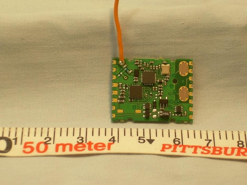
SZV-PTM535U
Sep 17, 2020Temperature and Humidity Sensor with transmitter
Equipment Class
DSC - Part 15 Security/Remote Control Transmitter
SZV-EMDCU
Mar 24, 2020Temperature and Humidity Sensor with transmitter
Equipment Class
DSC - Part 15 Security/Remote Control Transmitter
SZV-PTM215Z
Sep 16, 20132.405GHz - 2.475GHz transmitter
Equipment Class
DXX - Part 15 Low Power Communication Device Transmitter