SZV-STM310CTransmitter Module
EnOcean GmbHApplication Details
- Equipment Class
- DSC - Part 15 Security/Remote Control Transmitter
- Date of Grant
- Sep 26, 2010
- Application Purpose
- Original Equipment
- Date of Application
- Sep 26, 2010
- Equipment Note
- Transmitter Module
- Frequency Range
- 315.00000000 - 315.00000000
- Company
- EnOcean GmbH
- Country
- Germany
Documents & Files
Document Text
Text extracted from the exhibit documents filed with the FCC. Open a document above to read the original.
Users Manual
USER MANUAL V0.6 EnOcean GmbH Kolpingring 18a 82041 Oberhaching Germany Phone +49.89.67 34 689-0 Fax +49.89.67 34 689-50 [email protected] www.enocean.com Subject to modifications STM 31x / STM 31xC User Manual V0.6 September 7, 2010 3:58 PM Page 1/28 Patent protected: WO98/36395, DE 100 25 561, DE 101 50 128, WO 2004/051591, DE 103 01 678 A1, DE 10309334, WO 04/109236, WO 05/096482, WO 02/095707, US 6,747,573, US 7,019,241 Observe precautions! Electrostatic sensitive devices! Scavenger Transmitter Module STM 31x / STM 31xC September 7, 2010 USER MANUAL V0.6 © 2010 EnOcean | www.enocean.comSTM 31x / STM 31xC User Manual V0.6 | Page 2/28 STM 31X / STM 31XC REVISION HISTORY The following major modifications and improvements have been made to the first version of this document: No Major Changes 0.5 Initial version 0.6 New drawings added, Agency approvals added Published by EnOcean GmbH, Kolpingring 18a, 82041 Oberhaching, Germany www.enocean.com, [email protected], phone ++49 (89) 6734 6890 © EnOcean GmbH All Rights Reserved Important! This information describes the type of component and shall not be considered as assured characteris- tics. No responsibility is assumed for possible omissions or inaccuracies. Circuitry and specifications are subject to change without notice. For the latest product specifications, refer to the EnOcean web- site: http://www.enocean.com. As far as patents or other rights of third parties are concerned, liability is only assumed for modules, not for the described applications, processes and circuits. EnOcean does not assume responsibility for use of modules described and limits its liability to the replacement of modules determined to be defective due to workmanship. Devices or systems contain- ing RF components must meet the essential requirements of the local legal authorities. The modules must not be used in any relation with equipment that supports, directly or indirectly, human health or life or with applications that can result in danger for people, animals or real value. Components of the modules are considered and should be disposed of as hazardous waste. Local government regulations are to be observed. Packing: Please use the recycling operators known to you. By agreement we will take packing mate- rial back if it is sorted. You must bear the costs of transport. For packing material that is returned to us unsorted or that we are not obliged to accept, we shall have to invoice you for any costs incurred. USER MANUAL V0.6 © 2010 EnOcean | www.enocean.comSTM 31x / STM 31xC User Manual V0.6 | Page 3/28 STM 31X / STM 31XC TABLE OF CONTENT 1 GENERAL DESCRIPTION................................................................................. 4 1.1 Basic functionality ......................................................................................... 4 1.2 Technical data .............................................................................................. 5 1.3 Physical dimensions....................................................................................... 5 1.4 Environmental conditions ............................................................................... 7 1.5 Ordering Information ..................................................................................... 7 2 FUNCTIONAL DESCRIPTION............................................................................ 8 2.1 Simplified firmware flow chart and block diagram .............................................. 8 2.2 Pin out ......................................................................................................... 9 2.3 Pin description and operational characteristics ................................................ 10 2.3.1 Interface supply voltage........................................................................... 11 2.3.2 Analog and digital inputs .......................................................................... 12 2.4 Absolute maximum ratings (non operating) .................................................... 12 2.5 Maximum ratings (operating)........................................................................ 12 2.6 Power management and voltage regulators .................................................... 13 2.7 Configuration .............................................................................................. 13 2.7.1 Configuration via pins .............................................................................. 13 2.7.2 Configuration via serial interface ............................................................... 15 2.8 Radio telegram ........................................................................................... 16 2.8.1 Normal operation .................................................................................... 16 2.8.2 Teach-in telegram ................................................................................... 17 2.9 Transmit timing .......................................................................................... 17 2.10 Charging circuitry ................................................................................... 18 2.11 Energy consumption ............................................................................... 18 3 APPLICATIONS INFORMATION ...................................................................... 20 3.1 Using the WAKE pins ................................................................................... 20 3.2 Antenna options.......................................................................................... 22 3.2.1 Whip antenna (STM 310, STM 310C, STM 312, STM 312C) ........................... 22 3.2.2 Helical antenna (STM 311, STM 311C) ....................................................... 23 3.3 Transmission range ..................................................................................... 24 4 AGENCY CERTIFICATIONS ............................................................................ 25 4.1 CE Approval........…
Text truncated - open the document above for the full version.
Block Diagram
Block diagram of STM310C / STM312C / STM330C CONFIDENTIAL INFORMATION GND CW_1CW_0 WAKE0 CP_1 CP_0 LED LRN VDD Whip antenna UVDDext RESET BALUN Presence Signal(every 100th,every 10th,every cyclic wake-upor SW defined) Spontaneous wake-upCyclic Wake-up(every 1s ,10s , 100s, or SW defined) A/D Power management MicroController RF Transmitter315.0 MHz Oscillator DOLPHIN EO3000I 16MHz Oscillator SWPWR EnergyStorage VCHAR VGC Solar Cell(not on STM312C) LRN button TransmitIndicatorAD_2AD_1AD_0DI_2DI_1DI_0
Cover Letter(s)
EnOcean GmbH Kolpingring 18a 82041 Oberhaching Germany Phone +49.89.67 34 689-0 Fax +49.89.67 34 689-50 [email protected] www.enocean.com Managing Directors: Markus Brehler, Uwe Thumm Registered Court Munich HRB 139781 VAT Reg.No. DE813355588 Account: HypoVereinsbank München No. 2440610 Bank Code 700 202 70 EnOcean GmbH Kolpingring 18a 82041 Oberhaching/Germany Dr. Wolfgang Heller Product Line Manager Phone +49.89.67 34 689-34 Fax +49.89.67 34 689-55 Mobile +170.855 92 64 [email protected] OEM Agreement Governing use of EnOcean Limited Modular Approval STM310C, STM312C, STM330C This Agreement (the “Agreement ”), is made and entered into as of ________, 2010 (the “Effective Date ”) by and between EnOcean GmbH with its principal place of business located at Kolpingring 18a, D-82041 Oberhaching, Germany (“EnOcean ”), and ____________________________, a _______________ with its principal place of business located at _____________, hereinafter referred to as “PARTY” or “PARTIES” respectively. NOW, THEREFORE, in consideration of the foregoing and of the mutual covenants, promises and agreements contained in the following provisions, and intending to be legally bound by this Agreement, the Parties agree as follows: LIMITED MODULAR APPROVAL EnOcean RF modules, approved for Limited Modular use, operate as intentional transmitting devices with respect to 47 CFR 15.231(a-c) and are limited to OEM installation. The modules are optimized to operate using small amounts of harvested energy, and may be powered by a small solar cell exposed to ambient light or a battery. The module transmits short radio packets comprised of control signals, (in some cases the control signal may be accompanied with data) such as those used with alarm systems, door openers, remote switches, and the like. The module does not support continuous streaming of voice, video, or any other forms of streaming data; it sends only short packets containing control signals and possibly data. The module is designed to comply with, has been tested according to 15.231(a-c), and has been found to comply with each requirement. Thus, a finished device containing an EnOcean radio module can be operated in the United States and Canada without additional FCC/IC approval (approval(s) for unintentional radiators may be required Date: 25 August 2010 Page: 1 EnOcean GmbH Kolpingring 18a 82041 Oberhaching Germany Phone +49.89.67 34 689-0 Fax +49.89.67 34 689-50 [email protected] www.enocean.com Management: Markus Brehler, Uwe Thumm Registered Court Munich HRB 139781 VAT Reg No. DE813355588 Account: HypoVereinsbank München No. 2440610 Bank Code 700 202 70 Date: August 25, 2010 Page: 2 for the OEM’s finished product), under EnOcean’s FCC ID number. This greatly simplifies and shortens the design cycle and development costs for OEM integrators. The module can be triggered manually or automatically, which cases are described below. Manual Activation The radio module can be configured to transmit a short packetized control signal if triggered manually. The module can be triggered by pressing a switch, for example. The packet contains one (or more) control signals that is (are) intended to control something at the receiving end. The packet may also contain data. Depending on how much energy is available from the energy source, subsequent manual triggers can initiate the transmission of additional control signals. This may be necessary if prior packet(s) was (were) lost due to fading or interference. Subsequent triggers can also be initiated as a precaution if any doubt exists that the first packet didn’t arrive at the receiver. Each packet that is transmitted, regardless of whether it was the first one or a subsequent one, will only be transmitted if enough energy is available from the energy source. Automatic Activation The radio module also can be configured to transmit a short packetized control signal if triggered automatically, by a relevant change of its inputs, for example. Again, the packet contains a control signal that is intended to control something at the receiving end and may also contain data. As above, it is possible for the packet to get lost and never reach the receiver. However, if enough energy is available from the energy source, and the module has been configured to do so, then another packet or packets containing the control signal may be transmitted at a later, unpredictable time. (I) FCC requirements: (a) In order to use the FCC/IC grant, the OEM must not operate or configure the module in such a way that the module will transmit more than 2 seconds telegrams per hour. (b) End users of products which contain the module must not have the ability to alter the firmware that governs the operation of the module. The agency grant is valid only when the module is incorporated into a final product by OEM integrators. EnOcean GmbH Kolpingring 18a 82041 Oberhaching Germany Phone +49.89.67 34 689-0 Fax +49.89.67 34 689-50 [email protected] www.enocean.com Management: Markus Brehler, Uwe Thumm Registered Court Munich HRB 139781 VAT Reg No. DE813355588 Account: HypoVereinsbank München No. 2440610 Bank Code 700 202 70 Date: August 25, 2010 Page: 3 (c) The end-user must not be provided with instructions to remove, adjust or install the module. The OEM must instruct the end user not to do so by providing appropriate written documentation (d) FCC labeling requirements: The Original Equipment Manufacturer (OEM) must ensure that FCC labeling requirements are met. This includes a clearly visible label on the outside of the final product. Attaching a label to a removable portion of the final product, such as a battery cover, is not permitted. The label must include the following text: Contains FCC ID: SZV-STM310C The enclosed device complies with Part 15 of the FCC Rules. Operation is subject to the following two conditions: (i.) this device may not cause harmful interference and (ii.) this device must accept any interference received, includin…
Text truncated - open the document above for the full version.
External Photos
External Photos (STM310C / STM312C / STM330C) Top View STM310C, STM312C, STM330C Bottom View STM310C, STM330C STM312C
ID Label/Location Info
ID Label and Label Location (STM310C / STM312C / STM330C) STM310C STM312C STM330C The tradename „EnOcean“ is visible on the other side of the module IC:5713A – STM310C FCC ID:SZV - STM310C STM310C IC:5713A – STM310C FCC ID:SZV - STM310C STM312C IC:5713A – STM310C FCC ID:SZV - STM310C STM330C
Internal Photos
Internal Photos (STM310C / STM312C / STM330C) Top View STM310C, STM312C, STM330C Bottom View STM310C, STM330C STM312C
Operational Description
USER MANUAL V0.6 EnOcean GmbH Kolpingring 18a 82041 Oberhaching Germany Phone +49.89.67 34 689-0 Fax +49.89.67 34 689-50 [email protected] www.enocean.com Subject to modifications STM 31x / STM 31xC User Manual V0.6 September 7, 2010 3:58 PM Page 1/28 Patent protected: WO98/36395, DE 100 25 561, DE 101 50 128, WO 2004/051591, DE 103 01 678 A1, DE 10309334, WO 04/109236, WO 05/096482, WO 02/095707, US 6,747,573, US 7,019,241 Observe precautions! Electrostatic sensitive devices! Scavenger Transmitter Module STM 31x / STM 31xC September 7, 2010 USER MANUAL V0.6 © 2010 EnOcean | www.enocean.comSTM 31x / STM 31xC User Manual V0.6 | Page 2/28 STM 31X / STM 31XC REVISION HISTORY The following major modifications and improvements have been made to the first version of this document: No Major Changes 0.5 Initial version 0.6 New drawings added, Agency approvals added Published by EnOcean GmbH, Kolpingring 18a, 82041 Oberhaching, Germany www.enocean.com, [email protected], phone ++49 (89) 6734 6890 © EnOcean GmbH All Rights Reserved Important! This information describes the type of component and shall not be considered as assured characteris- tics. No responsibility is assumed for possible omissions or inaccuracies. Circuitry and specifications are subject to change without notice. For the latest product specifications, refer to the EnOcean web- site: http://www.enocean.com. As far as patents or other rights of third parties are concerned, liability is only assumed for modules, not for the described applications, processes and circuits. EnOcean does not assume responsibility for use of modules described and limits its liability to the replacement of modules determined to be defective due to workmanship. Devices or systems contain- ing RF components must meet the essential requirements of the local legal authorities. The modules must not be used in any relation with equipment that supports, directly or indirectly, human health or life or with applications that can result in danger for people, animals or real value. Components of the modules are considered and should be disposed of as hazardous waste. Local government regulations are to be observed. Packing: Please use the recycling operators known to you. By agreement we will take packing mate- rial back if it is sorted. You must bear the costs of transport. For packing material that is returned to us unsorted or that we are not obliged to accept, we shall have to invoice you for any costs incurred. USER MANUAL V0.6 © 2010 EnOcean | www.enocean.comSTM 31x / STM 31xC User Manual V0.6 | Page 3/28 STM 31X / STM 31XC TABLE OF CONTENT 1 GENERAL DESCRIPTION................................................................................. 4 1.1 Basic functionality ......................................................................................... 4 1.2 Technical data .............................................................................................. 5 1.3 Physical dimensions....................................................................................... 5 1.4 Environmental conditions ............................................................................... 7 1.5 Ordering Information ..................................................................................... 7 2 FUNCTIONAL DESCRIPTION............................................................................ 8 2.1 Simplified firmware flow chart and block diagram .............................................. 8 2.2 Pin out ......................................................................................................... 9 2.3 Pin description and operational characteristics ................................................ 10 2.3.1 Interface supply voltage........................................................................... 11 2.3.2 Analog and digital inputs .......................................................................... 12 2.4 Absolute maximum ratings (non operating) .................................................... 12 2.5 Maximum ratings (operating)........................................................................ 12 2.6 Power management and voltage regulators .................................................... 13 2.7 Configuration .............................................................................................. 13 2.7.1 Configuration via pins .............................................................................. 13 2.7.2 Configuration via serial interface ............................................................... 15 2.8 Radio telegram ........................................................................................... 16 2.8.1 Normal operation .................................................................................... 16 2.8.2 Teach-in telegram ................................................................................... 17 2.9 Transmit timing .......................................................................................... 17 2.10 Charging circuitry ................................................................................... 18 2.11 Energy consumption ............................................................................... 18 3 APPLICATIONS INFORMATION ...................................................................... 20 3.1 Using the WAKE pins ................................................................................... 20 3.2 Antenna options.......................................................................................... 22 3.2.1 Whip antenna (STM 310, STM 310C, STM 312, STM 312C) ........................... 22 3.2.2 Helical antenna (STM 311, STM 311C) ....................................................... 23 3.3 Transmission range ..................................................................................... 24 4 AGENCY CERTIFICATIONS ............................................................................ 25 4.1 CE Approval........…
Text truncated - open the document above for the full version.
Test Report
This document was signed electronically. The Center for Quality Engineering of SGS Germany GmbH is accredited by DATech for COMPONENTS TESTING ENVIRONMENTAL ENGINEERING ELECTROMAGNETIC COMPATIBILITY PRODUCT SAFETY TELECOM CONFORMANCE TESTS SGS Germany GmbH, SGS CQE, Hofmannstr. 50, D-81379 München, Phone +49 89-787475-130, Fax +49 89-787475-122, Internet www.sgs-cqe.de The test report shall not be reproduced except in full without the written approval of the testing laboratory DAT-PL-002/91-03 Center for Quality Engineering Test Report No.: D15F0001 FCC ID: SZV-STM310C IC: 5713A-STM310C Order No.: D15F Pages: 28 Munich, Sep 24, 2010 Client: EnOcean GmbH Equipment Under Test: Transmitter Module STM310C (Whip antenna, 15cm) Manufacturer: EnOcean GmbH Task: Conformance test according to the test specifications mentioned below Test Specification(s): FCC 47 CFR Part 15 IC RSS-210 Result: The EUT complies with the requirements of the specification. The results relate only to the items tested as described in this test report. edited by: Date Signature Steinmüller Qualification Engineer Sep 24, 2010 approved by: Date Signature Bauer Lab Manager EMC Sep 24, 2010 Test Report No.: D15F0001 Date: Sep 24, 2010 Transmitter Module STM310C (Whip antenna, 15cm) page 2 / 28 The test report shall not be reproduced except in full without the written approval of the testing laboratory CONTENTS 1 Summary ..................................................................................................................................4 2 References ...............................................................................................................................5 2.1 Specifications ......................................................................................................................5 2.2 Glossary of Terms...............................................................................................................5 3 General Information ................................................................................................................6 3.1 Identification of Client..........................................................................................................6 3.2 Test Laboratory ...................................................................................................................6 3.3 Time Schedule ....................................................................................................................6 3.4 Participants .........................................................................................................................6 4 Equipment Under Test ............................................................................................................7 4.1 Description of EUT ..............................................................................................................7 4.2 Configuration of EUT...........................................................................................................8 4.3 Operating Conditions ..........................................................................................................8 4.4 Compliance Criteria.............................................................................................................8 5 General Description of Tests..................................................................................................9 5.1 Tested Carrier Frequencies ................................................................................................9 5.2 Calibration of the Test Equipment.......................................................................................9 6 Test Results ...........................................................................................................................10 6.1 Test No. 1: Conducted Emissions ([1] § 15.207) ..............................................................10 6.2 Test No. 2: Field strength correction for pulse operation (Duty Cycle) ([1] § 15.35(c)) .....10 6.2.1 Purpose ......................................................................................................................10 6.2.2 Limits ..........................................................................................................................10 6.2.3 EUT Operating Condition ...........................................................................................10 6.2.4 Test Configuration ......................................................................................................10 6.2.5 Test Procedure and Results .......................................................................................11 6.2.6 Test Protocol ..............................................................................................................11 6.3 Test No. 3: Field strength of the fundamental wave ([1] § 15.231(b), [3] A1.1.2) .............13 6.3.1 Purpose ......................................................................................................................13 6.3.2 Limits ..........................................................................................................................13 6.3.3 EUT Operating Condition ...........................................................................................13 6.3.4 Test Configuration ......................................................................................................13 6.3.5 Test Procedure and Results .......................................................................................14 6.3.6 Test Protocol ..............................................................................................................14 6.4 Test No. 4: Radiated Emissions (9kHz – 30MHz) ([1] § 15.209; [3] T1, 3) .......................15 6.4.1 Purpose ......................................................................................................................15 Test Report No.: D15F0001 Date: Sep 24, 2010 Tra…
Text truncated - open the document above for the full version.
Test Setup Photos
The Center for Quality Engineering of SGS Germany GmbH is accredited by DATech for COMPONENTS TESTING ENVIRONMENTAL ENGINEERING ELECTROMAGNETIC COMPATIBILITY PRODUCT SAFETY TELECOM CONFORMANCE TESTS SGS Germany GmbH, SGS CQE, Hofmannstr. 50, D-81379 München, Phone +49 89-787475-130, Fax +49 89-787475-122, Internet www.sgs-cqe.de Test Setup Photos - Field strength correction for pulse operation (Duty Cycle) (§ 15.35(c)) and - Emission Bandwidth (§ 15.231(c)) and - Transmit Duration (§ 15.231(a)): 2/3 - Field strength of the fundamental wave (§ 15.231(b)): - Radiated Emissions (9kHz – 30MHz) (§ 15.209): 3/3 - Radiated Emissions (30MHz – 1GHz) (§ 15.209, 231(b)): - Radiated Emissions (1GHz – 4GHz) (§ 15.209, 231(b)):
Contact Information
Applicant
Armin Anders(Director Product Marketing)
Test Firm
SGS Germany GmbHJosef Bauer
Technical Specifications
| # | Rule Parts | Frequency Range | Power Output |
|---|---|---|---|
| 1 | 15.231 | 315 MHz - 315 MHz | - |
Other Applications from EnOcean GmbH

SZV-PTM215U
Feb 04, 2021Temperature and Humidity Sensor with transmitter
Equipment Class
DSC - Part 15 Security/Remote Control Transmitter
SZV-STM550U
Feb 03, 2021Temperature and Humidity Sensor with transmitter
Equipment Class
DSC - Part 15 Security/Remote Control Transmitter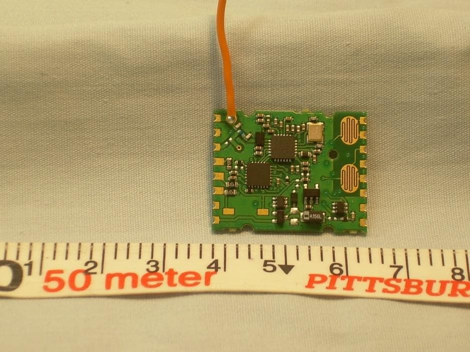
SZV-PTM535U
Sep 17, 2020Temperature and Humidity Sensor with transmitter
Equipment Class
DSC - Part 15 Security/Remote Control Transmitter
SZV-EMDCU
Mar 24, 2020Temperature and Humidity Sensor with transmitter
Equipment Class
DSC - Part 15 Security/Remote Control Transmitter
SZV-PTM215Z
Sep 16, 20132.405GHz - 2.475GHz transmitter
Equipment Class
DXX - Part 15 Low Power Communication Device Transmitter