T2X-V2-CLESS-MRFID Reader
FLOWBIRD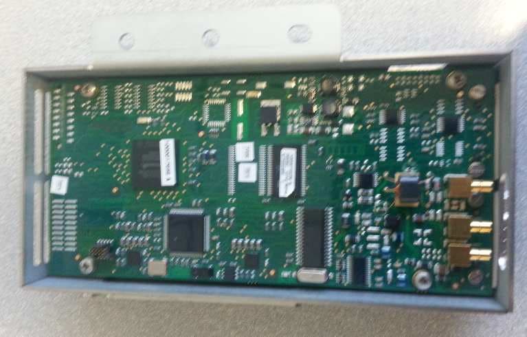
Click to zoom
Application Details
- Equipment Class
- DXX - Part 15 Low Power Communication Device Transmitter
- Date of Grant
- Feb 05, 2014
- Application Purpose
- Original Equipment
- Date of Application
- Feb 05, 2014
- Equipment Note
- RFID Reader
- Frequency Range
- 13.56000000 - 13.56000000
- Company
- FLOWBIRD
- Country
- France
Documents & Files
Document Text
Text extracted from the exhibit documents filed with the FCC. Open a document above to read the original.
Users Manual
V2 CLESS M – USER MANUAL 1 V2 CLESS M User Manual V2 CLESS M – USER MANUAL 2 FOREWORD INSTALLATION. We recommend you to read these instructions very carefully. They are included with your V2 Cless Reader in order to explain its installation. USE. Once it is installed and equipped with the application you case use your V2 Cless reader. GUARANTEE AND SAFETY. In order to benefit from the guarantee on this equipment and in order to follow the safety instructions, only authorized person shall entrust assembly or disassembly procedures and installed the reader. CONTENTS 1. SAFETY INSTRUCTIONS .......................................................................................................................................... 3 2. UNPACKING. PRODUCT CONTENTS...................................................................................................................... 4 3. DESCRIPTION OF THE RF READER ....................................................................................................................... 5 4. INSTALLING THE V2 CLESS .................................................................................................................................... 7 4.1 Module .................................................................................................................................................................. 7 4.2 Antenna................................................................................................................................................................. 8 5. INSTALLING AND REMOVING SECURITY ACCESS MODULES........................................................................... 9 6. DAILY USE .............................................................................................................................................................. 10 7. V2 CLESS CHARACTERISTICS ............................................................................................................................. 11 8. EC STANDARD COMPLIANCE MARKING ............................................................................................................ 12 9. FCC COMPLIANCE STATEMENT........................................................................................................................... 12 V2 CLESS M – USER MANUAL 3 1.SAFETY INSTRUCTIONS A- In order to power down your V2 CLess : Disconnect the V2 Cless power supply block from the electric power supply network B- Electrical power supply a. Only use Parkeon Contacless reader cable b. Only use Parkeon antenna cable with it’s Ferrite for EMI protection c. The V2 Cless input voltage should be +12VDC +/- 10% C- Reader cover Flap The cover flap located on the side ( see chapter – installation and removal of Sams) must be in place during normal operation V2 CLESS M – USER MANUAL 4 2.UNPACKING. PRODUCT CONTENTS Carefully preserve the packaging of the V2 Cless and the antenna. It must be re-used whenever the reader is shipped. V2 CLESS M – USER MANUAL 5 3.DESCRIPTION OF THE RF READER Reminder of Safety Instructions : Select the recommended electrical Power from Excelsys COM0 SWITCH SMB HOST V2 Cless connections COM0 = serial link for debug (option) SMB = RF antenna connection HOST = Serial link + power supply SWITCH = Antenna detection switch (option) V2 CLESS M – USER MANUAL 6 Diagram of connection cess Only 4 different antennas can be integrated ( ref ELM_404304686/ ELM_1000004108 / CAR_10000000081 / CAR_1000006460) Contactless reader cable Power supply and communication of contactless reader with the card connector is made via a cable labeled "CLESS" and "PC" - "POWER CLESS". V2 CLESS M – USER MANUAL 7 Antenna cable The antenna is connected to the contactless reader by means of a cable with an angled MCX coaxial connector and an angled SMB coaxial connector. V2 CLESS M – USER MANUAL 8 4.INSTALLING THE V2 CLESS 4.1 Module Tools required: Philips head screwdriver Time required for the intervention: 2 min Other components to remove/Preliminaries: switch off the power to the devices in EMS mode or with the button on the front of the CPU. Disconnect the antenna cable and the contactless reader cable. Slightly unscrew the two fastening screws with a Philips head screwdriver. Unscrew the two bolts holding the drive module. Antenna cable Fixing screws X2 Contactless reader cable Contactless reader Remove the faulty drive module housing. Mount the new drive module with SAMs (if present in the former). Connect the cables on the previous drive module. Press the power button device of the CPU. Perform a functional test using the "test connection map" from the menu EMS "travel card reader. V2 CLESS M – USER MANUAL 9 4.2 Antenna Connect the antenna cable. Put it on the four screws. V2 CLESS M – USER MANUAL 1 0 5.INSTALLING AND REMOVING SECURITY ACCESS MODULES Tools required: key 8 Time required for the intervention: 8 + 3 min Unscrew the screw that locks the access trap SAMs. Rotate the trap to access locations of SAMs. Locking Screw SAMs slot Contactless reader Access trap SAMs Remove the SAMs their modules. Set new in empty slot positions. Replace the contactless reader. Connect the cables on the previous contactless reader. Press the power button device of the CPU. Perform a functional test using the "test connection map" from the menu EMS "travel card reader. V2 CLESS – USER MANUAL 10 10 6. DAILY USE No specific care shall be done. Clean the antenna each year with Isopropanol V2 CLESS – USER MANUAL 11 11 7. V2 CLESS CHARACTERISTICS Physical Characteristics Mass : approximately 400g without cable Dimensions : approximately 166x79x35 mm (LxW xH) Standards See “EC standard compliance marking” in appendix Operating conditions Class II equipement Electric supply network : 12VDC +/- 10% Max. consumption : 0.5 A Ambiant temperature : from -25°C to +70°C Max. relative humidity : 95% at +55°C Serial link : COM, level RS232 Storage conditions Storage temperature : -20°C, +85°C Max …
Text truncated - open the document above for the full version.
External Photos
V2 CLESS M - External Views 1 V2 CLESS M Pictures of equipment External views V2 CLESS M - External Views 2 © Copyright 2010 Parkeon. All rights reserved. Parkeon reserves all proprietary rights relating to the contents of this document.Parkeon Reserves all rights over usage, reproduction, representation, marketing, translation, adaptation Or modification, and generally all rights over present and future utilisation by any means, for any Purpose and in any territory, throughout the period of protection. All use of the contents of this Document requires the prior written permission of Parkeon. Parkeon reserves the right to change data, drawings and descriptions without prior notice. Certain characteristics may vary according to customer requirements and do not represent a commitment by Parkeon. Parkeon UK Ltd. Membrain House Ferndown Industrial Estate Wimborne, Dorset BH21 7PP – United Kingdown Phone +44 1202 850927 - Fax +44 1202 850903 Parkeon Inc. 40 Twosome Drive, Unit 7 Moorestown NJ 08057 – USA Phone +1 856 234 8000 - Fax +1 856 234 7178 Parkeon S.A.S Parc La Fayette, 6 rue Isaac Newton, 25075 Besançon Cedex 9 - France Phone +33 (0)3 81 54 56 00 – Fax +33 (0)3 81 54 49 96 Head office : 100 avenue de Suffren , 75015 Paris - France Parkeon S.A.S au capital de 30.382.146 euros 444 719 272 R.C.S Paris Printed in France. V2 CLESS M - External Views 3 1. Module Lect V2 CLESS M ( Ref: ELM1000017958) General Views V2 CLESS M - External Views 4 2. Antenne CLESS Dépileur ( Ref: ELM1000004108) General Views 3. Antenne CLESS IMS2 ( Ref: CAR_1000006460) General Views V2 CLESS M - External Views 5 4. Antenne CLESS IML5 ( Ref: CAR_1000000081) general Views 5. Antenne CLESS Cible ( Ref ELM_404304686) General V iews
ID Label/Location Info
T2X-V2-CLESS-M– ID Label Location Information 1 T2X-V2-CLESS-M ID Label / Location Information T2X-V2-CLESS-M– ID Label Location Information 2 © Copyright 2010 Parkeon. All rights reserved. Parkeon reserves all proprietary rights relating to the contents of this document.Parkeon Reserves all rights over usage, reproduction, representation, marketing, translation, adaptation Or modification, and generally all rights over present and future utilisation by any means, for any Purpose and in any territory, throughout the period of protection. All use of the contents of this Document requires the prior written permission of Parkeon. Parkeon reserves the right to change data, drawings and descriptions without prior notice. Certain characteristics may vary according to customer requirements and do not represent a commitment by Parkeon. Parkeon UK Ltd. Membrain House Ferndown Industrial Estate Wimborne, Dorset BH21 7PP – United Kingdown Phone +44 1202 850927 - Fax +44 1202 850903 Parkeon Inc. 40 Twosome Drive, Unit 7 Moorestown NJ 08057 – USA Phone +1 856 234 8000 - Fax +1 856 234 7178 Parkeon S.A.S Parc La Fayette, 6 rue Isaac Newton, 25075 Besançon Cedex 9 - France Phone +33 (0)3 81 54 56 00 – Fax +33 (0)3 81 54 49 96 Head office : 100 avenue de Suffren , 75015 Paris - France Parkeon S.A.S au capital de 30.382.146 euros 444 719 272 R.C.S Paris Printed in France. T2X-V2-CLESS-M– ID Label Location Information 3 1. Location Information Position of the FCC ID 42mm 20 mm IC: 9489A-V2CLESSM FCC ID: T2X-V2-CLESS-M MODEL: ELM1000017958 This device complies with Part 15 of the FCC Rules and Industry Canada licence-exempt RSS standard(s). Operation is subject to the following two conditions: (1) this device may not cause harmful interference, and (2) this device must accept any interference received, including interference that may cause undesired operation. PARKEON T2X-V2-CLESS-M– ID Label Location Information 4 2. . Identification Label : V2 CLESS M ( ELM1000017958) MODEL NUMBER TRADE NAME 2. . Identification Label : Antenne CLESS Dépileur ( Ref: ELM1000004108) T2X-V2-CLESS-M– ID Label Location Information 5 3. . Identification Label : Antenne CLESS IMS2 ( Ref: CAR_1000006460) 4. Identification Label : Antenne CLESS IML5 ( Ref: CAR_1000000081) 5. Identification Label :Antenne CLESS Cible ( Ref ELM_404304686)
ID Label/Location Info
1 T2X-V2-CLESS-M Label V2 CLESS M FCC Label Sample 2 T2X-V2-CLESS-M Label © Copyright 2010 Parkeon. All rights reserved. Parkeon reserves all proprietary rights relating to the contents of this document.Parkeon Reserves all rights over usage, reproduction, representation, marketing, translation, adaptation Or modification, and generally all rights over present and future utilisation by any means, for any Purpose and in any territory, throughout the period of protection. All use of the contents of this Document requires the prior written permission of Parkeon. Parkeon reserves the right to change data, drawings and descriptions without prior notice. Certain characteristics may vary according to customer requirements and do not represent a commitment by Parkeon. Parkeon UK Ltd. Membrain House Ferndown Industrial Estate Wimborne, Dorset BH21 7PP – United Kingdown Phone +44 1202 850927 - Fax +44 1202 850903 Parkeon Inc. 40 Twosome Drive, Unit 7 Moorestown NJ 08057 – USA Phone +1 856 234 8000 - Fax +1 856 234 7178 Parkeon S.A.S Parc La Fayette, 6 rue Isaac Newton, 25075 Besançon Cedex 9 - France Phone +33 (0)3 81 54 56 00 – Fax +33 (0)3 81 54 49 96 Head office : 100 avenue de Suffren , 75015 Paris - France Parkeon S.A.S au capital de 30.382.146 euros 444 719 272 R.C.S Paris Printed in France 3 T2X-V2-CLESS-M Label 42mm 20 mm IC: 9489A-V2CLESSM FCC ID: T2X-V2-CLESS-M MODEL: ELM1000017958 This device complies with Part 15 of the FCC Rules and Industry Canada licence-exempt RSS standard(s). Operation is subject to the following two conditions: (1) this device may not cause harmful interference, and (2) this device must accept any interference received, including interference that may cause undesired operation. PARKEON .
Internal Photos
V2 CLESS M - Internal Views 1 V2 CLESS M Pictures of equipment Internal views V2 CLESS M - Internal Views 2 © Copyright 2010 Parkeon. All rights reserved. Parkeon reserves all proprietary rights relating to the contents of this document.Parkeon Reserves all rights over usage, reproduction, representation, marketing, translation, adaptation Or modification, and generally all rights over present and future utilisation by any means, for any Purpose and in any territory, throughout the period of protection. All use of the contents of this Document requires the prior written permission of Parkeon. Parkeon reserves the right to change data, drawings and descriptions without prior notice. Certain characteristics may vary according to customer requirements and do not represent a commitment by Parkeon. Parkeon UK Ltd. Membrain House Ferndown Industrial Estate Wimborne, Dorset BH21 7PP – United Kingdown Phone +44 1202 850927 - Fax +44 1202 850903 Parkeon Inc. 40 Twosome Drive, Unit 7 Moorestown NJ 08057 – USA Phone +1 856 234 8000 - Fax +1 856 234 7178 Parkeon S.A.S Parc La Fayette, 6 rue Isaac Newton, 25075 Besançon Cedex 9 - France Phone +33 (0)3 81 54 56 00 – Fax +33 (0)3 81 54 49 96 Head office : 100 avenue de Suffren , 75015 Paris - France Parkeon S.A.S au capital de 30.382.146 euros 444 719 272 R.C.S Paris Printed in France. V2 CLESS M - Internal Views 3 1. Module Lect V2 CLESS M ( Ref: ELM1000017958) V2 CLESS M - Internal Views 4 2. Antenne CLESS Dépileur ( Ref: ELM1000004108) 3. Antenne CLESS IMS2 ( Ref: CAR_1000006460) 4. Antenne CLESS IML5 ( Ref: CAR_1000000081) V2 CLESS M - Internal Views 5 5. Antenne CLESS Cible ( Ref ELM_404304686)
Test Report
Siège Social : Emitech ‐ 3, rue des Coudriers ‐ Z.A. de l’Observatoire ‐78180 MONTIGNY LE BX ‐France Siret : 344 545 645 00022 ‐ Tél. : 33 (0)1 30 57 55 55 ‐ Fax : 33 (0)1 30 43 74 48 ‐ E‐mail : [email protected] ‐ URL : www.emitech.fr S.A. au capital de 1 560 000 € ‐ R.C.S. VERSAILLES 344 545 645 ‐ APE 7112B RR051-13-105485-2-A Ed. 0 RADIO test report According to the standard: CFR 47, FCC Part 15 Equipment under test: C Less V2 mifare FCC ID: T2X-V2-CLESS-M Company: PARKEON DISTRIBUTION: Mr BARRAUX (Company: PARKEON) Number of pages: 39 with 7 appendixes Technical Verification and Ed. Date Modified Written by Quality Approval pages Name Visa Name Visa 0 12-NOV-2013 Creation T. LEDRESSEUR Duplication of this test report is only permitted for an integral photographic facsimile. It includes the number of pages referenced here above. This document is the result of testing a specimen or a sample of the product submitted. It does not imply an assessment of the conformity of the whole manufactured products of the tested sample. RR051-13-105485-2-A Ed. 0 Page 2 out of 39 DESIGNATION OF PRODUCT: C Less V2 mifare Serial number (S/N): S 020K 300135 B Reference / model (P/N): ELM1000017958 MANUFACTURER: PARKEON COMPANY SUBMITTING THE PRODUCT: Company: PARKEON Address: PARC LAFAYETTE 6 RUE ISAAC NEWTON 25075 BESANCON CEDEX 9 FRANCE Responsible: Mr Barraux Person present during the tests: Mr Barraux DATES OF TEST: 29-OCT-2013; 30-OCT-2013; 31-OCT-2013; 07-NOV-2013 TESTING LOCATION: EMITECH ANGERS laboratory at JUIGNE SUR LOIRE (49) FRANCE EMITECH ANGERS open area test site in JUIGNE SUR LOIRE (49) FRANCE FCC 2.948 Listed Site Registration Number: 90469 21 rue de la Fuye 49610 Juigne sur Loire France TESTED BY: T. LEDRESSEUR RR051-13-105485-2-A Ed. 0 Page 3 out of 39 CONTENTS TITLE PAGE 1. INTRODUCTION _____________________________________________________________ 4 2. PRODUCT DESCRIPTION ______________________________________________________ 4 3. NORMATIVE REFERENCE ______________________________________________________ 4 4. TEST METHODOLOGY ________________________________________________________ 5 5. TEST EQUIPMENT CALIBRATION DATES __________________________________________ 5 6. TESTS RESULTS SUMMARY ____________________________________________________ 6 7. RADIATED EMISSION LIMITS ___________________________________________________ 9 8. ADDITIONAL PROVISIONS TO THE GENERAL RADIATED EMISSION LIMITATIONS ________ 11 9. OPERATION WITHIN THE BAND 13.110 – 14.010 MHz _____________________________ 13 10. FIELD STRENGTH OUTSIDE THE BAND 13.110‐14.010 MHZ __________________________ 18 APPENDIX 1: Photos of the equipment under test APPENDIX 2: Test set up APPENDIX 3: Test equipment list APPENDIX 4: 6 dB bandwidth APPENDIX 5: 20 dB bandwidth APPENDIX 6: band edge APPENDIX 7: spectrum mask RR051-13-105485-2-A Ed. 0 Page 4 out of 39 1. INTRODUCTION This report presents the results of radio test carried out on the following equipment: C Less V2 mifare, in accordance with normative reference. 2. PRODUCT DESCRIPTION ITU Emission code: 681HD0D Class: B (residential environment) Utilization: reader Antenna type: 4 antennas can be used: - IML5 antenna - IMS antenna - Depileur antenna - Target antenna Operating frequency range: band from 13.110 MHz to 14.010 MHz Number of channels: 1 Channel spacing: not concerned Frequency generation: Quartz Modulation: 2 modulation are used (A and B) Power source: 12 Vd.c. Power level, frequency range and channels characteristics are not user adjustable. The details pictures of the product and the circuit boards are joined with this file. 3. NORMATIVE REFERENCE The standards and testing methods related throughout this report are those listed below. They are applied on the whole test report even though the extensions (version, date and amendment) are not repeated. CFR 47 FCC Part 15 (2013) Radio Frequency Devices ANSI C63.4 (2003) Methods of Measurement of Radio-Noise Emissions from Low voltage Electrical and Electronics Equipment in the range of 9 kHz to 40 GHz. RR051-13-105485-2-A Ed. 0 Page 5 out of 39 4. TEST METHODOLOGY Radio performance tests procedures given in CFR 47 part 15: Subpart B –Unintentional Radiators Paragraph 109: Radiated emission limits Paragraph 111: Antenna power conduction limits for receivers Subpart C – Intentional Radiators Paragraph 203: Antenna requirement Paragraph 205: Restricted bands of operation Paragraph 209: Radiated emission limits; general requirements Paragraph 212: Modular transmitter Paragraph 215: Additional provisions to the general radiated emission limitations Paragraph 225: Operation within the band 13.110-14.010 MHz 5. TEST EQUIPMENT CALIBRATION DATES Equipment Model Type Last verification Next verification Validity 1211 HP 8901B Modulation analyzer 03/05/2013 03/05/2015 03/07/2015 2593 MPC B25250 Climatic chamber 07/08/2012 07/08/2014 07/10/2014 4088 R&S FSP40 Spectrum analyzer 22/08/2013 22/08/2015 22/10/2015 4195 HP E3610A Power source / / * 7001 R&S FSBS Spectrum analyzer 04/12/2012 04/12/2014 04/02/2015 8511 HP 8447D Low noise preamplifier 22/08/2013 22/08/2014 22/10/2014 8526 Schwarzbeck VHBB 9124 Biconical antenna 12/06/2012 12/06/2016 12/08/2016 8528 Schwarzbeck VHA 9103 Biconical antenna 24/09/2013 24/09/2017 24/11/2017 8533 R&S HFH2-Z2 Loop antenna 01/05/2012 01/05/2014 01/07/2014 8543 Schwarzbeck UHALP 9108A Log periodic antenna 12/06/2012 12/06/2016 12/08/2016 8593 SIDT Cage 2 Full anechoic room / / / 8675 AOIP MN5102B Multimeter 15/01/2013 15/01/2015 15/03/2015 8707 R&S ESI7 Test receiver 03/10/2012 03/10/2014 03/12/2014 8732 Emitech OATS 23/08/2013 23/08/2016 23/10/2016 8749 La Crosse Technology WS- 9232 Meteo station 20/07/2012 20/07/2014 20/09/2014 8750 La Crosse Technology WS- 9232 Meteo station 20/07/2012 20/07/2014 20/09/2014 8896 ACQUISYS GPS8 GPS receiver / / / * The equipment is not verified; instead, the output voltage is checked before each measurement with the calibrated multimeter. RR051-13-105485-…
Text truncated - open the document above for the full version.
Test Setup Photos
Anechoic room Open area test site
Contact Information
Applicant
Eric Epenoy(R&D Engineer)
Test Firm
EMITECH ANGERSOlivier ROY
Technical Specifications
| # | Rule Parts | Frequency Range | Power Output |
|---|---|---|---|
| 1 | 15C | 13.56 MHz - 13.56 MHz | - |
Other Applications from FLOWBIRD

T2X-V3-CLESS
Apr 04, 2023contactless system of validation, payment or identification
Equipment Class
DXX - Part 15 Low Power Communication Device Transmitter
T2X-V2-CLESS
Mar 24, 2011RFID READER
Equipment Class
DXX - Part 15 Low Power Communication Device Transmitter
T2XSTRADA-RAPIDE
Jun 03, 2007PAY & PLAY MACHINE WITH WI-FI
Equipment Class
DTS - Digital Transmission System