T4PPHC8000200701Bluetooth car kit
Caron Autosound Ltd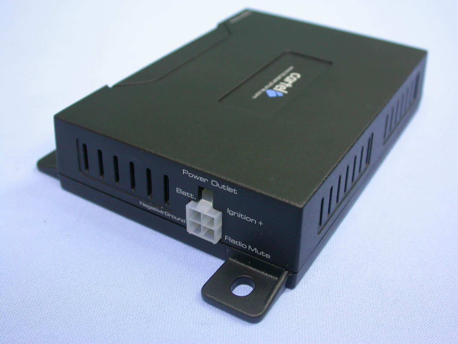
Click to zoom
Application Details
- Equipment Class
- DSS - Part 15 Spread Spectrum Transmitter
- Date of Grant
- Sep 29, 2007
- Application Purpose
- Original Equipment
- Date of Application
- Sep 29, 2007
- Equipment Note
- Bluetooth car kit
- Frequency Range
- 2402.00000000 - 2480.00000000
- Company
- Caron Autosound Ltd
- Country
- Hong Kong
Documents & Files
Document Text
Text extracted from the exhibit documents filed with the FCC. Open a document above to read the original.
Attestation Statements
Bluetooth Declaration Per FCC 15.247 Requirements 1 Output power and channel separation of a Bluetooth device in the different operating modes: The different operating modes (data-mode, acquisition-mode) of a Bluetooth device don’t influence the output power and the channel spacing. There is only one transmitter which is driven by identical input parameters concerning these two parameters. Only a different hopping sequence will be used. For this reason the check of these RF parameters in one op-mode is sufficient. 2 Frequency range of a Bluetooth device: Hereby we declare that the maximum frequency of this device is: 2402 – 2480 MHz. This is according the Bluetooth Core Specification V 1.0B (+ critical errata) for devices which will be operated in the USA. This was checked during the Bluetooth Qualification tests (Test Case: TRM/CA/04-E). Other frequency ranges ( e.g. for Spain, France, Japan) which are allowed according the Core Specification are not supported by this device. 3 Co-ordination of the hopping sequence in data mode to avoid simultaneous occupancy by multiple transmitters: Bluetooth units which want to communicate with other units must be organized in a structure called piconet. This piconet consist of max. 8 Bluetooth units. One unit is the master the other seven are the slaves. The master co-ordinates frequency occupation in this piconet for all units. As the master hop sequence is derived from it’s BD address which is unique for every Bluetooth device, additional masters intending to establish new piconets will always use different hop sequences. 4 Example of a hopping sequence in data mode: Example of a 79 hopping sequence in data mode: 40, 21, 44, 23, 42, 53, 46, 55, 48, 33, 52, 35, 50, 65, 54, 67, 56, 37, 60, 39, 58, 69, 62, 71, 64, 25, 68, 27, 66, 57, 70, 59, 72, 29, 76, 31, 74, 61, 78, 63, 01, 41, 05, 43, 03, 73, 07, 75, 09, 45, 13, 47, 11, 77, 15, 00, 64, 49, 66, 53, 68, 02, 70, 06, 01, 51, 03, 55, 05, 04 5 Equally average use of frequencies in data mode and behaviour for short transmissions: The generation of the hopping sequence in connection mode depends essentially on two input values: 1. LAP/UAP of the master of the connection 2. Internal master clock The LAP (lower address part) are the 24 LSB’s of the 48 BD_ADDRESS. The BD_ADDRESS is an unambiguous number of every Bluetooth unit. The UAP (upper address part) are the 24 MSB’s of the 48 BD_ADDRESS. The internal clock of a Bluetooth unit is derived from a free running clock which is never adjusted and is never turned off. For synchronisation with other units only offset are used. It has no relation to the time of the day. Its resolution is at least half the RX/TX slot length of 312.5 μs. The clock has a cycle of about one day (23h30). In most case it is implemented as 28 bit counter. For the deriving of the hopping sequence the entire LAP (24 bits), 4 LSB’s (4 bits) (Input 1) and the 27 MSB’s of the clock (Input 2) are used. With this input values different mathematical procedures (permutations, additions, XOR-operations) are performed to generate the sequence. This will be done at the beginning of every new transmission. Regarding short transmissions the Bluetooth system has the following behaviors: The first connection between the two devices is established, a hopping sequence was generated. For transmitting the wanted data the complete hopping sequence was not used. The connection ended. The second connection will be established. A new hopping sequence is generated. Due to the fact that the Bluetooth clock has a different value, because the period between the two transmission is longer (and it cannot be shorter) than the minimum resolution of the clock (312.5 μs). The hopping sequence will always differ from the first one. 6 Receiver input bandwidth and behaviors for repeated single or multiple packets: The input bandwidth of the receiver is 1 MHz. In every connection one Bluetooth device is the master and the other one is the slave. The master determines the hopping sequence (see chapter 5). The slave follows this sequence. Both devices shift between RX and TX time slot according to the clock of the master. Additionally the type of connection (e.g. single or multislot packet) is set up at the beginning of the connection. The master adapts its hopping frequency and its TX/RX timing according to the packet type of the connection. Also the slave of the connection will use these settings. Repeating of a packet has no influence on the hopping sequence. The hopping sequence generated by the master of the connection will be followed in any case. That means, a repeated packet will not be send on the same frequency, it is send on the next frequency of the hopping sequence. 7 Dwell time in data mode The dwell time of 0.3797s within a 30 second period in data mode is independent from the packet type (packet length). The calculation for a 30 second period is a follows: Dwell time = time slot length * hop rate / number of hopping channels *30s Example for a DH1 packet (with a maximum length of one time slot) Dwell time = 625 μs * 1600 1/s / 79 * 30s = 0.3797s (in a 30s period) For multislot packet the hopping is reduced according to the length of the packet. Example for a DH5 packet (with a maximum length of five time slots) Dwell time = 5 * 625 μs * 1600 * 1/5 *1/s / 79 * 30s = 0.3797s (in a 30s period) This is according the Bluetooth Core Specification V 1.0B (+ critical errata) for all Bluetooth devices. There for all Bluetooth devices comply with the FCC dwell time requirement in data mode. This was checked during the Bluetooth Qualification tests. The Dwell time in hybrid mode is measured and stated in the test report. 8 Channel Separation in hybrid mode The nominal channel spacing of the Bluetooth system is 1Mhz independent of the operating mode. The maximum “initial carrier frequency tolerance” which is allowed for Bluetooth is fcenter = 75 kHz. This was checked during the Bluetooth Qualification tests (Test Case:…
Text truncated - open the document above for the full version.
Cover Letter(s)
Dear Lucy, Attached please find the revise User Manual, Cover Letter Bluetooth Declaration Letter and Block Diagram. Any questions please let me know. Thanks. Best regards, Joe ----- Original Message ----- From: Lucy Tsai To: Joe Hsieh Sent: Saturday, September 29, 2007 9:51 AM Subject: RE: Caron Autosound Ltd, FCC ID: T4PPHC8000200701, Assessment NO.: AN07T7229, Notice#1 Hi Joe, Please address following issues. Q#1: Please revise the authorization letter. The format submitted is for IC and other certification. Please be noted that for FCC submission, the authorization letter shall address the requirement of Section 5301 of the Anti-Drug Abuse Act of 1988, 21 U.S.C. for FCC filing. Q#2: Please demonstrate that this Bluetooth device has complied with FCC 15.247 requirement as below: Is the hopping sequence pseudorandom, based on the technical description? Is each channel used equally on average, based on the technical description? Does the associated system receiver have a compliant input bandwidth, based on the measured 20 dB emission bandwidth? Does the associated system receiver have the ability to hop in synchronization with the transmitter, based on the technical description? 15.247(g) Does the design of the frequency hopping system allow it to comply with all pertinent requirements when presented with a lengthy data stream? 15.247(h) Does the frequency hopping system comply with the non-coordination requirement? Q#3: Per 2.1033, a block diagram shall show the frequency of all oscillators in the device. Please include all oscillators into the block diagram. Q#4: Because this is mobile device, so please user manual also need to add following statement for RF exposure requirement. “This equipment complies with FCC RF radiation exposure limits set forth for an uncontrolled environment. This equipment should be installed and operated with a minimum distance of 20 centimeters between the radiato r and your body.” Best Regards Lucy Tsai Technical Review Engineer Compliance Certification Services 47173 Benicia Street Fremont, CA 94538 Direct: (510) 771-1131 Fax: (510) 661-0888 Main: (510) 771-1000 Web Site and TCB Electronic Filing System :http://www.ccsemc.com
External Photos
ETC Report No.: 07-09-MAS-034 Page A1 of A2 FCC ID. :T4PPHC8000200701 ANNEX A: EXTERNAL CONSTRUCTION PHOTOS OF EUT 1. Outside view 1 of EUT 2. Outside view 2 of EUT ETC Report No.: 07-09-MAS-034 Page A2 of A2 FCC ID. :T4PPHC8000200701 3. Outside view 3 of EUT 4. Outside view 4 of EUT
Internal Photos
ETC Report No.: 07-09-MAS-034 Page B1 of B5 FCC ID. :T4PPHC8000200701 ANNEX B: INTERNAL CONSTRUCTION PHOTOS OF EUT 1. Inside View 1 of EUT 2. Inside View 2 of EUT ETC Report No.: 07-09-MAS-034 Page B2 of B5 FCC ID. :T4PPHC8000200701 3. Inside View 3 of EUT 4. Inside View 4 of EUT ETC Report No.: 07-09-MAS-034 Page B3 of B5 FCC ID. :T4PPHC8000200701 5. Front view of PCB1 6. Front view of PCB1 ETC Report No.: 07-09-MAS-034 Page B4 of B5 FCC ID. :T4PPHC8000200701 7. Rear view of PCB1 8. Front view of PCB2 ETC Report No.: 07-09-MAS-034 Page B5 of B5 FCC ID. :T4PPHC8000200701 9. Rear view of PCB2 10. Rear view of PCB2
Test Report
ETC Report No. : 07-09-MAS-034 Sheet 1 of 59 Sheets FCC ID: T4PPHC8000200701 Rev. No 1.0 CONFORMANCE TEST REPORT FOR FCC 47 CFR, Part 15 Subpart C Report No.: 07-09-MAS-034 Client: Caron Autosound Ltd Product: Bluetooth car kit Model: CT-1000 FCC ID: T4PPHC8000200701 Manufacturer/supplier: Grand Union Electronics (Shenzhen ) Company Ltd Date test item received: 2007/08/27 Date test campaign completed: 2007/08/31 Date of issue: 2007/09/17 The test result only corresponds to the tested sample. It is not permitted to copy this report, in part or in full, without the permission of the test laboratory. Total number of pages of this test report: 59 pages Total number of pages of photos: External photos 2 pages Internal photos 5 pages Setup photos 1 pages Test Engineer Checked By Approved By John Li James Joe Hsieh ELECTRONICS TESTING CENTER, TAIWAN NO.8, LANE 29, WENMING RD., LESHAN TSUEN, GUISHAN SHIANG, TAOYUAN COUNTY, TAIWAN 33383, R.O.C.TAIWAN, R.O.C. TEL: (03) 3276170~4 INT: +886-3-3276170~4 FAX: (03) 3276188 INT: +886-3-3276188 ETC Report No. : 07-09-MAS-034 Sheet 2 of 59 Sheets FCC ID: T4PPHC8000200701 Rev. No 1.0 Client : Caron Autosound Ltd Address : Rm 1610-1611, 16/F, Metropole Square, 2 On Yiu Street, Shatin, HK Manufacturer : Grand Union Electronics (Shenzhen ) Company Ltd Address : Zheng Keng Industrial Area, Bantian, Buji Town, Shenzhen City, China EUT : Bluetooth car kit Trade name : Cartel Model No. : CT-1000 Power Source : DC 12V Regulations applied : FCC 47 CFR, Part 15 Subpart C (2006) The testing described in this report has been carried out to the best of our knowledge and ability, and our responsibility is limited to the exercise of reasonable care. This certification is not intended to believe the sellers from their legal and/or contractual obligations. The compliance test is only certified for the test equipment and the results of the testing report relate only to the item tested. The compliance test of this report was conducted in accordance with the appropriate standards. It’s not intention to assure the quality and performance of the product. This report shall not be reproduced except in full, without the approval of ETC. This report must not be used by the client to claim product endorsement by NVLAP or any agency of the U.S. Government. Laboratory Introduction: Electronics Testing Center, Taiwan is recognized, filed and mutual recognition arrangement as following: 1 ISO9001: TüV Product Service 2 ISO/IEC 17025: BSMI, CNLA, DGT, NVLAP, CCIBLAC, UL, Compliance 3 Filing: FCC, Industry Canada, VCCI 4 MRA: Australia, Hong Kong, New Zealand, Singapore, USA, Japan, Korea, China, APLAC through CNLA 5 FCC Registration Number: 90588, 91094, 91095 NVLAP Lab Code 200133-0 ETC Report No. : 07-09-MAS-034 Sheet 3 of 59 Sheets FCC ID: T4PPHC8000200701 Rev. No 1.0 Table of Contents Page 1 GENERAL INFORMATION ................................................................................................................ 5 1.1 Product Description................................................................................................................................ 5 1.2 Characteristics of Device ....................................................................................................................... 5 1.3 Test Methodology .................................................................................................................................. 5 1.4 Modifiction List of EUT ........................................................................................................................ 5 1.5 Test Facility............................................................................................................................................ 5 2 PROVISIONS APPLICABLE............................................................................................................... 6 2.1 Definition ............................................................................................................................................... 6 2.2 Requirement for Compliance ................................................................................................................. 7 2.3 Restricted Bands of Operation ............................................................................................................... 9 2.4 Labeling Requirement ............................................................................................................................ 9 2.5 User Information .................................................................................................................................. 10 3. SYSTEM TEST CONFIGURATION ................................................................................................. 11 3.1 Justification .......................................................................................................................................... 11 3.2 Devices for Tested System ................................................................................................................... 11 4 RADIATED EMISSION MEASUREMENT ..................................................................................... 12 4.1 Applicable Standard ............................................................................................................................. 12 4.2 Measurement Procedure....................................................................................................................... 12 4.3 Measuring Instrument .......................................................................................................................... 14 4.4 Radiated Emission Data ....................................................................................................................... 15 4.5 Field Strength Calculation.................................................................................................................... 22 5 CONDUCTED EMISSION MEASUREMENT...…
Text truncated - open the document above for the full version.
Test Setup Photos
ETC Report No. : 07-09-MAS-034 Sheet 1 of 1 Sheets FCC ID. :T4PPHC8000200701 Photos of Radiation Measuring Setup
Contact Information
Applicant
Marco Lam Wai Choi(marketing manager)
Test Firm
Electronics Testing Center, TaiwanWin-Po Tsai
Technical Specifications
| # | Rule Parts | Frequency Range | Power Output |
|---|---|---|---|
| 1 | 15C | 2.40 GHz - 2.48 GHz | 1.00 mW |
Other Applications from Caron Autosound Ltd
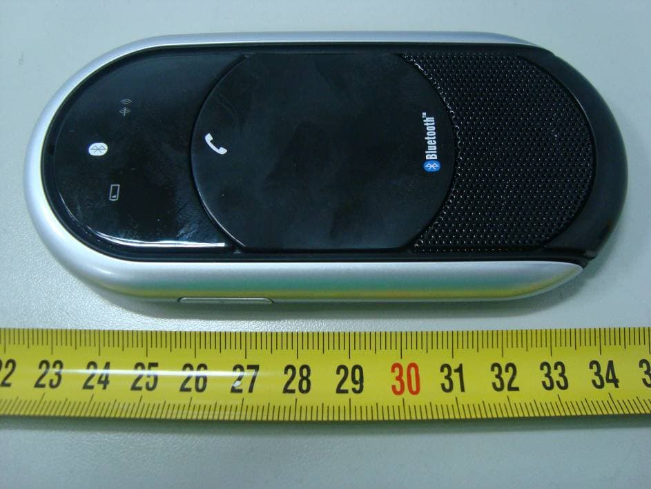
T4P12042010
Jun 17, 2010Bluetooth Speakerphone
Equipment Class
DSS - Part 15 Spread Spectrum Transmitter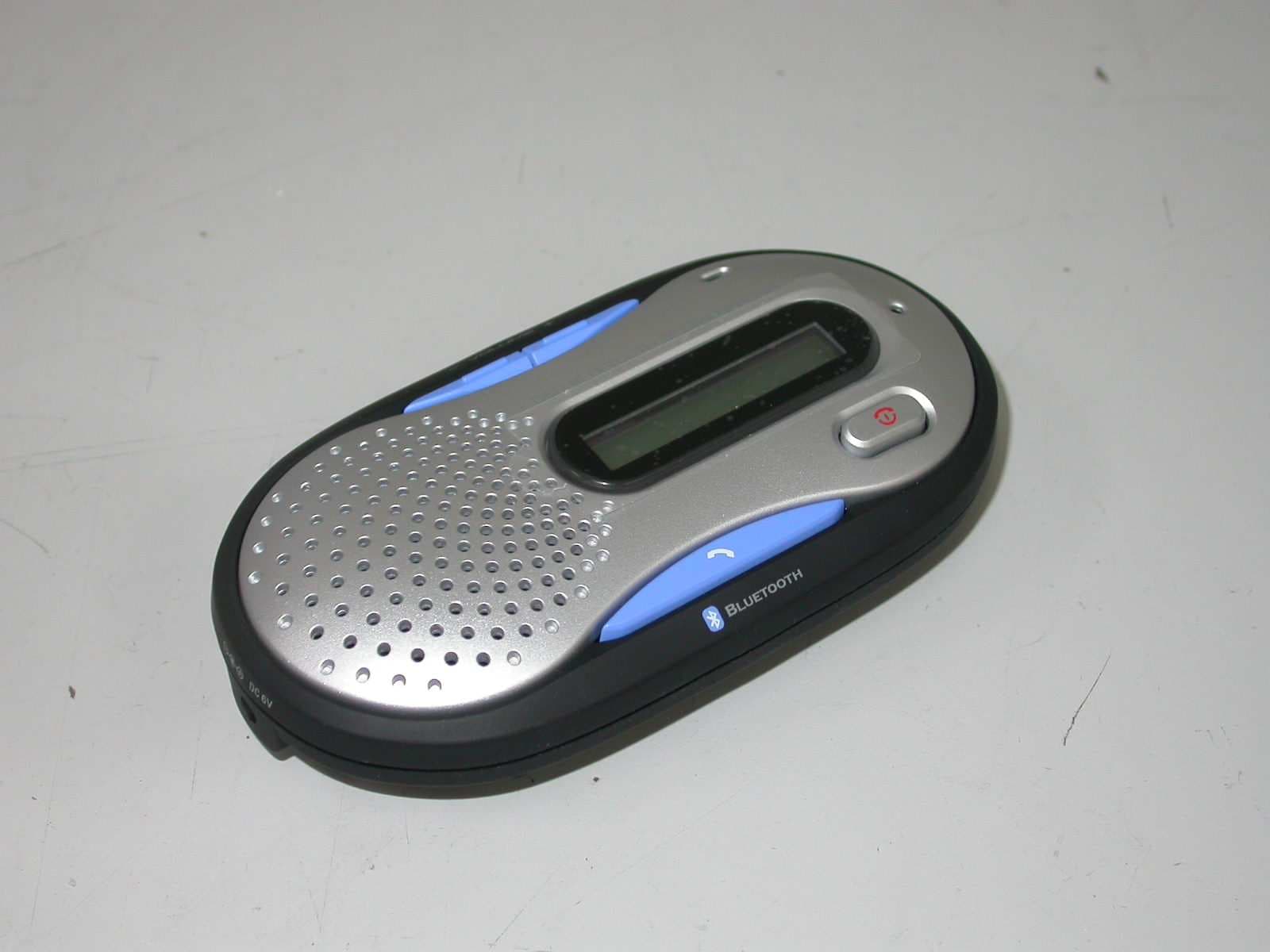
T4PBT180020061010
Nov 19, 2006Bluetooth Car Kit
Equipment Class
DSS - Part 15 Spread Spectrum Transmitter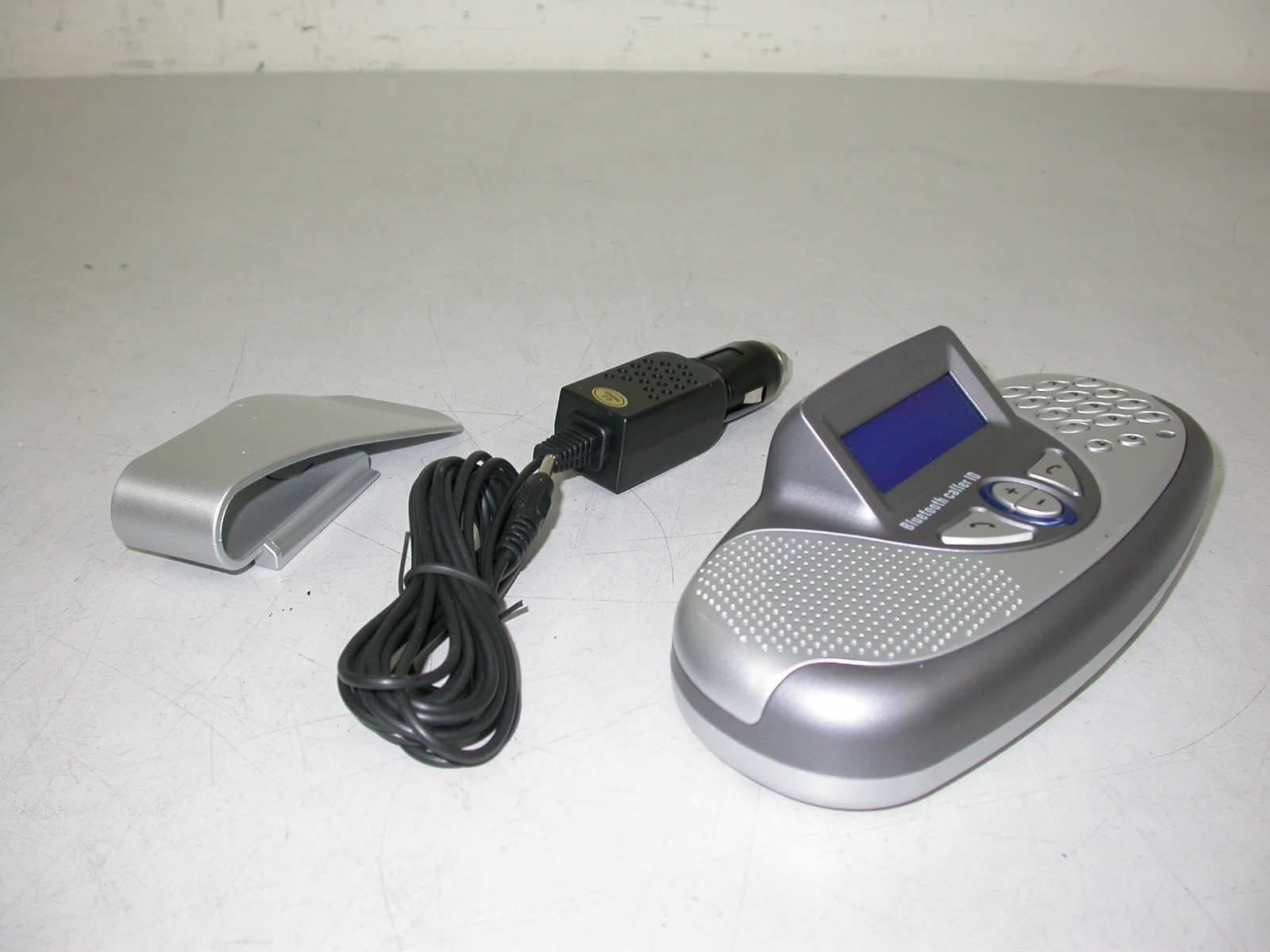
T4PBT200020060101
May 21, 2006Bluetooth Car Kit
Equipment Class
DSS - Part 15 Spread Spectrum Transmitter
T4PBT900D20060101
Mar 29, 2006Bluetooth Car Kit
Equipment Class
DSS - Part 15 Spread Spectrum Transmitter