T7B-4RSuperheterodyne Receiver
EnTire Solutions, LLC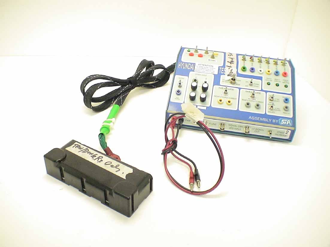
Click to zoom
Application Details
- Equipment Class
- CYY - Communications Receiver used w/Pt 15 Transmitter
- Date of Grant
- Mar 29, 2007
- Application Purpose
- Original Equipment
- Date of Application
- Mar 28, 2007
- Equipment Note
- Superheterodyne Receiver
- Frequency Range
- 315.00000000 - 315.00000000
- Company
- EnTire Solutions, LLC
- Country
- United States
Documents & Files
Document Text
Text extracted from the exhibit documents filed with the FCC. Open a document above to read the original.
Users Manual
EnTire Solutions, LLC 24175 Research Drive Farmington Hills, Mi 48335 FR – Letterhead 03/06 RE: Certification for EnTire Solutions, LLC TPM MY05 Lowline Receiver Model #: 218695-102 FCC ID: T7B-4R Canada IC: 6484A-4R COMPLIANCE STATEMENT The compliance statement for the TPM Receiver (FCC ID: T7B-4R; IC6484A-4R) is integrated into the receiver housing and states as follows: This device complies with part 15 of the FCC rules and with RS-210 of Industry Canada. Operation is subject to the following two conditions: 1. This device may not cause harmful interference, and 2. This device must accept any interference received, including interference that may cause undesired operation. WARNING: Changes or modifications not expressively approved by EnTire Solutions, LLC could void the user’s authority to operate the equipment. The term "IC:" before the radio certification number only signifies that Industry Canada technical specifications were met.
Attestation Statements
Re: Certification for EnTire Receiver Model(s): 218695-102 FCC ID: T7B-4R IC: 6484A-4R POWER OF ATTORNEY A letter granting Valdis V. Liepa the Power of Attorney is on file and can be provided when so requested. Re: Certification for EnTire Receiver Model(s): 218695-102 FCC ID: T7B-4R IC: 6484A-4R REQUEST FOR CONFIDENTIALITY Pursuant to 47 CRF 0.459, EnTire requests that a part of the subject application be held confidential. This comprises Exhibits (5) Schematics (10) Parts List (Part of Exhibit only) EnTire has spent substantial effort in developing this product and it is one of the first of its kind in industry. Having the subject information easily available to "competition" would negate the advantage they have achieved by developing this product. Not protecting the details of the design will result in financial hardship. If there are any questions regarding this request, please contact me at the above address or call 734-483-4211, fax 734-647-2106 or e-mail [email protected]. Sincerely, Valdis V. Liepa Research Scientist University of Michigan March 27, 2007 Re: Certification for EnTire Receiver Model(s): 218695-102 FCC ID: T7B-4R IC: 6484A-4R STATEMENT OF MODIFICATIONS There were no modifications made to the DUT by this test laboratory. (Also see Section 3.1 of the attached Test Report). _____________________ Valdis V. Liepa Research Scientist Re: Certification for EnTire Receiver Model(s): 218695-102 FCC ID: T7B-4R IC: 6484A-4R GENERAL PRODUCT INFORMATION The device, for which certification is pursued, has been designed by: EnTire Solutions, LLC 24175 Research Drive Farmington Hills, MI 48335-2642 Timothy Regnerus Tel: (248) 426-3999 Fax: (248) 478-7241 It will be manufactured by: TRW Automotive Electronics 2240 Cranbrook Drive Auburn, NY 13021 Timothy Regnerus Tel: (248) 426-3999 Fax: (248) 478-7241 Canadian Contact: TRW Canada Limited 16643 Highway 12 Midland, Ontario, Canada L4R4L5 Phone Number: 705.526.8791 FAX: 705.527.6232 Contact: Bob Millett ext 4103
Block Diagram
EnTire Solutions, LLC 24175 Research Drive Farmington Hills, Mi 48335 FR – Letterhead 03/06 RE: Certification for EnTire Solutions, LLC TPM MY05 Lowline Receiver Model #: 218695-102 FCC ID: T7B-4R Canada IC: 6484A-4R BLOCK DIAGRAM Figure 3. TPM Lowline Receiver Block Diagram 651.4 MHz VCO (2 x LO)
ID Label/Location Info
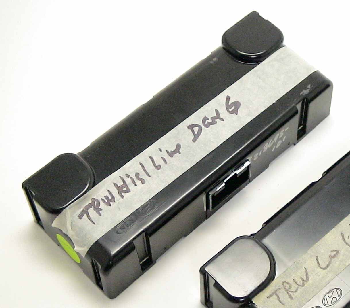
T7B-4R 6484A-4R 218695-102
Operational Description
EnTire Solutions, LLC 24175 Research Drive Farmington Hills, Mi 48335 FR – Letterhead 03/06 RE: Certification for EnTire Solutions, LLC TPM MY05 Lowline Receiver Model #: 218695-102 FCC ID: T7B-4R Canada IC: 6484A-4R GENERAL DESCRIPTION The TPM Lowline receiver is used to monitor RF transmissions from the TPM wheel sensors. The TPM wheel speed sensors transmit information continuously to the receiver on a periodic basis. The transmissions contain information on the pressure and temperature of each of the vehicle’s tires, which is used to signal low inflation warnings to the driver. The signaling is done via dashboard lamps which indicate a low inflation state for any of the tires. The receiver also monitors the performance of the components in the TPM system and will signal a fault to the driver if the performance of the system is compromised.
Test Report
University of Michigan Radiation Laboratory FCC Part 15, IC RSS-210/Gen - Test Report No. 415031-360 Page 1 of 9 The University of Michigan Radiation Laboratory 3228 EECS Building Ann Arbor, MI 48109-2122 Tel: (734) 764-0500 Measured Radio Frequency Emissions From EnTire Solutions, LLC Superheterodyne Receiver Model(s): 218695-102 Report No. 415031-360 March 23, 2007 Copyright © 2007 For: EnTire Solutions, LLC 24175 Research Drive Farmington Hills, MI 48335-2642 Contact: David Glidden [email protected] Tel: (248) 442-5271 Fax: (248) 478-7241 PO: Verbal Tests supervised by: Measurements made by: Valdis V. Liepa Report approved by: _____________________ Valdis V. Liepa Test Report Prepared by: Joseph D. Brunett Research Scientist Summary Tests for compliance with FCC Regulations Part 15, Subpart B, and Industry Canada RSS-210/GEN, were performed on EnTire Solutions, LLC model 218695-102. This device is subject to the Rules and Regulations as a Receiver. As a Digital Device it is exempt, but such measurements were made to assess the receiver's overall emissions. In testing completed on February 9, 2007, the device tested in the worst case met the allowed Class B specifications for radiated emissions by 14.2 dB (see p. 6). The conducted emissions tests do not apply, since the device is powered from a 12 VDC system. University of Michigan Radiation Laboratory FCC Part 15, IC RSS-210/Gen - Test Report No. 415031-360 Page 2 of 9 1. Introduction EnTire Solutions, LLC model 218695-102 was tested for compliance with FCC Regulations, Part 15, adopted under Docket 87-389, April 18, 1989 as subsequently amended, and with Industry Canada RSS- 210, Issue 6 and RSS-Gen, Issue 1, September, 2005. The tests were performed at the University of Michigan Radiation Laboratory Willow Run Test Range following the procedures described in ANSI C63.4-2003 "Methods of Measurement of Radio-Noise Emissions from Low-Voltage Electrical and Electronic Equipment in the Range of 9 kHz to 40 GHz". The Site description and attenuation characteristics of the Open Site facility are on file with FCC Laboratory, Columbia, Maryland (FCC Reg. No: 91050) and with Industry Canada, Ottawa, ON (File Ref. No: IC 2057). 2. Test Procedure and Equipment Used The pertinent test equipment commonly used in our facility for measurements is listed in Table 2.1 below. The middle column identifies the specific equipment used in these tests. Table 2.1 Test Equipment. Test Instrument Eqpt. Used Manufacturer/Model Spectrum Analyzer (0.1-1500 MHz) Hewlett-Packard, 182T/8558B Spectrum Analyzer (9kHz-22GHz) X Hewlett-Packard 8593A SN: 3107A01358 Spectrum Analyzer (9kHz-26GHz) X Hewlett-Packard 8593E, SN: 3412A01131 Spectrum Analyzer (9kHz-26GHz) Hewlett-Packard 8563E, SN: 3310A01174 Spectrum Analyzer (9kHz-40GHz) Hewlett-Packard 8564E, SN: 3745A01031 Power Meter Hewlett-Packard, 432A Power Meter Anritsu, ML4803A/MP Harmonic Mixer (26-40 GHz) Hewlett-Packard 11970A, SN: 3003A08327 Harmonic Mixer (40-60 GHz) Hewlett-Packard 11970U, SN: 2332A00500 Harmonic Mixer (75-110 GHz) Hewlett-Packard 11970W, SN: 2521A00179 Harmonic Mixer (140-220 GHz) Pacific Millimeter Prod., GMA, SN: 26 S-Band Std. Gain Horn S/A, Model SGH-2.6 C-Band Std. Gain Horn University of Michigan, NRL design XN-Band Std. Gain Horn University of Michigan, NRL design X-Band Std. Gain Horn S/A, Model 12-8.2 X-band horn (8.2- 12.4 GHz) Narda 640 X-band horn (8.2- 12.4 GHz) Scientific Atlanta , 12-8.2, SN: 730 K-band horn (18-26.5 GHz) FXR, Inc., K638KF Ka-band horn (26.5-40 GHz) FXR, Inc., U638A U-band horn (40-60 GHz) Custom Microwave, HO19 W-band horn(75-110 GHz) Custom Microwave, HO10 G-band horn (140-220 GHz) Custom Microwave, HO5R Bicone Antenna (30-250 MHz) X University of Michigan, RLBC-1 Bicone Antenna (200-1000 MHz) X University of Michigan, RLBC-2 Dipole Antenna Set (30-1000 MHz) X University of Michigan, RLDP-1,-2,-3 Dipole Antenna Set (30-1000 MHz) EMCO 2131C, SN: 992 Active Rod Antenna (30 Hz-50 MHz) EMCO 3301B, SN: 3223 Active Loop Antenna (30 Hz-50 MHz) EMCO 6502, SN:2855 Ridge-horn Antenna (300-5000 MHz) X University of Michigan Amplifier (5-1000 MHz) X Avantak, A11-1, A25-1S Amplifier (5-4500 MHz) X Avantak Amplifier (4.5-13 GHz) Avantek, AFT-12665 Amplifier (6-16 GHz) Trek Amplifier (16-26 GHz) Avantek LISN Box University of Michigan Signal Generator X Hewlett-Packard 8657B University of Michigan Radiation Laboratory FCC Part 15, IC RSS-210/Gen - Test Report No. 415031-360 Page 3 of 9 3. Configuration and Identification of Device Under Test 3.1 Design and Identification of the Device The DUT was designed by EnTire Solutions, LLC, 24175 Research Drive, Farmington Hills, MI 48335- 2642. It is identified as: EnTire Solutions, LLC Receiver Model(s): 218695-102 FCC ID: T7B-4R IC: 6484A-4R 3.2 Models There is only one model of the device. The DUT is a 315 MHz superheterodyne receiver, designed for onboard automobile security/convenience applications, and as such, it is powered from an automotive 12 VDC source. It is housed in a plastic case approximately 3 by 7 by 1.5 inches. Antennas are internal, mounted on the PCB. For testing, a generic harness was provided by the manufacturer. In the receiver digital section, the decoding, signal processing, etc. are performed by a microprocessor timed by an 8.0 MHz oscillator. 3.1 Modifications Made There were no modifications made to the DUT by this laboratory. 4. Emission Limits The DUT tested falls under Part 15, Subpart B, "Unintentional Radiators". The pertinent test frequencies, with corresponding emission limits, are given in Tables 4.1 and 4.2 below. 4.1 Radiated Emission Limits Table 4.1. Radiated Emission Limits (Ref: FCC 15.33, 15.35, and 15.109; IC RSS-210, 2.6 Table 2). Freq. (MHz) E lim (3m) μV/m E lim (3m) dB(μV/m) 30-88 100 40.0 88-216 150 μV/m 43.5 216-960 200 μV/m 46.0 960-2000 500 μV/m 54.0 Note: Quasi-Peak readings apply to 1000 MHz (120 kHz BW) Average readings apply above 1000 MHz (1 MHz BW) 4.2 Power Line Conduct…
Text truncated - open the document above for the full version.
Contact Information
Applicant
Timothy Regnerus
Technical Contact
University of MichiganValdis Liepa
[email protected]7344834211
1301 Beal Ave · Ann Arbor, Michigan · United States
Test Firm
University of MichiganValdis Liepa
Technical Specifications
| # | Rule Parts | Frequency Range | Power Output |
|---|---|---|---|
| 1 | 15B | 315 MHz - 315 MHz | - |
Other Applications from EnTire Solutions, LLC
T7B-3R
Mar 29, 2007125kHz LF Transmitter
Equipment Class
DCD - Part 15 Low Power Transmitter Below 1705 kHz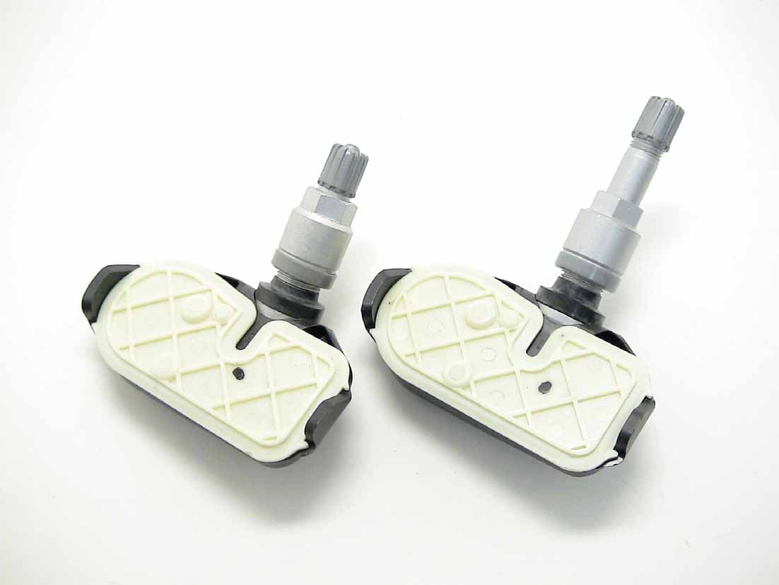
T7B-2T
Nov 11, 2006Tire Pressure Transmitter
Equipment Class
DSC - Part 15 Security/Remote Control Transmitter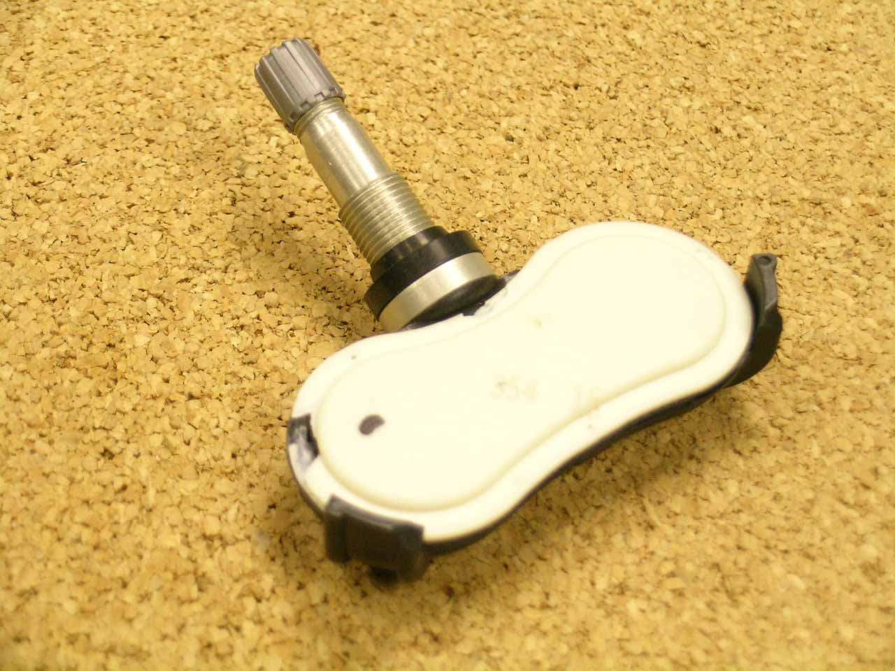
T7B-1R
Jun 20, 2006TPMS Receiver
Equipment Class
CYY - Communications Receiver used w/Pt 15 Transmitter
T7B-1T
Jun 20, 2006TPMS Transmitter
Equipment Class
DSC - Part 15 Security/Remote Control Transmitter