T8GBE9474Bluetooth Handsfree Car Kit
Harman Becker Automotive Systems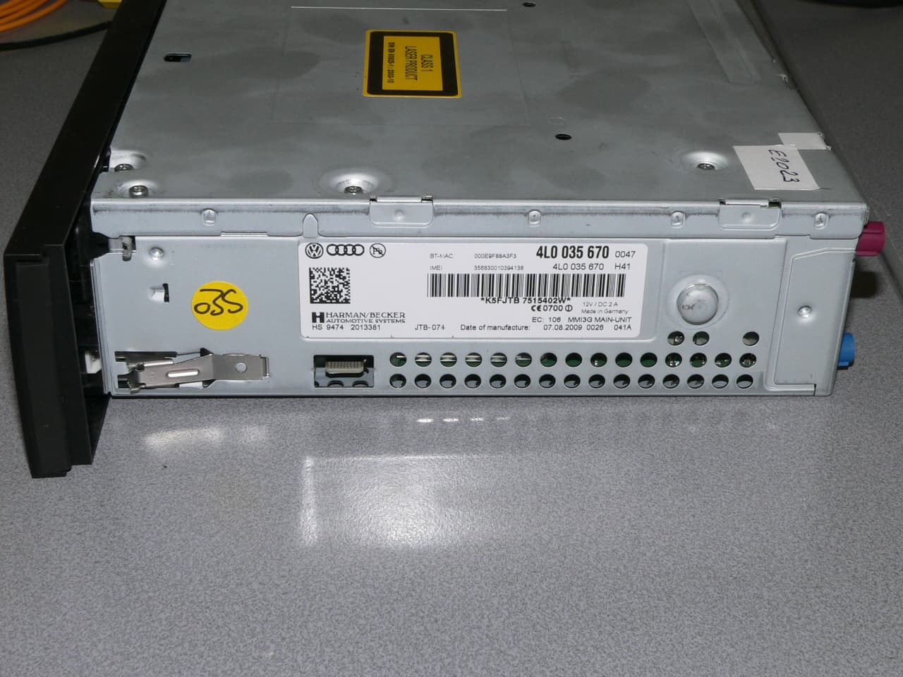
Click to zoom
Application Details
- Equipment Class
- DSS - Part 15 Spread Spectrum Transmitter
- Date of Grant
- Feb 21, 2010
- Application Purpose
- Original Equipment
- Date of Application
- Feb 21, 2010
- Equipment Note
- Bluetooth Handsfree Car Kit
- Frequency Range
- 2402.00000000 - 2480.00000000
- Country
- Germany
Documents & Files
Document Text
Text extracted from the exhibit documents filed with the FCC. Open a document above to read the original.
Users Manual
MMI Navigation plusEnglisch Nordamerika 11.2009 MMI Navigation plusOperating Instructions MMI high B 8, for internal use only © 2009 AUDI AGIt has always been Audi's policy to continuously improve its products. Audi, therefore, reserves the right to make changes in design and specifications, and to make additions or improvements in its prod-ucts without incurring any obligation to install them on products previously manufactured. Text, illustr ations and specifications in this book are based on the most up-to- date information available at the time of printing. May not be reproduced or trawritten consent of AUDI AG. A to alteration or amendment. Editorial deadline: 08/28/2 0 For the sake of the e n Printed on environmentally f r rine, recyclable) MMI high B 8, for internal use only ForewordYou have decided on the Audi MMI Navi gation plus - thank you very much for your confidence in us.With your new Audi, you are receiving a vehicle with a state-of-the art system that allows you the change the vehicle's settings and operate the electronic equipment using a Multi Media Interface called the Audi MMI . We recommend that you read these Operating Instructions carefully so that you quickly get to know all of the functions and possibilities that the MMI of fers and are able to make full use of them while driving.Please note that these operating instructions are a supplement to your vehicle Owner's Manual and should only be used in conjunction with your current vehicle Owner's Manual.Should you have any further question s about the MMI in your vehicle, please ask your authorized Audi dealer for assistance.We hope you enjoy driving your Audi.AUDI AG MMI high B 8, for internal use only Table of contents 2 Table of contentsAbout this book . . . . . . . . MMI components . . . . . . Overview . . . . . . . . . . . . . . . . . . . . . Controls at a glance . . . . . . . . . . . MMI: Multi Media Interface . . . . . Traffic safety tips . . . . . . . . . . . . . Tips on caring for the MMI . . . . . Drives . . . . . . . . . . . . . . . . . . . . . . . . Introduction . . . . . . . . . . . . . . . . . Overview of drives . . . . . . . . . . . . . CD/DVD mode general information . . . . . . . . . . . . . . . . . . Memory card general informationJukebox . . . . . . . . . . . . . . . . . . . . . . CD/DVD drive . . . . . . . . . . . . . . . . . CD changer . . . . . . . . . . . . . . . . . . . Memory card reader . . . . . . . . . . . Audi music interface . . . . . . . . . . . Aux-in connection . . . . . . . . . . . . . Cell phone prep . . . . . . . . . . . . . . . Introduction . . . . . . . . . . . . . . . . . Starting . . . . . . . . . . . . . . . . . . . . . MMI control panel . . . . General operation . . . . . . . . . . . . All MMI menus at a glance . . . . . Switching on/off . . . . . . . . . . . . . . Operating the system . . . . . . . . . . MMI Display . . . . . . . . . . . . . . . . . . Adjusting the volume . . . . . . . . . . Adjusting the sound . . . . . . . . . . . Setting the time . . . . . . . . . . . . . . Restarting the MMI (Reset) . . . . . Additional settings . . . . . . . . . . . . Listening to the radio . . . . . . . . Introduction . . . . . . . . . . . . . . . . . System information . . . . . . . . . . . Starting radio mode . . . . . . . . . . . Activating your Satellite Radio service . . . . . . . . . . . . . . . . . . . . . . Selecting frequency band . . . . . . Selecting a station from the station list . . . . . . . . . . . . . . . . . . . Selecting the station . . . . . . . . . . Scanning stations . . . . . . . . . . . . . Storing stations . . . . . . . . . . . . . . Selecting a stored station . . . . . . Moving stored stations . . . . . . . . Additional settings . . . . . . . . . . . . Playing media . . . . . . . . . . . . . . . . Introduction . . . . . . . . . . . . . . . . . Starting Media mode . . . . . . . . . . Selecting source . . . . . . . . . . . . . . Selecting a folder . . . . . . . . . . . . . Selecting a track . . . . . . . . . . . . . . Fast forward/rewind . . . . . . . . . . Next/previous track or chapter . Track information . . . . . . . . . . . . . Repeat options . . . . . . . . . . . . . . . Shuffle . . . . . . . . . . . . . . . . . . . . . . DVD main menu . . . . . . . . . . . . . . DVD full screen display . . . . . . . . DVD parental control . . . . . . . . . . Pausing/continuing playback . . . Additional settings . . . . . . . . . . . . Directory . . . . . . . . . . . . . . . . . . . . . . Introduction . . . . . . . . . . . . . . . . . .Opening the directory . . . . . . . . . .Storing a new directory entry . . .Importing directory entries . . . . .Exporting address cards . . . . . . . .Using a directory entry . . . . . . . . .Editing a directory entry . . . . . . . .Managing profiles . . . . . . . . . . . . .Additional settings . . . . . . . . . . . . Calling . . . . . . . . . . . . . . . . . . . . . . . . Introduction . . . . . . . . . . . . . . . . . .Starting Telephone mode . . . . . . .Dialing a telephone number . . . . .Answering/ignoring a call . . . . . .Ending a call . . . . . . . . . . . . . . . . . .Storing a phone number in the directory . . . . . . . . . . . . . . . . . . . . .Dialing stored phone numbers . .Deleting local call lists . . . . . . . . .Bluetooth settings . . . . . . . . . . . . .Additional settings . . . . . . . . . . . . Navigating . . . . . . . . . . . . . . . . . . . . Introduction . . . . . . . . . . . . . . . . . .Starting Navigation mode . . . . . .Entering a destination . . . . . . . . .Stopping route guidance . . . . . . .Display . . . . . . . . . . . . . . . . . . . . . . .Storing a destination . . . . . . . . . . .Loading a destination . . . . . . . . . .Additional settings . . . . . . . . . . . . Calling up traffic information . Introduction . . . . . . . . . . . . . . . . . .Calling up TMC traffic reports . . . 4677778999 11121214141617212222222628282829293334 3637384040404141424343444545464648484848494950505151525253535455 575757575…
Text truncated - open the document above for the full version.
Cover Letter(s)
Registergerichth registered in:Vorstandh Board of Directors:7 layers AG, Borsigstrasse 11 Ratingen HRB 3264Dr. Wolfgang Dahm40880 Ratingen, Germany AufsichtsratsvorsitzendehDr. Hans-Jürgen MeckelburgPhone: +49 (0) 2102 749 0 Chairman of the Supervisory Board:Fax: +49 (0) 2102 749 350 Dr. Sabine Grobeckerwww.7layers.com Annex Additional declaration part according FCC 15.247 for Bluetooth TM Devices Version: 2002-06-01 Annex - Additional declaration part according FCC 15.247 for Bluetooth devices Page 2 of 5 pages 1 Output power and channel separation of a Bluetooth device in the different operating modes: The different operating modes (data-mode, acquisition-mode) of a Bluetooth device don’t influence the output power and the channel spacing. There is only one transmitter which is driven by identical input parameters concerning these two parameters. Only a different hopping sequence will be used. For this reason the check of these RF parameters in one op-mode is sufficient. 2 Frequency range of a Bluetooth device: Hereby we declare that the maximum frequency of this device is: 2402 – 2480 MHz. This is according the Bluetooth Core Specification (+ critical errata) for devices which will be operated in the USA. This was checked during the Bluetooth Qualification tests (Test Case: TRM/CA/04-E). Other frequency ranges ( e.g. for Spain, France, Japan) which are allowed according the Core Specification are not supported by this device. 3 Co-ordination of the hopping sequence in data mode to avoid simultaneous occupancy by multiple transmitters: Bluetooth units which want to communicate with other units must be organised in a structure called piconet. This piconet consist of max. 8 Bluetooth units. One unit is the master the other seven are the slaves. The master co-ordinates frequency occupation in this piconet for all units. As the master hop sequence is derived from its BD address which is unique for each Bluetooth device, additional masters intending to establish new piconets will always use different hop sequences. 4 Example of a hopping sequence in data mode: Example of a 79 hopping sequence in data mode: 40, 21, 44, 23, 42, 53, 46, 55, 48, 33, 52, 35, 50, 65, 54, 67, 56, 37, 60, 39, 58, 69, 62, 71, 64, 25, 68, 27, 66, 57, 70, 59, 72, 29, 76, 31, 74, 61, 78, 63, 01, 41, 05, 43, 03, 73, 07, 75, 09, 45, 13, 47, 11, 77, 15, 00, 64, 49, 66, 53, 68, 02, 70, 06, 01, 51, 03, 55, 05, 04 Annex - Additional declaration part according FCC 15.247 for Bluetooth devices Page 3 of 5 pages 5 Equally average use of frequencies in data mode and behaviour for short transmissions: The generation of the hopping sequence in connection mode depends essentially on two input values: 1. LAP/UAP of the master of the connection 2. Internal master clock The LAP (lower address part) are the 24 LSB’s of the 48 BD_ADDRESS. The BD_ADDRESS is an unambiguous number of every Bluetooth unit. The UAP (upper address part) are the 24 MSB’s of the 48 BD_ADDRESS. The internal clock of a Bluetooth unit is derived from a free running clock which is never adjusted and is never turned off. For synchronisation with other units only offset are used. It has no relation to the time of the day. Its resolution is at least half the RX/TX slot length of 312.5 μs. The clock has a cycle of about one day (23h30). In most case it is implemented as 28 bit counter. For the deriving of the hopping sequence the entire LAP (24 bits), 4 LSB’s (4 bits) (Input 1) and the 27 MSB’s of the clock (Input 2) are used. With this input values different mathematical procedures (permutations, additions, XOR- operations) are performed to generate the sequence. This will be done at the beginning of every new transmission. Regarding short transmissions the Bluetooth system has the following behaviour: The first connection between the two devices is established, a hopping sequence was generated. For transmitting the wanted data the complete hopping sequence was not used. The connection ended. The second connection will be established. A new hopping sequence is generated. Due to the fact that the Bluetooth clock has a different value, because the period between the two transmission is longer (and it cannot be shorter) than the minimum resolution of the clock (312.5 μs). The hopping sequence will always differ from the first one. 6 Receiver input bandwidth and behaviour for repeated single or multiple packets: The input bandwidth of the receiver is 1 MHz. In every connection one Bluetooth device is the master and the other one is the slave. The master determines the hopping sequence (see chapter 5). The slave follows this sequence. Both devices shift between RX and TX time slot according to the clock of the master. Additionally the type of connection (e.g. single or multislot packet) is set up at the beginning of the connection. The master adapts its hopping frequency and its TX/RX timing according to the packet type of the connection. Also the slave of the connection will use these settings. Repeating of a packet has no influence on the hopping sequence. The hopping sequence generated by the master of the connection will be followed in any case. That means, a repeated packet will not be send on the same frequency, it is send on the next frequency of the hopping sequence. Annex - Additional declaration part according FCC 15.247 for Bluetooth devices Page 4 of 5 pages 7 Dwell time in data mode The dwell time of 0.3797s within a 30 second period in data mode is independent from the packet type (packet length). The calculation for a 30 second period is a follows: Dwell time = time slot length * hop rate / number of hopping channels *30s Example for a DH1 packet (with a maximum length of one time slot) Dwell time = 625 μs * 1600 1/s / 79 * 30s = 0.3797s (in a 30s period) For multislot packet the hopping is reduced according to the length of the packet. Example for a DH5 packet (with a maximum length of five time slots) Dwell time = 5 * 625 μs * 1600 * 1/5 *1/s / 79 * 30s = …
Text truncated - open the document above for the full version.
Cover Letter(s)
Product Specification Product Specification Rufa 2.4 GHz SMD Antenna Rev : AE020157-F / April 30 2004 Rufa 2.4 GHz SMD Antenna 2 (10)Subject to changes without prior notice 1. FEATURES - Designed for 2.4 GHz applications [Bluetooth TM , WiFi TM (802.11b/g), Zigbee TM , WiMedia TM etc.] - Intended for SMD mounting - Supplied in tape on reel 2. DESCRIPTION - Mobile phones - PDAs - Headsets - Laptops - PC- Cards - CF- Cards 3. APPLICATION The Rufa antenna is intended for use with all 2.4 GHz applications. The antenna requires a groundplane, i.e your device acts as an active part of the antenna and thus demand careful consideration concerning its placement TABLE OF CONTENT 1. Features ......................................................................................................................................................................... 2 2. Description ..................................................................................................................................................................... 2 3. Application ...................................................................................................................................................................... 2 4. Model names .................................................................................................................................................................. 3 5. General data ................................................................................................................................................................... 3 6. Electrical characteristics ................................................................................................................................................. 3 7. Electrical performance .................................................................................................................................................... 4 7.1 Voltage Standing Wave Ratio ............................................................................................................................... 4 7.2 3D-Radiation ........................................................................................................................................................ 4 7.3 Radiation patterns ................................................................................................................................................ 4 8. Antenna Dimensions ....................................................................................................................................................... 5 9. Antenna Foot print .......................................................................................................................................................... 5 10. Electrical interface ........................................................................................................................................................ 6 10.1 Transmission line and matching ......................................................................................................................... 6 10.2 Test board dimensions ....................................................................................................................................... 6 10.3 Test board matching ........................................................................................................................................... 6 11. Soldering ....................................................................................................................................................................... 6 11.1 Recommended soldering conditions .................................................................................................................. 6 11.2 Leadfree soldering ............................................................................................................................................. 6 12. Reliability ...................................................................................................................................................................... 7 12.1 Temperature and Humidity ................................................................................................................................. 7 12.2 Mechanical ......................................................................................................................................................... 7 12.3 Miscellaneous .................................................................................................................................................... 7 12.4 Judgement standard .......................................................................................................................................... 7 13. Hazardous Material Reguration Conformance .............................................................................................................. 7 14. Application example ...................................................................................................................................................... 8 15. Packaging ..................................................................................................................................................................... 9 15.1 Shelf storage recommendation .......................................................................................................................... 9 15.2 Tape characteristics ........................................................................................................................................... 9 15.3 Reel dimension .................................................................................................................................................. 9 15.4 Box dimensions ................................................................................................................................…
Text truncated - open the document above for the full version.
Cover Letter(s)
Consumer Information 331 Controls and equip- ment Safety first Vehicle operation Vehicle care Do-it-yourself service Technical data ment zones. Doing so will increase the risk of injury if airbags are triggered in an accident!• Before you check anything in th e engine compartment, always read and heed all WARNINGS ⇒ page 256 . Note • If items other than genuine Audi spare parts, add-on equipment and accessory items are used or if repair work is not performed according to specified methods, this can result in severe damage to your vehicle’s engine and body (such as corrosion) and adversely affect your vehicle's warranty.• If emergency repairs must be performed elsewhere, have the vehicle examined by an authorized Audi dealer as soon as possible.• The manufacturer cannot be held liable for damage which occurs due to failure to comply with these stipulations.Technical ModificationsOur guidelines must be co mplied with when technical modifications are made. Always consult an authorized Audi dealer before starting work on any modifications.This will help ensure that vehicle function, performance and safety are not impaired ⇒ . Attempting to work on electronic components and the software used with them can cause malfunctions. Because of the way elec-tronic components are interconnected with each other, such malfunctions can also have an adverse affect on other systems that are not directly involved. This means that you risk both a substantial reduction in the operational safety of your vehicle and an increased wear of vehicle parts ⇒ . Authorized Audi dealers will perfor m this work in a professional and competent manner or, in special cases, refer you to a professional company that specializes in such modifications. WARNING Improper repairs and modifications can change the way vehicle systems work and cause serious personal injury. Note If emergency repairs must be performed elsewhere, have the vehicle examined by an authorized Audi dealer as soon as possible.Declaration of Compliance, Telecommunications and Electronic SystemsRadio Frequency Devices and Radiocommunication Equipment User Manual Notice.The manufacturer is not responsible for any radio or TV interference caused by unauthorized modifications to this equipment.DevicesThe following devices each comply with FCC Part 15.19, FCC Part 15.21 and RSS-Gen Issue 1:• Convenience key* • Audi side assist* • Cell phone package* • Electronic immobilizer • HomeLink® universal remote control* • Remote control key WARNING (continued) s1k4.book Seite 331 Freitag, 5. September 2008 3:59 15 Consumer Information 332 • Tire pressure monitoring system* FCC Part 15.19This device complies with part 15 of the FCC Rules. Operation is subject to the following two conditions:(1) This device may not cause harmful interference, and(2) this device must accept any interference received, including interference that may cause undesired operation.FCC Part 15.21CAUTION:Changes or modifications not expressly approved by the party responsible for compliance could void the user's authority to operate the equipment.RSS-Gen Issue 1Operation is subject to the following two conditions:(1) this device may not cause interference, and(2) this device must accept any interference, including interference that may cause undesired operation of the device. s1k4.book Seite 332 Freitag, 5. September 2008 3:59 15
Test Report
7 layers AG Aufsichtsratsvorsitzenderh Registergerichth registered in: Borsigstrasse 11 Chairman of the Supervisory Board: Düsseldorf, HRB 44096 40880 Ratingen, Germany Markus Becker USt-IdNr h VAT No.: Phone: +49 (0) 2102 749 0 Vorstandh Board: DE 203159652 Fax: +49 (0) 2102 749 350 Dr. Hermann Buitkamp TAX No. 147/5869/0385 www.7Layers.com Wilfried Klassmann InterLab ® is a registered trademark of 7 layers AG FCC Measurement/Technical Report on Bluetooth transceiver 3G-Sound 9474 Report Reference: MDE_HARMAN_0904_FCCa Test Laboratory: 7 layers AG Borsigstrasse 11 40880 Ratingen Germany email: [email protected] DAT-P-192/99-01 Note: The following test results relate only to the devices specified in this document. This report shall not be reproduced in parts without the written approval of the testing laboratory. Test report Reference: MDE_HARMAN_0904_FCCa Page 2 of 88 Table of Contents 0 Summary 3 0.1 Technical Report Summary 3 0.2 Measurement Summary 4 1 Administrative Data 7 1.1 Testing Laboratory 7 1.2 Project Data 7 1.3 Applicant Data 7 1.4 Manufacturer Data 7 2 Test object Data 8 2.1 General EUT Description 8 2.2 EUT Main components 9 2.3 Ancillary Equipment 9 2.4 EUT Setups 9 2.5 Operating Modes 10 2.6 Product labelling 10 3 Test Results 11 3.1 Occupied bandwidth 11 3.2 Peak power output 14 3.3 Spurious RF conducted emissions 17 3.4 Spurious radiated emissions 20 3.5 Band edge compliance 26 3.6 Dwell time 30 3.7 Channel separation 32 3.8 Number of hopping frequencies 34 4 Test Equipment 35 5 Photo Report 41 6 Setup Drawings 44 7 Annex measurement plots 45 7.1 Occupied bandwidth 45 7.2 Peak power output 54 7.3 Band edge compliance conducted and Spurious RF conducted emissions 63 7.4 Band edge compliance radiated 81 7.5 Radiated emissions (f < 30 MHz) 84 7.6 Dwell time 86 7.7 Channel separation 87 7.8 Number of hopping frequencies 88 Test report Reference: MDE_HARMAN_0904_FCCa Page 3 of 88 0 Summary 0.1 Technical Report Summary Type of Authorization Certification for an Intentional Radiator (Frequency Hopping Spread Spectrum). Applicable FCC Rules Prepared in accordance with the requirements of FCC Rules and Regulations as listed in 47 CFR Ch.1 Parts 2 (10-1-08 Edition) and 15 (10-1-08 Edition). The following subparts are applicable to the results in this test report. Part 2, Subpart J - Equipment Authorization Procedures, Certification Part 15, Subpart C – Intentional Radiators § 15.201 Equipment authorization requirement § 15.207 Conducted limits § 15.209 Radiated emission limits; general requirements § 15.247 Operation within the bands 902-928 MHz, 2400-2483.5 MHz and 5725-5850 MHz Note: The tests were selected and performed with reference to the FCC Public Notice DA 00- 705, released March 30, 2000. Instead of applying ANSI C63.4-1992 which is referenced in the FCC Public Note, the newer ANSI C63.4-2003 is applied. Summary Test Results: The EUT complied with all performed tests as listed in chapter 0.2 Measurement Summary. Test report Reference: MDE_HARMAN_0904_FCCa Page 4 of 88 0.2 Measurement Summary FCC Part 15, Subpart C § 15.207 Conducted emissions (AC power line) The measurement was performed according to ANSI C63.4 2003 OP-Mode Setup Port Final Result AC Port (power line) N/A FCC Part 15, Subpart C § 15.247 (a) (1) Occupied bandwidth The measurement was performed according to FCC § 15.31 10-1-08 OP-Mode Setup Port Final Result op-mode 1 Setup_b01 Temp ant.connector passed op-mode 2 Setup_b01 Temp ant.connector passed op-mode 3 Setup_b01 Temp ant.connector passed op-mode 6 Setup_b01 Temp ant.connector passed op-mode 7 Setup_b01 Temp ant.connector passed op-mode 8 Setup_b01 Temp ant.connector passed op-mode 10 Setup_b01 Temp ant.connector passed op-mode 11 Setup_b01 Temp ant.connector passed op-mode 12 Setup_b01 Temp ant.connector passed FCC Part 15, Subpart C § 15.247 (b) (1) Peak power output The measurement was performed according to FCC § 15.31 10-1-08 OP-Mode Setup Port Final Result op-mode 1 Setup_b01 Temp ant.connector passed op-mode 2 Setup_b01 Temp ant.connector passed op-mode 3 Setup_b01 Temp ant.connector passed op-mode 6 Setup_b01 Temp ant.connector passed op-mode 7 Setup_b01 Temp ant.connector passed op-mode 8 Setup_b01 Temp ant.connector passed op-mode 10 Setup_b01 Temp ant.connector passed op-mode 11 Setup_b01 Temp ant.connector passed op-mode 12 Setup_b01 Temp ant.connector passed FCC Part 15, Subpart C § 15.247 (d) Spurious RF conducted emissions The measurement was performed according to FCC § 15.31 10-1-08 OP-Mode Setup Port Final Result op-mode 1 Setup_b01 Temp ant.connector passed op-mode 2 Setup_b01 Temp ant.connector passed op-mode 3 Setup_b01 Temp ant.connector passed op-mode 6 Setup_b01 Temp ant.connector passed op-mode 7 Setup_b01 Temp ant.connector passed op-mode 8 Setup_b01 Temp ant.connector passed op-mode 10 Setup_b01 Temp ant.connector passed op-mode 11 Setup_b01 Temp ant.connector passed op-mode 12 Setup_b01 Temp ant.connector passed Test report Reference: MDE_HARMAN_0904_FCCa Page 5 of 88 FCC Part 15, Subpart C § 15.247 (d), § 15.35 (b), § 15.209 Spurious radiated emissions The measurement was performed according to ANSI C63.4 2003 OP-Mode Setup Port Final Result op-mode 1 Setup_a01 Enclosure passed op-mode 2 Setup_a01 Enclosure passed op-mode 3 Setup_a01 Enclosure passed op-mode 6 Setup_a01 Enclosure passed op-mode 7 Setup_a01 Enclosure passed op-mode 8 Setup_a01 Enclosure passed op-mode 10 Setup_a01 Enclosure passed op-mode 11 Setup_a01 Enclosure passed op-mode 12 Setup_a01 Enclosure passed FCC Part 15, Subpart C § 15.247 (d) Band edge compliance The measurement was performed according to FCC § 15.31 (10-1-08) / ANSI C63.4 (2003) 10-1-08 / 2003 OP-Mode Setup Port Final Result op-mode 1 Setup_b01 Temp ant.connector passed op-mode 3 Setup_b01 Temp ant.connector passed op-mode 3 Setup_a01 Enclosure passed op-mode 6 Setup_b01 Temp ant.connector passed op-mode 8 Setup_b01 Temp ant.connector passed op-mode 8 Setup_a01 Enclosure passed op-mode 10 S…
Text truncated - open the document above for the full version.
Contact Information
Applicant
Simon David Voegele
Test Firm
7layers AGRobert Machulec
Technical Specifications
| # | Rule Parts | Frequency Range | Power Output |
|---|---|---|---|
| 1 | 15C | 2.40 GHz - 2.48 GHz | 1.50 mW |
Other Applications from Harman Becker Automotive Systems
T8GIDCEVOEES25
Feb 24, 2026Automotive infotainment System IDC
Equipment Class
NII - Unlicensed National Information Infrastructure TX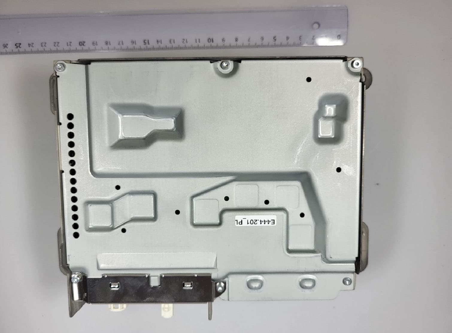
T8GNTG7QPREPLU
Jul 20, 2023Automotive head unit to be installed in cars with the following features FM, AM, DAB, DVB, USB, Bluetooth, WLAN and GNSS
Equipment Class
DTS - Digital Transmission System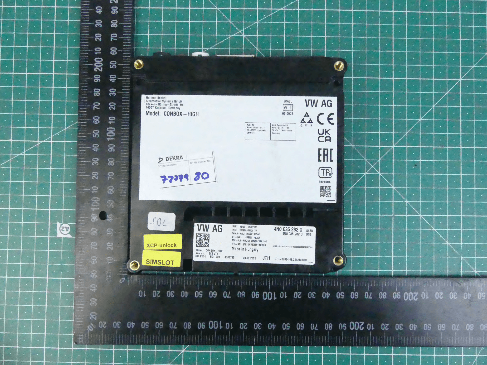
T8GCONBOXRD
May 04, 2023Telematic control unit with wireless technologies, used in automotive industry.
Equipment Class
DSS - Part 15 Spread Spectrum Transmitter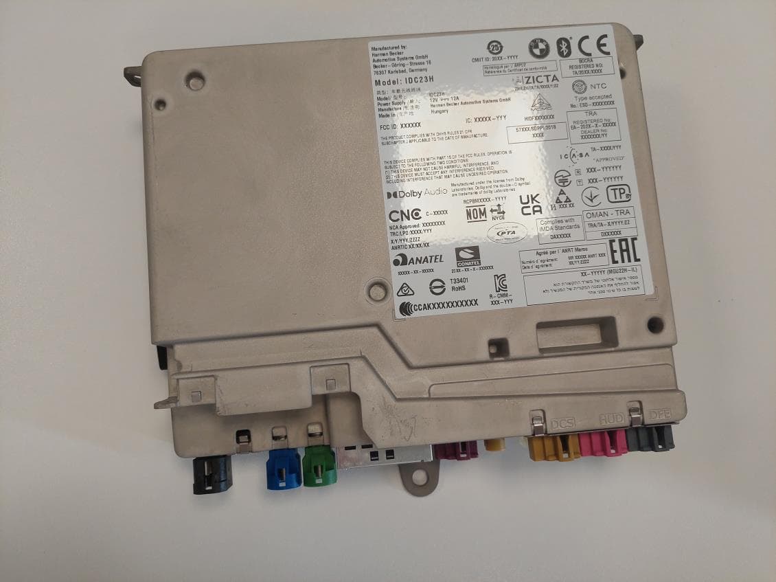
T8GIDC23H
Mar 29, 2023Automotive head unit to be installed in cars with the following features Bluetooth EDR LE WLAN and GNSS
Equipment Class
DSS - Part 15 Spread Spectrum Transmitter
T8GCONMOD
Jan 19, 2023Telematic control unit with wireless technologies, used in automotive industry.
Equipment Class
DTS - Digital Transmission System