T8I-DELTA-ARFID Reader
Farpointe Data Inc.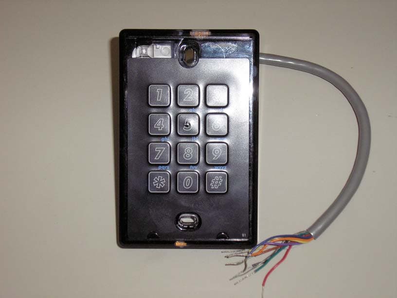
Click to zoom
Application Details
- Equipment Class
- DXX - Part 15 Low Power Communication Device Transmitter
- Date of Grant
- Mar 10, 2008
- Application Purpose
- Original Equipment
- Date of Application
- Mar 10, 2008
- Equipment Note
- RFID Reader
- Frequency Range
- 13.56000000 - 13.56000000
- Company
- Farpointe Data Inc.
- Country
- United States
Documents & Files
Document Text
Text extracted from the exhibit documents filed with the FCC. Open a document above to read the original.
Users Manual
Delta Multi-Technology Readers: Quick Reference Guide 2177 Leghorn Street 01609-001 Rev 1.0 Mountain View, CA 94043-1605 USA 1 of 2 Tel: +1-650-964-2615 Fax: +1-650-988-6687 Web: http://www.farpointedata.com E-mail: [email protected] The Delta multi-technology models include the Delta3, Delta5, Delta5.3, and Delta 6.4. All Delta multi-technology readers are compliant with the following organizations: FCC compliance Statement: This device complies with part 15 of the FCC rules. Operation is subject to the following two conditions: (1) this device may not cause harmful interference, and (2) this device must accept any interference received, including interference that may cause undesired operation. The user is cautioned that making changes not approved by Farpointe Data may void the user's authority to use this equipment. 1.0 Cable Requirements All readers operate at up to 500 feet (152 m) of cable, using nine-conductor, shielded, stranded cable. Per the Security Industry Association’s Wiegand specification, AWG 24 (such as Belden 9539) is the minimum gauge required for data transfer in a 500-foot run length. However, the proper wire gauge must be determined by the current draw requirements of the reader, the length of the cable run, and the voltage applied to the reader. If the reader is to be operated at 5 VDC, 5 VDC must be available at the reader (long cable runs have a voltage drop due to the resistance in the cable). A larger gauge of wire (having less resistance) or a separate power supply near the reader may be required to ensure 5 VDC is available at the reader. 2.0 Delta Multi-Technology Credential Compatibility Delta multi-technology readers are capable of reading both 13.56 MHz and 125 kHz RFID credentials. Operating at 13.56 MHz the reader can read all ISO 14443 Type A contactless smartcard credentials (some are card serial number (CSN) only) and some ISO 14443 Type B contactless smartcard credentials. These credentials include Mifare 1K/4K (secure sectors or CSN), Mifare Ultralight (CSN only), Mifare DESfire (CSN Only), and both Type A and Type B PIV credentials (FIPS-201 compliant). Operating at 125 kHz Delta multi-technology readers can optionally read Pyramid, HID, and/or AWID 125 kHz proximity credentials. 125 kHz reading capability can be disabled if desired. 3.0 Contactless Smartcard Reader Modes Delta multi-technology readers can be configured to read contactless smartcards in any of the following modes: • Sector Plus CSN Mode: Reader looks for access control data in a secure sector but if none is found the reader outputs the card’s CSN instead. This is the default mode. • Sector Only Mode: Reader looks for access control data in a secure sector but if no valid data is found the reader outputs nothing. • CSN Only Mode: Reader does not look for access control data in a secure sector and simply outputs the card’s CSN. 4.0 14443 Type A CSN Output Formats Delta multi-technology readers can be configured to output 14443 Type A CSNs in any of the following ways: • 32-bit Wiegand: The reader outputs the 32-bit CSN as Wiegand data starting with the MSB. This is the default mode. • 26-bit Wiegand: The reader outputs 26-bit Wiegand data comprised of the 16 lower bits of the 32-bit CSN, fixed 8-bit facility code, and beginning and ending parity bits. Facility code defaults to 001 (Note: cutting off 16 MSBs from CSN can cause card duplication). • 34-bit Wiegand: The reader outputs 34-bit Wiegand data comprised of the 32-bit CSN MSB first plus beginning and ending parity bits. • 40-bit Wiegand: The reader outputs 40-bit Wiegand data comprised of the 32-bit CSN followed by an 8-bit check sum. • Magnetic Stripe (ABA Track II, clock and data, with card present): CSN is output in ABA Track II format. 5.0 Secure Sector Access Control Data Output Formats Customer specified access control data programmed onto a secure Mifare 1K or 4K sector can be output in any of the following ways: • Wiegand (industry standard 26-bit Wiegand and custom formats) • Magnetic Stripe (ABA Track II, clock and data, with card present) 6.0 FIPS-201 Output Formats Please see Farpointe Data’s “FIPS-201 Reader Output Selection” document. Default output is 75-bit Wiegand. Reference Documen t Delta Multi- T echnology R eader s Delta Multi-Technology Readers: Quick Reference Guide 2177 Leghorn Street 01609-001 Rev 1.0 Mountain View, CA 94043-1605 USA 2 of 2 Tel: +1-650-964-2615 Fax: +1-650-988-6687 Web: http://www.farpointedata.com E-mail: [email protected] 7.0 Grounding Shield (drain) continuity must run from the reader to the access panel. Shield (drain) and reader ground must be tied together at the access panel and connect to an earth ground at one point. 8.0 Power and Voltage Delta multi-technology readers may be powered by the access panel, so the reader is powered on when the access supply is powered on. However the best case is to power the readers by a separate, linear power supply. Voltage can range from 5 to 14 VDC, 12 VDC is nominal. 9.0 Reader Wiring 10.0 Connections in Detail Wire Color Line I/O Description Red Reader input voltage Input 5 to 14 VDC Green Wiegand data 0/ Magstripe Clock Output Wiegand data or ABA Track II clock White Wiegand data 1/ Magstripe Data Output Wiegand data or ABA Track II data Brown Red LED host control Input LED host control. In single line LED control mode (default mode) pull line low to turn on green LED. In dual line LED mode pull line low to turn on Red LED Orange Green LED host control Input LED host control, only used in dual LED mode. In dual LED mode pull line low to turn on green LED. Blue Audio tone host control Input Beeper host control. Pull line low for beep. Purple Read mode control Input Read mode host control. Pull line low for “Sector Only” mode. Yellow Card Present Output (can be configured as TTL or open collector) Card present line for ABA Track II magnetic stripe output. Black Reader Ground Input Reader Ground Silver Cable shield N/A Cable sh…
Text truncated - open the document above for the full version.
Attestation Statements
tel: 650-726-1263 fax: 650-726-1252 [email protected] Thomas N. Cokenias EMC &Radio Approvals Test & Consulting Services for Commercial, Military, International Compliance P.O. Box 1086 El Granada, CA 94018 email: [email protected] Compliance Certification Services 5 March 2008 47173 Benicia Street Fremont CA 94538 Attention: Applications Examiner Re: FCC and Industry Canada Certification Application for Farpointe Data Inc. Equipment: Dual Frequency 0.125/13.56 MHz Proximity RFID Reader FCC ID: T8I-DELTA-A IC: 6504A-DELTA-A Model Numbers: Delta3 Multi-Technology Delta5 Multi-Technology Delta6.4 Multi-Technology Hello, Farpointe Data Inc. is submitting applications for certification of a dual frequency RFID reader line. The reader uses a 13.56 MHz CW emission and a 125 kHz pulsed emission. The RF circuit is the same for all three models. The highest power is for model Delta5 Multi-Technology as it has the largest coil. Minor non-RF differences exist for different products to accommodate different status LEDs, beepers, and attachment points for Part 15 verified keyboards. The Delta3 model is identical to the Delta5 model except that it has a smaller coil size. The Delat6.4 model is a Delta5 reader with a Part 15 class B verified keyboard incorporated in the front face. If you have questions or need further information, please don’t hesitate to contact me. Sincerely T.N. Cokenias Agent for Farpointe Data Inc.
Cover Letter(s)
tel: 650-726-1263 fax: 650-726-1252 [email protected] Thomas N. Cokenias EMC &Radio Approvals Test & Consulting Services for Commercial, Military, International Compliance P.O. Box 1086 El Granada, CA 94018 email: [email protected] Compliance Certification Services 16 February 2008 47173 Benicia Street Fremont, CA 94538 Attention: Mike Kuo Re: Request for confidentiality per 0.457 of FCC Rules Applicant: Farpointe Data Inc. FCC ID: T8I-DELTA-A IC: 6504A-DELTA-A Dear Mike, On behalf of my client Farpointe Data Inc., I request the following documents associated with this application for certification be withheld from public view: Schematics Block diagrams Operational description Internal photographs Justification for including internal photographs in confidentiality request: In final assembly all circuits are surrounded by opaque potting material, Removing this material to inspect circuits will likely destroy circuits imbedded in the potting material. Farpointe Data Inc. has expended considerable time and funds in developing the referenced product, and disclosure of these documents to competitors would afford them an unfair advantage in developing similar competing products. If you have questions or need further information please don’t hesitate to contact me. Sincerely, T.N. Cokenias Agent for Farpointe Data Inc.
External Photos
EXTERNAL PHOTOGRAPHS Grantee: Farpointe Data Inc. FCC ID: T8I-DELTA-A Delta3 Multi-Technology Delta5 Multi-Technology Delta6.4 Multi-Technology
ID Label/Location Info
LABEL AND LABEL PLACEMENT FarPointe Data Systems FCC ID: T8I-DELTA-A IC: 6504A-DELTA-A Models: Delta3-Multi-Technology, Delta5-Multi-Technology, Delta6.4 Multi-Technology FCC ID: T8I-DELTA-A IC: 6504A-DELTA-A This device complies with Part 15 of the FCC Rules. Operation is subject to the following two conditions: (1) This device may not cause harmful interference, and (2) This device must accept any interference received, including interference than may cause undesired operation Model No.: DeltaX Multi-Technology
Test Report
Farpointe Data FCC ID: T8I-DELTA-A Report No. 08PR002FCC 5 March 2008 page1 Test Report for Unlicensed Low Power Transmitter FCC Applicable Rule Parts: 15.205, 15.207, 15.209 Applicant: Farpointe Data Inc. 2177 Leghorn Street Mountain View, CA 94043 FCC ID: T8I-DELTA-A Model Nos.: Delta3 Multi-Technology Delta5 Multi-Technology Delta6.4 Multi-Technology Description of device: The DELTA Series Proximity line of OEM proximity readers, cards, and tags are dual frequency, non-contact, identification solutions based upon the latest techniques in radio frequency identification (RFID). The proximity reader has a receiver circuit, a microprocessor, a 125 kHz pulsed exciter and a 13.56 MHz CW exciter circuit that includes a magnetic coil. The tags and cards that are read by the reader have a highly reliable radio frequency integrated circuit (RFIC), attached to a magnetic coil inside a durable, environmentally secure plastic housing. The referenced models all use the same RF transmit and receive circuits, the differences among models consist of coil size, non-RF features such as keypads, and form factors. Model Delta5 Multi-Technology has the largest coil and the highest output power at the fundamental frequencies. Model Delta6.4 Multi-Technology is a Delta5 with a digital keypad entry and is worst-case representative for both radiated and line conducted emissions. Model Delta3 Multi-Technology is identical to model Delta5 with a smaller coil and lower radiated emissions at the fundamental. TEST REQUIREMENTS The referenced device is subject to certification under Part 2 of FCC Rules. The specific emissions limits and test requirements are found in Part 15 of FCC Rules. In addition to the device specific requirements listed in 15.225 (re-printed below), the following Part 15 requirements are universal to all unlicensed transmitters and would also apply: 15.19 Labeling requirements 15.20 Accessories 15.21 Information to user 15.31 Measurement standards 15.33 Frequency range of measurements 15.35 Measurement detector functions and bandwidths Farpointe Data FCC ID: T8I-DELTA-A Report No. 08PR002FCC 5 March 2008 page2 15.109 Radiated Emissions (unintentional radiators) 15.203 Antenna requirement 15.204 External radio frequency power amplifiers and antenna modifications. 15.205 Restricted bands of operation. 15.207 Conducted limits 15.209 Radiated emission limits, general requirements. 15.225 Operation within the band 13.110 – 14.010 MHz REVISION INFORMATION AND ATTESTATION OF RESULTS Report No: 06PR048FCC REV No. Description Revised By: Date - Original Issue T. Cokenias 3/5/2008 FCC ID: T8I-DELTA-A meets all FCC requirements for a device of this type. THOMAS N. COKENIAS 5 March 2008 EMC and Radio Regulatory Consultant Agent for Farpointe Data Inc. Farpointe Data FCC ID: T8I-DELTA-A Report No. 08PR002FCC 5 March 2008 page3 15.205 Restricted bands of operation. Only spurious emissions are permitted in any of the frequency bands listed below: The field strength of emissions appearing within these frequency bands shall not exceed the limits shown in Section 15.209. MHz MHz MHz GHz 0.090 - 0.110 10.495 - 0.505 2.1735 - 2.1905 4.125 - 4.128 4.17725 - 4.17775 4.20725 - 4.20775 6.215 - 6.218 6.26775 - 6.26825 6.31175 - 6.31225 8.291 - 8.294 8.362 - 8.366 8.37625 - 8.38675 8.41425 - 8.41475 12.29 - 12.293 12.51975 - 12.52025 12.57675 - 12.57725 13.36 - 13.41 16.42 - 16.423 16.69475 - 16.69525 16.80425 - 16.80475 25.5 - 25.67 37.5 - 38.25 73 - 74.6 74.8 - 75.2 108 - 121.94 123 - 138 149.9 - 150.05 156.52475 - 156.52525 156.7 - 156.9 162.0125 - 167.17 167.72 - 173.2 240 - 285 322 - 335.4 399.9 - 410 608 - 614 960 - 1240 1300 - 1427 1435 - 1626.5 1645.5 - 1646.5 1660 - 1710 1718.8 - 1722.2 2200 - 2300 2310 - 2390 2483.5 - 2500 2655 - 2900 3260 - 3267 3332 - 3339 3345.8 - 3358 3600 - 4400 4.5 - 5.15 5.35 - 5.46 7.25 - 7.75 8.025 - 8.5 9.0 - 9.2 9.3 - 9.5 10.6 - 12.7 13.25 - 13.4 14.47 - 14.5 15.35 - 16.2 17.7 - 21.4 22.01 - 23.12 23.6 - 24.0 31.2 - 31.8 36.43 - 36.5 15.209 Radiated emission limits, general requirements. Except as provided elsewhere in this paragraph the emissions from an intentional radiator shall not exceed the field strength levels specified in the following table: Frequency (MHz) Field Strength uV/m Measurement distance, m 0.009 - 0.490 0.490 - 1.705 1.705 - 30.0 30 - 88 88 - 216 216 - 960 Above 960 2400/F(kHz) 24000/F (kHz) 30 100 ** 150 ** 200 ** 500 300 30 30 3 3 3 3 ** Except as provided in paragraph (g), fundamental emissions from intentional radiators operating under this Section shall not be located in the frequency bands 54-72 MHz, 76-88 MHz, 174-216 MHz or 470-806 MHz. Farpointe Data FCC ID: T8I-DELTA-A Report No. 08PR002FCC 5 March 2008 page4 15.225 Operation within the band 13.110 – 14.010 MHz. (a) The field strength of any emissions within the band 13.553-13.567 MHz shall not exceed 15,848 microvolts/meter (= 84 dBuV/m) at 30 meters. (b) Within the bands 13.410-13.553 MHz and 13.567-13.710 MHz, the field strength of any emissions shall not exceed 334 microvolts/meter (=50.5dBuV/m) at 30 meters. (c) Within the bands 13.110-13.410 MHz and 13.710-14.010 MHz the field strength of any emissions shall not exceed 106 microvolts/meter (=40.5 dBuV/m) at 30 meters. (d) The field strength of any emissions appearing outside of the 13.110-14.010 MHz band shall not exceed the general radiated emission limits in § 15.209. (e) The frequency tolerance of the carrier signal shall be maintained within +/- 0.01% of the operating frequency over a temperature variation of –20 degrees to +50 degrees C at normal supply voltage, and for a variation in the primary supply voltage from 85% to 115% of the rated supply voltage at a temperature of 20 degrees C. For battery operated equipment, the equipment tests shall be performed using a new battery. (f) In the case of radio frequency powered tags designed to operate with a device authorized under this section, the tag may be approved with the device or be consi…
Text truncated - open the document above for the full version.
Test Setup Photos
Farpointe Data FCC ID: T8I-DELTA-A Report No. 08PR002FCC 5 March 2008 page32 Test Set-Up Photographs Radiated emissions below 30 MHz, 10m separation Farpointe Data FCC ID: T8I-DELTA-A Report No. 08PR002FCC 5 March 2008 page33 Radiated Emissions Below 30 MHz, 3m separation Farpointe Data FCC ID: T8I-DELTA-A Report No. 08PR002FCC 5 March 2008 page34 Radiated Emissions, 30 – 1000 MHz, Front View Farpointe Data FCC ID: T8I-DELTA-A Report No. 08PR002FCC 5 March 2008 page35 AC Line Conducted Emissions Farpointe Data FCC ID: T8I-DELTA-A Report No. 08PR002FCC 5 March 2008 page36 Frequency Stability
Contact Information
Applicant
Kirk Bierach(Director of Engineering)
Test Firm
Compliance Certification ServicesThu Chan
Technical Specifications
| # | Rule Parts | Frequency Range | Power Output |
|---|---|---|---|
| 1 | 15C | 13.56 MHz - 13.56 MHz | - |
Other Applications from Farpointe Data Inc.
T8I-CONEKT6
Apr 02, 2026BLE and HF Access Control Module
Equipment Class
DXX - Part 15 Low Power Communication Device Transmitter
T8I-CONEKT4
Dec 28, 2020NORTEK MOBILE-READY PROXIMITY READERS
Equipment Class
DTS - Digital Transmission System
T8I-CONEKT5
Dec 28, 2020NORTEK MOBILE-READY CONTACTLESS SMARTCARD READER
Equipment Class
DTS - Digital Transmission System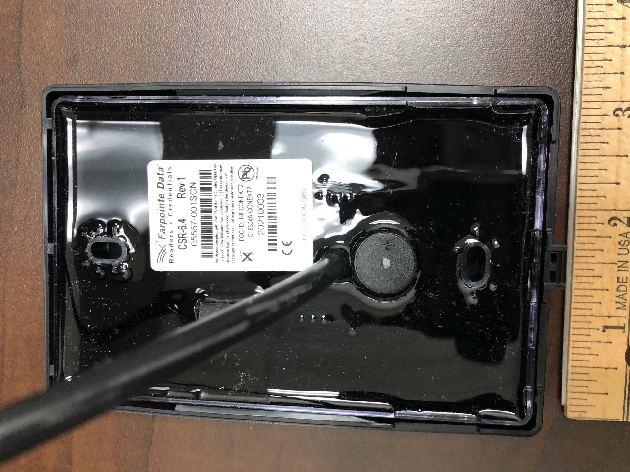
T8I-CONEKT2
Aug 06, 2020CONEKT MOBILE-READY CONTACTLESS SMARTCARD READER
Equipment Class
DXX - Part 15 Low Power Communication Device Transmitter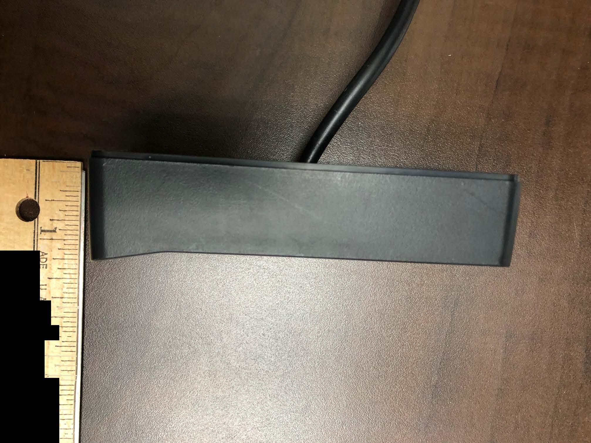
T8I-CONEKT3
Jul 28, 2020CONEKT MOBILE-READY PROXIMITY READERS
Equipment Class
DXX - Part 15 Low Power Communication Device Transmitter