T8I-PYRAMIDProximity RFID Reader
Farpointe Data Inc.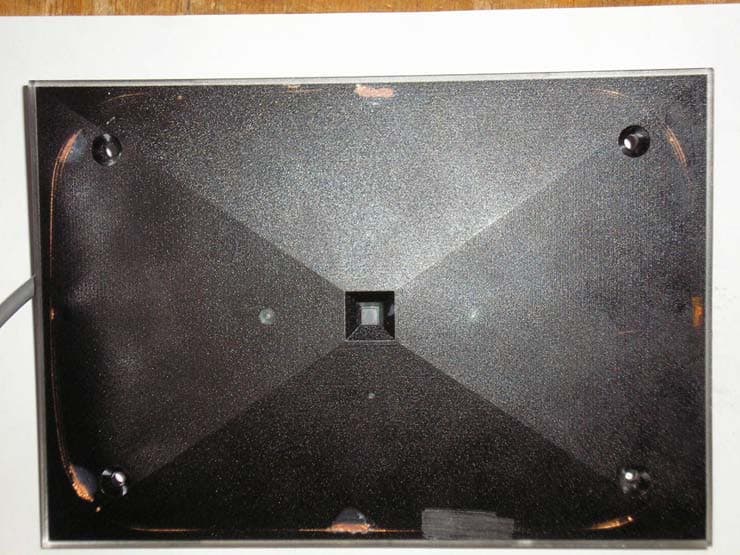
Click to zoom
Application Details
- Equipment Class
- DCD - Part 15 Low Power Transmitter Below 1705 kHz
- Date of Grant
- Oct 16, 2006
- Application Purpose
- Original Equipment
- Date of Application
- Oct 16, 2006
- Equipment Note
- Proximity RFID Reader
- Frequency Range
- 0.12500000 - 0.12500000
- Company
- Farpointe Data Inc.
- Country
- United States
Documents & Files
Document Text
Text extracted from the exhibit documents filed with the FCC. Open a document above to read the original.
Users Manual
Pyramid Series Proximity Readers 2177 Leghorn Street 01566-002 Rev. 1.2 Mountain View, CA 94043-1605 USAPage 1 of 22 Tel: +1-650-964-2615 Fax: +1-650-988-6687 Web: http://www.pyramidseries.com E-mail: [email protected] Pyramid Series Product Manual The Pyramid Series Proximity line of OEM Proximity Readers can be used with virtually any manufacturer's access panel because the readers produce industry standard pass-through Wiegand (26-bit or custom formats) or magnetic stripe output. Readers can be configured to work with access panels using either single or dual LED control lines. Optionally, Pyramid Series readers can be configured in the factory to read standard formatted HID credentials 1 . Pyramid Series readers are able to read the following Pyramid Series credentials. • PSC-1 Standard Light Proximity Cards • PSM-2 Multi Technology Cards •PSK-3 Proximity Key Tags When a card or tag is read, a Pyramid Series reader immediately responds with a beep and an LED flash 2 . The access panel then handles subsequent LED and beeper responses. Both the beep and the flash in this "Beep-n-Flash" feature can be disabled. Pyramid Series readers also feature built-in diagnostics: a start-up self test to ensure reader functionality and a data line test to ensure reader/access panel communication. The Pyramid Series features five readers, each with its own unique characteristics, to meet virtually any requirements an end-user may have. •The P-300 Cascade Proximity Reader is intended for installation on a window mullion or a door frame, in proximity applications where an unobtrusive reader is required. It can be mounted on metal or non-metal surfaces without loss of read range. •The P-400 Gibraltar Proximity Reader is intended for mounting on a flat surface or a solid metal surface, in proximity applications where a vandal-resistant reader is required. •The P-500 Alps Proximity Reader is intended for mounting on a flat non-metal surface or on a standard U.S. single-gang electrical box (if the electrical box is metal, the provided standoff must be used). •The P-600 Rocky Proximity Reader and Keypad combines a Pyramid Series reader and a stainless steel Essex Keypad TM into one attractive package. The P-600 reader can be used in applications requiring single verification, either via proximity access or PIN, but it is typically used in applications requiring dual verification - an individual requesting access to a secure area must have both a valid proximity access 1. See Section 1.0 HID Compatibility for more information. 2. The P-400 Gibraltar Proximity Reader does not have an LED to maximize its vandal resistance. Pyramid Series Proximity Readers 2177 Leghorn Street01566-002 Rev. 1.2 Mountain View, CA 94043-1605 USAPage 2 of 22 Tel: +1-650-964-2615 Fax: +1-650988-6687 Web: http://www.pyramidseries.com E-mail: [email protected] Product Manual Pyramid Series credential and a valid Personal Identification Number (PIN). To use the P-600 reader for dual verification the access panel must be capable of handling the Wiegand format for the proximity section and either the 8-bit burst or 26-bit Wiegand format for the keypad section. The P-600 is designed for mounting on a flat, non-metal surface or on a standard U.S. single-gang electrical box. •The P-700 Yukon Reader is intended for mounting where a longer read range contributes to the convenience of the access system; such as parking lots, employee entrances, and physically challenged (ADA requirement) access applications. Due to the reader’s longer read range, care must be taken in mounting the reader in environments where metal and sources of electromagnetic or radio frequency interference is present. The electronics for the P-300, P-500, P-600, and P-700 readers is housed in a weatherproof, shock resistant package. This package is mounted to the installation surface. An attractive, snap-on, scratch-resistant, black or off-white front cover hides the electronics package and installation mounting hardware providing an extra level of security. The electronics for the P-400 reader is housed in a stainless steel package, designed to be weather, vandal, and bullet resistant. All Pyramid Series readers are compliant with the following organizations: -FCC - (see Footnote 1 ) - FCC compliance Statement: This device complies with part 15 of the FCC rules. Operation is subject to the following two conditions: 1. this device may not cause harmful interference, and 2. this device must accept any interference received, including interference that may cause undesired operation. NOTE: The user is cautioned that making changes not approved by Farpointe Data may void the user's authority to use this equipment. 1. This product can be used without license conditions or restrictions in all European Union member countries including Austria, Belgium, Denmark, Finland, France, Germany, Greece, Ireland, Italy, Luxembourg, The Netherlands, Portugal, Spain, Sweden, The United Kingdom, as well as other non-EU countries including Iceland, Norway, and Switzerland. Pyramid Series Proximity Readers 2177 Leghorn Street 01566-002 Rev. 1.2 Mountain View, CA 94043-1605 USAPage 3 of 22 Tel: +1-650-964-2615 Fax: +1-650-988-6687 Web: http://www.pyramidseries.com E-mail: [email protected] Pyramid Series Product Manual 1.0 HID Compatibility Pyramid Series readers can be configured in the factory to read HID’s standard proximity access control cards, including the ProxCard II, ISOProx II, and ProxKey II in 26-bit and other Wiegand formats, as well as all Pyramid Series credentials. Readers configured to be HID compatible, an optional feature, will have the following sticker on the back side of the reader. When ordering readers that are HID compatible, the letter “H” will be added to the reader name identifying it as HID compatible. For example, the P-300 reader that is HID compatible will be called P-300H. HID compatible Pyramid Series Readers do not require any special wiring c…
Text truncated - open the document above for the full version.
Users Manual
Farpointe Data Readers 2177 Leghorn Street01506-001 - Rev. 1.3 Mountain View, CA 94043-1605 USA1 of 2 Tel: +1-650-964-2615 Fax: +1-650-988-6687 Web: www.pyramidseries.com E-mail: [email protected] Installation Guide Proximity Readers This Installation Guide is intended for experienced installing technicians. It is a basic reference to ensure all connections are properly made. See the appropriate Product Manual for detailed information on installing Pyramid Series Readers or Cobra Readers (such as the P-300, P-500, P-640, P-700, or EM-30, EM-50, EM-64). These documents may be downloaded from the Farpointe Data website found at www.pyramidseries.com; under Support > Technical Documents. NOTE: Installation and performance of a Pyramid Series Reader with HID compatibility (on operational fea- tures) is identical to standard Pyramid Series Readers. All Farpointe Data Readers are compliant with the following organizations: FCC compliance Statement: This device complies with part 15 of the FCC rules. Operation is subject to the following two conditions: (1) this device may not cause harmful interference, and (2) this device must accept any interference received, including interference that may cause undesired operation. 1.0Cable Requirements All readers operate at up to 500 feet (152 m) of cable, using seven-conductor, shielded, stranded cable. Per the Security Industry Association’s Wiegand specification, AWG 24 (such as Belden 9537) is the minimum gauge required for data transfer in a 500-foot run length. However, the proper wire gauge to use must be determined by the current draw requirements of the reader, the length of the cable run, and the voltage applied to the reader. If the reader is to be operated at 5 VDC, 5 VDC must be available at the reader (long cable runs have a volt- age drop due to the resistance in the cable). A larger gauge of wire (having less resistance) or a separate power supply near the reader may be required to ensure 5 VDC is available at the reader. 2.0Output Formats •Wiegand (industry standard 26-bit Wiegand and custom Wiegand formats) •Magnetic Stripe (ABA Track II, clock and data, with card present) 3.0Grounding Shield (drain) continuity must run from the reader to the access panel. Shield (drain) and reader ground must be tied together at the access panel and connect to an earth ground at one point. 4.0Power A reader may be powered by the access panel, so the reader is powered on when the access panel is pow- ered on. However the best case is to power the reader by a separate, linear power supply. 5.0Voltage •Typically 5 to 14 VDC NOTE: The user is cautioned that making changes not approved by Farpointe Data may void the user's authority to use this equipment. • • • Farpointe Data 2177 Leghorn Street01506-001 - Rev. 1.3 Mountain View, CA 94043-1605 USA2 of 2 Tel: +1-650-964-2615 Fax: +1-650-988-6687 Web: www.pyramidseries.com E-mail: [email protected] Installation Guide Proximity Readers 6.0Reader Wiring 7.0Troubleshooting the Reader Installation Figure 1: Wiring Connections for Wiegand Output Figure 2: Wiring Connections for Magnetic Stripe Output ProblemPossible CauseCorrective Action The reader does not recog- nize a card/tag (no beep, no LED flash) 1.One or more of the reader’s wir- ing connections are incorrect Power down the reader/access panel and verify the wiring connection are correct for the reader/access panel combi- nation. 2.The reader is not receiving proper power from the access panel Verify the voltage supplied to the reader is between 5 and 14 VDC. a a. A supply voltage of 12 VDC at the reader is recommended for best operation. 3.The reader is mounted too close to a device that radiates electro- magnetic interference Devices such as computer monitors radiate electromag- netic interference that affects read range. When possible, relocate either the reader or the device to provide greater separation between the two. 4.You are using an incorrect type of card. Make sure you are using an access card that is compatible with the reader. The reader has a short read range. 1.The reader/access panel is not properly grounded. Ensure there is a quality earth ground connection made to the access panel. Refer to the access panel’s documenta- tion for information regarding the earth ground connec- tion. 2.The shield wire for the reader’s cable has opened somewhere between the reader and the access panel. Verify the shield line from the access panel to the reader is one continuous, connected line. Refer to the access panel’s documentation and verify the shield line is correctly con- nected to the access panel. 3.The reader is mounted too close to a device that radiates electro- magnetic interference. Devices such as computer monitors radiate electromag- netic interference that affects read range. When possible, relocate either the reader or the device to provide greater separation between the two. 4.The power supply is generating electromagnetic interference The power supply on the access panel must be a regu- lated, linear supply. Do not use switching supplies as they are often sources of electromagnetic interference.
Cover Letter(s)
ATT46913591.txt Subject: Farpointe Data Inc., FCC ID: T8I-PYRAMID, Assessment NO.: AN06T6018, Notice#1 Question #1: Please submit user manual. Please make sure it > includes required regulatory statement. ANS1 Installation manual attached. Also attached is the Proximity Reader Product manual. > > Question #2: Please submit an Agent Authorization Letter. ANS2 Agent authorization letter attached > > Question #3: Several models will be covered in this filing. Please > provide external photos and internal photos of each model. By the > way, the model description letter lists 7 models: P-300, P-400, > Kprox, P-500, P-530, P-640, P-700, but the operational description > lists 6 models only: P-300, P-400, P-500, P-600, P-640, and P-700. > Datasheets include 5 models: P-700, Kprox, P-300, P-400, P-640. > Please correct the discrepancy and provide additional datasheet, if > necessary. ANS3 All the models have the same RF generator circuitry, but different coil sizes and different size and shape plastic enclosures dictated by end use installation mounting requirements. P-400 is the P-300 in a different plastic enclosure. Kprox is the same as P-300 in a different enclosure. P-530 is a P-300 in a different style plastic mounting cover, product data sheet attached. P-640 is a P-500 with a keypad, product data sheet attached.. Photos for models P-300, P-500, and P-600 are attached, P-700 photos were supplied in the original filing. The P-400 is just a P-300 in a different plastic enclosure, photo not available, please > > Question #4: Several models will be covered in this filing. Only > the schematic diagram of model P700 is provided. Please provide > schematics of other models. Do they share the same RF circuitry? > Please justify why these models are qualified to share the same FCC > ID. ANS4 The RF circuit is the same for all products. The highest power is for the P700 as it has the largest coil and the largest voltage applied to the coil. The output transistors of the P700 are larger to account for the larger output power, otherwise the RF generation circuits are the same for all devices. Minor non-RF differences exist for different products to accommodate different status LEDs, beepers, and attachment points for Part 15 verified keyboards. Attached is schematic used for models other than P700, the power transistor is of lower rating and coils are different sizes (smaller) resulting in lower emissions than from P700. Schematics are marked for confidential treatment. > > Question #5: Test setup photos show power line conducted emission > test was done when the enclosure was removed. Please explain the > reason. > ANS5 The Farpointe products are encased in plastic potting material as the last manufacturing step. Unpotted samples were supplied for photographic purposes. During test day, the potted engineering sample stopped working, but the unpotted sample was operational so that one was used for the testing. The potting material has no effect on the electronics (that is why it is used for this purpose) so the emissions measurements made on the unpotted unit are representative and applicable to a potted production unit offered for sale. Page 1 ATT46913591.txt > > > > The items indicated above must be submitted before processing can > continue on the above referenced application. Failure to provide > the requested information within 30 days of the original e-mail > date may result in application dismissal and forfeiture of the > filing fee. Also, please note that partial responses increase > processing time and should not be submitted. Any questions about > the content of this correspondence should be directed to the e-mail > address listed below the name of the sender. Page 2
External Photos
EXTERNAL PHOTOGRAPHS FarPointe Data Systems FCC ID: T8I-PYRAMID Model No.: P700 Farpointe Data Inc. FCC ID: T8I-PYRAMID P300 Photogrphs Farpointe Data Inc. FCC ID: T8I-PYRAMID P500 Photographs Farpointe Data Inc. FCC ID: T8I-PYRAMID P600 Photographs
ID Label/Location Info
LABEL AND LABEL PLACEMENT FarPointe Data Systems FCC ID: T8I-PYRAMID FCC ID: T8I-PYRAMID This device complies with Part 15 of the FCC Rules. Operation is subject to the following two conditions: (1) This device may not cause harmful interference, and (2) This device must accept any interference received, including interference than may cause undesired operation
Test Report
Farpointe Data FCC ID: T8I-PYRAMID Report No. 06PR043FCC 19 July 2006 page1 Test Report for Unlicensed Low Power Transmitter FCC Applicable Rule Parts: 15.205, 15.207, 15.209 Applicant: Farpointe Data Inc. 2177 Leghorn Street Mountain View, CA 94043 FCC ID: T8I-PYRAMID Model Nos.: P-300, P-400, Kprox, P-500, P-530, P-640, P-700 Description of device: The Pyramid Series Proximity line of OEM proximity readers, cards, and tags are low frequency, non-contact, identification solutions based upon the latest techniques in radio frequency identification (RFID). The proximity reader has a receiver circuit, a microprocessor, and a 125kHz exciter circuit that includes a magnetic coil. The tags and cards that are read by the reader have a highly reliable radio frequency integrated circuit (RFIC), attached to a magnetic coil inside a durable, environmentally secure plastic housing. The referenced models all use the same RF transmit and receive circuits, the differences among models consist of coil size, non-RF features such as keypads, and form factors. Model P700 has the largest coil and the highest output power and is worst-case representative for both radiated and line conducted emissions. TEST REQUIREMENTS The referenced device is subject to certification under Part 2 of FCC Rules. The specific emissions limits and test requirements are found in Part 15 of FCC Rules. In addition to the device specific requirements listed in 15.249 (re-printed below), the following Part 15 requirements are universal to all unlicensed transmitters and would also apply: 15.19 Labeling requirements 15.20 Accessories 15.21 Information to user 15.31 Measurement standards 15.33 Frequency range of measurements 15.35 Measurement detector functions and bandwidths 15.109 Radiated Emissions (unintentional radiators) 15.203 Antenna requirement 15.204 External radio frequency power amplifiers and antenna modifications. 15.205 Restricted bands of operation. 15.207 Conducted limits 15.209 Radiated emission limits, general requirements. Farpointe Data FCC ID: T8I-PYRAMID Report No. 06PR043FCC 19 July 2006 page2 REVISION INFORMATION AND ATTESTATION OF RESULTS Report No: 06PR043FCC REV No. Description Revised By: Date - Original Issue T. Cokenias 7/19/06 FCC ID: T8I-PYRAMID meets all FCC requirements for a device of this type. THOMAS N. COKENIAS 19 July 2006 EMC and Radio Regulatory Consultant Agent for Farpointe Data Inc. Farpointe Data FCC ID: T8I-PYRAMID Report No. 06PR043FCC 19 July 2006 page3 15.205 Restricted bands of operation. Only spurious emissions are permitted in any of the frequency bands listed below: The field strength of emissions appearing within these frequency bands shall not exceed the limits shown in Section 15.209. MHz MHz MHz GHz 0.090 - 0.110 10.495 - 0.505 2.1735 - 2.1905 4.125 - 4.128 4.17725 - 4.17775 4.20725 - 4.20775 6.215 - 6.218 6.26775 - 6.26825 6.31175 - 6.31225 8.291 - 8.294 8.362 - 8.366 8.37625 - 8.38675 8.41425 - 8.41475 12.29 - 12.293 12.51975 - 12.52025 12.57675 - 12.57725 13.36 - 13.41 16.42 - 16.423 16.69475 - 16.69525 16.80425 - 16.80475 25.5 - 25.67 37.5 - 38.25 73 - 74.6 74.8 - 75.2 108 - 121.94 123 - 138 149.9 - 150.05 156.52475 - 156.52525 156.7 - 156.9 162.0125 - 167.17 167.72 - 173.2 240 - 285 322 - 335.4 399.9 - 410 608 - 614 960 - 1240 1300 - 1427 1435 - 1626.5 1645.5 - 1646.5 1660 - 1710 1718.8 - 1722.2 2200 - 2300 2310 - 2390 2483.5 - 2500 2655 - 2900 3260 - 3267 3332 - 3339 3345.8 - 3358 3600 - 4400 4.5 - 5.15 5.35 - 5.46 7.25 - 7.75 8.025 - 8.5 9.0 - 9.2 9.3 - 9.5 10.6 - 12.7 13.25 - 13.4 14.47 - 14.5 15.35 - 16.2 17.7 - 21.4 22.01 - 23.12 23.6 - 24.0 31.2 - 31.8 36.43 - 36.5 15.209 Radiated emission limits, general requirements. Except as provided elsewhere in this paragraph the emissions from an intentional radiator shall not exceed the field strength levels specified in the following table: Frequency (MHz) Field Strength uV/m Measurement distance, m 0.009 - 0.490 0.490 - 1.705 1.705 - 30.0 30 - 88 88 - 216 216 - 960 Above 960 2400/F(kHz) 24000/F( 30 100 ** 150 ** 200 ** 500 300 30 30 3 3 3 3 ** Except as provided in paragraph (g), fundamental emissions from intentional radiators operating under this Section shall not be located in the frequency bands 54-72 MHz, 76-88 MHz, 174-216 MHz or 470-806 MHz. Farpointe Data FCC ID: T8I-PYRAMID Report No. 06PR043FCC 19 July 2006 page4 Test Set-up Diagram EUT AC/DC P/S AC Mains RF tag Farpointe Data FCC ID: T8I-PYRAMID Report No. 06PR043FCC 19 July 2006 page5 Ffffffff TEST EQUIPMENT LIST Name of EquipmentManufacturerModel No.Serial No.Due Date LISN, 10 kHz ~ 30 MHzFCCLISN-50/250-25-220238/30/06 EMI Test ReceiverR & SESHS 20827129/00611/3/06 Spectrum Analyzer 3 Hz ~ 44 GHzAgilent / HPE4446AMY4530006412/19/06 EMI Receiver, 9 kHz ~ 2.9 GHzAgilent / HP8542E3942A002862/4/07 RF Filter SectionAgilent / HP85420E3705A002562/4/07 Antenna, Bilog 30 MHz ~ 2 GhzSunol SciencesJB1A1210039/3/06 Antenna, Activer LoopEMCO65029202-27229/4/06 Farpointe Data FCC ID: T8I-PYRAMID Report No. 06PR043FCC 19 July 2006 page6 15.205 and 15.209 Radiated Emissions Radiated Test Set-up, 0.125 - 30MHz EUT AC-DC AC mains Spectrum analyzer 10 meters Farpointe Data FCC ID: T8I-PYRAMID Report No. 06PR043FCC 19 July 2006 page7 15.205 and 15.209 Radiated Emissions Radiated Test Set-up, 30 - 1000 MHz Antenna mast Ground plane 1 - 4 meters 3 meters turntable, laptop computer spectrum analyzer Test Procedures, 0.125 – 30 MHz The EUT was placed on a non-conductive table located on a large open grassy area free of nearby metal obstructions. The loop antenna was placed at a location 10m from the EUT. Radiated emissions were measured with the loop antenna both parallel and perpendicular to the plane of the EUT loop antenna. Test Procedures, 30 -1000 MHz The EUT was placed on a turntable in a 5m anechoic chamber. The EUT was set to normal operating conditions (constantly transmitting). Radiated emissions from the EUT were measured according to the dictates of ANSI C63.4. Because the…
Text truncated - open the document above for the full version.
Test Setup Photos
Farpointe Data FCC ID: T8I-PYRAMID Report No. 06PR043FCC 19 July 2006 page13 Test Set-Up Photographs Radiated emissions below 30 MHz Farpointe Data FCC ID: T8I-PYRAMID Report No. 06PR043FCC 19 July 2006 page14 Radiated Emissions, 30 – 1000 MHz Farpointe Data FCC ID: T8I-PYRAMID Report No. 06PR043FCC 19 July 2006 page15 AC Line Conducted Emissions
Contact Information
Applicant
Kirk Bierach(Director of Engineering)
Test Firm
Compliance Certification ServicesBarbara Judge
Technical Specifications
| # | Rule Parts | Frequency Range | Power Output |
|---|---|---|---|
| 1 | 15C | 0.125 MHz - 0.125 MHz | - |
Other Applications from Farpointe Data Inc.
T8I-CONEKT6
Apr 02, 2026BLE and HF Access Control Module
Equipment Class
DXX - Part 15 Low Power Communication Device Transmitter
T8I-CONEKT4
Dec 28, 2020NORTEK MOBILE-READY PROXIMITY READERS
Equipment Class
DTS - Digital Transmission System
T8I-CONEKT5
Dec 28, 2020NORTEK MOBILE-READY CONTACTLESS SMARTCARD READER
Equipment Class
DTS - Digital Transmission System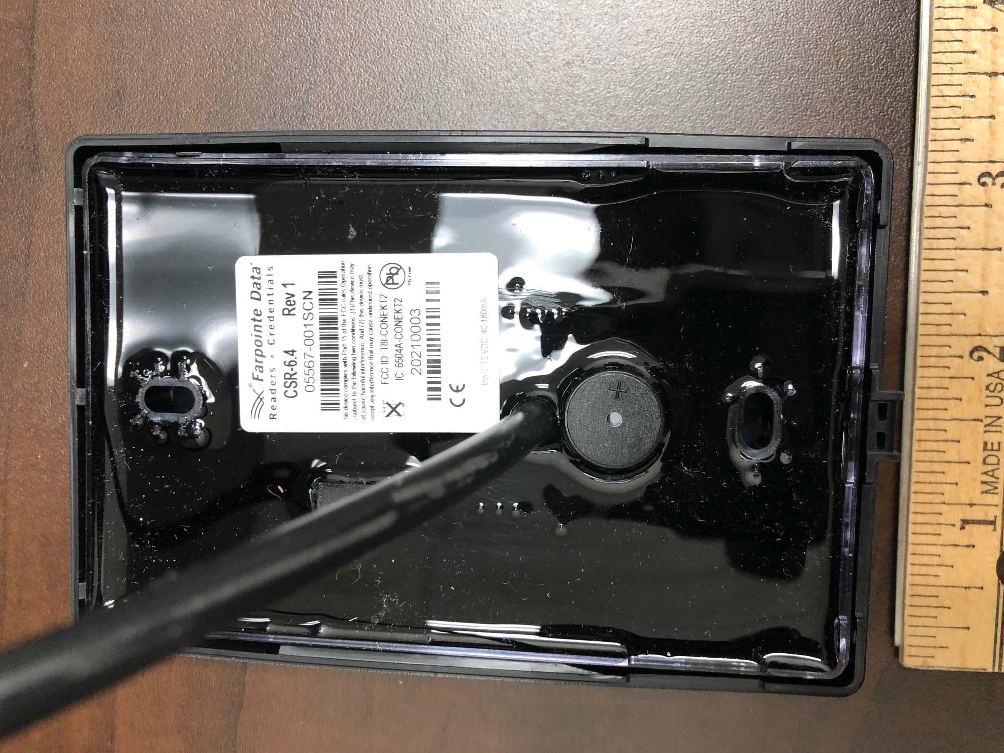
T8I-CONEKT2
Aug 06, 2020CONEKT MOBILE-READY CONTACTLESS SMARTCARD READER
Equipment Class
DXX - Part 15 Low Power Communication Device Transmitter
T8I-CONEKT3
Jul 28, 2020CONEKT MOBILE-READY PROXIMITY READERS
Equipment Class
DXX - Part 15 Low Power Communication Device Transmitter