T9JRN40202.4GHz BLE MODULE
Microchip Technology Inc.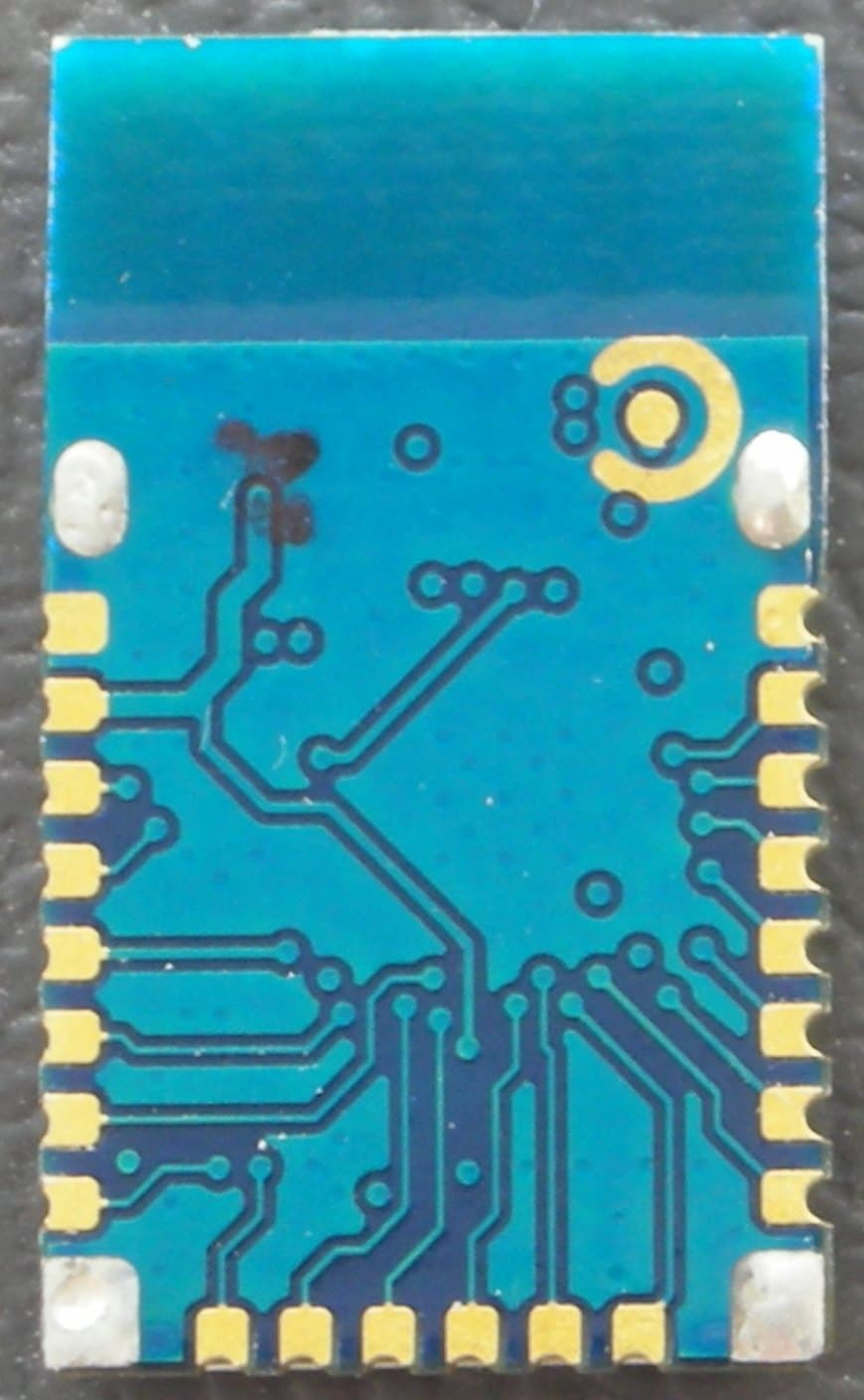
Click to zoom
Application Details
- Equipment Class
- DTS - Digital Transmission System
- Date of Grant
- May 24, 2014
- Application Purpose
- Original Equipment
- Date of Application
- May 17, 2014
- Equipment Note
- 2.4GHz BLE MODULE
- Frequency Range
- 2402.00000000 - 2480.00000000
- Company
- Microchip Technology Inc.
- Country
- United States
Documents & Files
Document Text
Text extracted from the exhibit documents filed with the FCC. Open a document above to read the original.
Users Manual
Microchip RN4020 Certified Bluetooth® Low Energy OEM Module User Guide 1. Introduction Microchip RN4020 Certified Bluetooth Low Energy (BTLE) OEM module is a single mode Bluetooth Smart module that complies with Bluetooth Core Specification 4.0. Through its high speed UART interface, it could be configured to act as either central or peripheral role when establishing connection. It supports 13 public profiles and 18 public services, which are adopted by Bluetooth Special Interest Group (SIG). For all supported profiles and services, RN4020 could be configured to act as server and client roles at the same time. Furthermore, RN4020 supports Microchip private profile Microchip Low Power Data Profile (MLDP) that simulates Serial Port Profile (SPP), which is defined in Bluetooth Classic and enables data stream between two devices. Finally, Microchip RN4020 also supports user self-defined private profile/service, which could precisely fit user’s particular application. All configurations will be saved in onboard no-volatile memory (NVM), so user only needs set up the module once. Microchip RN4020 provides user an easy-to-use, fast-to-market, very flexible and powerful solution for BTLE technology. 2. Fundamental of Bluetooth Low Energy When two BTLE devices want to be connected, one should be in central role and the other in peripheral role. Peripheral would advertise to show its connectable status, while central device will start the connection process. Once connected, either end of connection could choose to bond. Once bonded, all security related key will be saved and security process will be waived when reconnecting. Bonded peripheral device could only perform direct advertise, therefore, no longer to able to connect to device other than its bonded peer. Similar to Bluetooth Classic, BTLE uses the concept of profiles to ensure interoperability between different devices. Unlike Bluetooth Classic, BTLE profiles are collection of services. All BTLE services are built on top of Generic Attribute Profile (GATT), where GATT defines accessibility of attributes called characteristics. The main functionality of BTLE profiles, therefore, is built around the characteristics. For those devices that maintain the value of characteristics in a service, such device is the server of the service. On the other hand, those devices that acquire data from their peer are called client. Each service and its characteristics could be identified by their Universally Unique Identifier (UUID). The UUID could be either short form (16bit) or long form (128bit). All Bluetooth SIG adopted services and characteristics have short UUID, while user self-defined private UUID must be in long form. For the details of Bluetooth SIG adopted services and characteristics, please refer to https://developer.bluetooth.org/gatt/profiles/Pages/ProfilesHome.aspx. The accessibility of each characteristic is defined by 8-bit characteristic property in bitmap format, as shown in table 1. Table 1. Characteristic Properties Property Bitmap Description Extended Property * 0b10000000 Additional property available Authenticated Write * 0b01000000 Write characteristic with authentication from client to server Indicate 0b00100000 Indicate value of characteristic with acknowledgement from server to client Notify 0b00010000 Notify value of characteristic without acknowledgement from server to client Write 0b00001000 Write value of characteristic with acknowledgement from client to server Write without response 0b00000100 Write value of characteristic without acknowledgment from client to server Read 0b00000010 Read value of characteristic. Value is sent from server to client Broadcast 0b00000001 Broadcast value of characteristic * Currently not supported in RN4020 3. Microchip RN4020 OEM Module Control Interface Microchip RN4020 module is fully agent certified Bluetooth Low Energy single mode OEM module. User controls the module through GPIO lines and UART interface. 3.1 RN4020 GPIO Control Lines RN4020 uses 3 input GPIOs to set the module in different states and 3 output GPIOs to indicate current status. GPIO 3 is used to control the operating state of RN4020. When GPIO 3 is put to high, the module wakes up and is set into active mode. Once waking up, “CMD” will be output to the UART and indicate that module is in command mode and ready to take commands from UART. On the other hand, when GPIO 3 is set to be low, the module will exit command mode by output “END” to UART and then operates in deep sleep mode. UART interface will not be responsive in deep sleep mode. When the module is in deep sleep mode, GPIO 9 will output low. GPIO 4 is used to control RN4020 when Microchip private MLDP profile is used. Once get into MLDP mode by setting GPIO 4 at high, all data from UART will be sent to the peer device as data stream. To exit MLDP mode, user needs to put GPIO 4 low, so that module is back to command mode by outputting “CMD” to UART. Setting pin BT_WAKE high is used to wake RN4020 module from dormant mode. When RN4020 module is connected to a peer device, GPIO 5 will output high; otherwise, GPIO 5 outputs low. When in MLDP mode, if RN4020 needs outputting status and/or requesting response from the host MCU, GPIO 6 will be put to high. Once RN4020 exit MLDP mode and getting back to CMD mode, status and/or requests will be output to UART. Once stored data is output to UART, GPIO 6 will be put to low. The maximum buffer of status/requests is 256 bytes. When RN4020 module is in active mode, GPIO 7 will output high; otherwise, GPIO 7 outputs low. 3.2 RN4020 UART Control Interface UART is the main control interface for RN4020. The default UART port configuration for RN4020 is shown in table 2. Table 2: RN4020 UART Configuration Parameter Value Baud Rate 115200 Data Bits 8 Parity None Stop Bits 1 Flow Control None (CTX/RTX in the future) The UART baud rate could be adjusted from 2400 to 932K with command “SB”. Notice that when UART baud rate is set to 2400, …
Text truncated - open the document above for the full version.
Users Manual
2014 Microchip Technology Inc.DSXXXXXXXXA-page 1 RN4020 Features • Fully qualified Bluetooth ® version 4.1 module • Onboard Bluetooth Low Energy 4.1 stack • ASCII command interface API over UART • Multiple IOs for control and status • Secure AES128 encryption • GAP, GATT, SM, L2CAP and integrated public profiles • Create custom services using command API • Microchip Low Energy Data Protocol (MLDP) for streaming data applications • Software configurable role as peripheral or cen- tral, client or server • Compact form factor 11.5 x 19.5 mm • Low-power consumption • UART interface, GPIO, ADC • 64 KB internal serial flash • Castellated SMT pads for easy and reliable PCB mounting • Environmentally friendly, RoHS compliant • Certifications: FCC, IC, CE, QDID • Device Firmware Upgrade (DFU) Description Microchip’s RN4020 Bluetooth Low Energy Module provides a highly integrated solution for delivering low power Bluetooth 4.1 solu tions. The advanced com- mand interface offers rapid time to market. The RN-4020 module complies with Bluetooth specifi- cation version 4.1. It integrates RF, a baseband control- ler, command API processor, making it a compl ete Bluetooth Low Energy Solution. The RN4020 can be used with either low cost micro- controller for intelligent Bluetooth Low Energy applica- tions. For simpl e sensor ap plications, the RN4020 internal scripting capabilities enable basic functions to be implemented without the need for external host MCU or software development tools. Applications • Health/Medical Devices - Glucose Meters - Heart rate -Scale • Sports Activity and Fitness - Pedometer - Cycling computer - Heart rate • Retail -POS - Asset tagging and tracking - Proximity Advertising • Beacon applications • Internet of Things Sensor tag • Remote Control - Keyboard Mice - AV consoles, game controllers • Wearable smart devices and accessories • Industrial Control - Private (custom) services - Low bandwidth cable replacement • Smart Energy/Smart Home Bluetooth ® Low Energy Module DRAFT RN4020 DSXXXXXXXXA-page 2 2014 Microchip Technology Inc. TO OUR VALUED CUSTOMERS It is our intention to provide our valued customers with the best documentation possible to ensure successful use of your Microchip products. To this end, we will continue to improve our publications to better suit your needs. Our publications will be refined and enhanced as new volumes and updates are introduced. If you have any questions or comments regarding this publication, please contact the Marketing Communications Department via E-mail at [email protected]. We welcome your feedback. Most Current Data Sheet To obtain the most up-to-date version of this data sheet, please register at our Worldwide Web site at: http://www.microchip.com You can determine the version of a data sheet by examining its literature number found on the bottom outside corner of any page. The last character of the literature number is the version number, (e.g., DS30000000A is version A of document DS30000000). Errata An errata sheet, describing minor operational differences from the data sheet and recommended workarounds, may exist for current devices. As device/documentation issues become known to us, we will publish an errata sheet. The errata will specify the revision of silicon and revision of document to which it applies. To determine if an errata sheet exists for a particular device, please check with one of the following: • Microchip’s Worldwide Web site; http://www.microchip.com • Your local Microchip sales office (see last page) When contacting a sales office, please specify which device, revision of silicon and data sheet (include literature number) you are using. Customer Notification System Register on our web site at www.microchip.com to receive the most current information on all of our products. Table of Contents 1.0 Device Overview...........................................................................................................................................................................3 2.0 General Specifications..................................................................................................................................................................5 3.0 Microcontroller to RN4020 Interface.............................................................................................................................................6 4.0 Physical Dimensions.....................................................................................................................................................................7 5.0 Typical Application Schematic......................................................................................................................................................8 6.0 ASCII Command API....................................................................................................................................................................9 7.0 Supported Services ....................................................................................................................................................................10 8.0 Regulatory Approval ...................................................................................................................................................................13 9.0 Ordering Information...................................................................................................................................................................19 Appendix A: Revision History...............................................................................................................................................................21 The Microchip Web Site .......................................................................................................................................................................23 Customer Change Notification Service.......................................…
Text truncated - open the document above for the full version.
RF Exposure Info
FCC Part 1 Subpart I FCC Part 2 Subpart J INDUSTRY CANADA RSS 102 ISSUE 4 RF EXPOSURE REPORT FOR 2.4GHz LE MODULE MODEL NUMBER: RN4020 FCC ID: T9JRN4020 IC: 6514A-RN4020 REPORT NUMBER: 14U17191-4, Revision C ISSUE DATE: MAY 16, 2014 Prepared for MICROCHIP TECHNOLOGY INC. 2355 West Chandler Blvd Chandler, AZ 85224-6199, U.S.A. Prepared by UL VERIFICATION SERVICES INC. 47173 BENICIA STREET FREMONT, CA 94538, U.S.A. TEL: (510) 771-1000 FAX: (510) 661-0888 REPORT NO: 14U17191-4C DATE: MAY 16, 2014 FCC ID: T9JRN4020 IC: 6514A-RN4020 Page 2 of 11 UL VERIFICATION SERVICES INC. FORM NO: CCSUP4701I 47173 BENICIA STREET, FREMONT, CA 94538, USA TEL: (510) 771-1000 FAX: (510) 661-0888 This report shall not be reproduced except in full, without the written approval of . UL Verification Services Inc. Revision History Rev. Issue Date Revisions Revised By -- 03/18/14 Initial Issue T. Chan A 05/09/14 Update the separation distance calculation table T. Chan B 05/14/14 Added Statement to clarify SAR exemption M. Mekuria C 05/16/14 Added SAR Exclusion Calculations Table for Portable Devices (separation distance < 20cm) T. Chan REPORT NO: 14U17191-4C DATE: MAY 16, 2014 FCC ID: T9JRN4020 IC: 6514A-RN4020 Page 3 of 11 UL VERIFICATION SERVICES INC. FORM NO: CCSUP4701I 47173 BENICIA STREET, FREMONT, CA 94538, USA TEL: (510) 771-1000 FAX: (510) 661-0888 This report shall not be reproduced except in full, without the written approval of . UL Verification Services Inc. TABLE OF CONTENTS 1. ATTESTATION OF TEST RESULTS ................................................................................. 4 2. TEST METHODOLOGY ..................................................................................................... 5 3. REFERENCES ................................................................................................................... 5 4. FACILITIES AND ACCREDITATION ................................................................................. 5 5. MAXIMUM PERMISSIBLE RF EXPOSURE ....................................................................... 6 5.1. FCC RULES ................................................................................................................ 6 5.2. IC RULES .................................................................................................................... 7 5.3. EQUATIONS ................................................................................................................ 8 5.4. LIMITS AND IC EXEMPTION .....................................................................................10 6. RF EXPOSURE RESULTS ................................................................................................11 REPORT NO: 14U17191-4C DATE: MAY 16, 2014 FCC ID: T9JRN4020 IC: 6514A-RN4020 Page 4 of 11 UL VERIFICATION SERVICES INC. FORM NO: CCSUP4701I 47173 BENICIA STREET, FREMONT, CA 94538, USA TEL: (510) 771-1000 FAX: (510) 661-0888 This report shall not be reproduced except in full, without the written approval of . UL Verification Services Inc. 1. ATTESTATION OF TEST RESULTS COMPANY NAME: MICROCHIP TECHNOLOGY INC – SAN JOSE 2355 WEST CHANDLER BLVD. CHANDLER, AZ 85224-6199, U.S.A. EUT DESCRIPTION: 2.4GHz LE MODULE MODEL: RN4020 SERIAL NUMBER: RN4020-EVB DATE TESTED: MARCH 10 – 11, 2014 APPLICABLE STANDARDS STANDARD TEST RESULTS FCC PART 1 SUBPART I & PART 2 SUBPART J Pass INDUSTRY CANADA RSS 102 ISSUE 4 Pass UL Verification Services Inc. calculated the RF Exposure of the above equipment in accordance with the requirements set forth in the above standards, using test results reported in the test report documents referenced below and/or documentation furnished by the applicant. All indications of Pass/Fail in this report are opinions expressed by UL Verification Services Inc. based on interpretations of these calculations. The results show that the equipment is capable of demonstrating compliance with the requirements as documented in this report. Note: The results documented in this report apply only to the tested sample, under the conditions and modes of operation as described herein. This document may not be altered or revised in any way unless done so by UL Verification Services Inc. and all revisions are duly noted in the revisions section. Any alteration of this document not carried out by UL Verification Services Inc. will constitute fraud and shall nullify the document. This report must not be used by the client to claim product certification, approval, or endorsement by NVLAP, NIST, any agency of the Federal Government, or any agency of any government. Approved & Released For UL Verification Services Inc. By: Tested By: Mengistu Mekuria Roy Zheng Senior Engineer Lab Engineer UL Verification Services Inc. UL Verification Services Inc. REPORT NO: 14U17191-4C DATE: MAY 16, 2014 FCC ID: T9JRN4020 IC: 6514A-RN4020 Page 5 of 11 UL VERIFICATION SERVICES INC. FORM NO: CCSUP4701I 47173 BENICIA STREET, FREMONT, CA 94538, USA TEL: (510) 771-1000 FAX: (510) 661-0888 This report shall not be reproduced except in full, without the written approval of . UL Verification Services Inc. 2. TEST METHODOLOGY All calculations were made in accordance with FCC OET Bulletin 65 Edition 97-01 and IC Safety Code 6. 3. REFERENCES All measurements were made as documented in test report UL Verification Services Inc. Document 14U17191-1 for operation in the 2.4 GHz bands. Output power, Duty cycle and Antenna gain data is excerpted from the applicable test reports. Antenna gain data is excerpted from the applicable test reports. 4. FACILITIES AND ACCREDITATION The test sites and measurement facilities used to collect data are located at 47173 and 47266 Benicia Street, Fremont, California, USA. Line conducted emissions are measured only at the 47173 address. The following table identifies which facilities were utilized for radiated emission measurements documented in this report. Specific facilities are also identified in the test results sections. 47173 Benicia…
Text truncated - open the document above for the full version.
Test Report
FCC 47 CFR PART 15 SUBPART C INDUSTRY CANADA RSS-210 ISSUE 8 BLUETOOTH LOW ENERGY CERTIFICATION TEST REPORT FOR 2.4GHz LE MODULE MODEL NUMBER: RN4020 FCC ID: T9JRN4020 IC: 6514A-RN4020 REPORT NUMBER: 14U17191-1 ISSUE DATE: MARCH 21, 2014 Prepared for MICROCHIP TECHNOLOGY INC. 2355 West Chandler Blvd. Chandler, AZ 85224-6199, U.S.A. Prepared by UL VERIFICATION SERVICES INC. 47173 BENICIA STREET FREMONT, CA 94538, U.S.A. TEL: (510) 771-1000 FAX: (510) 661-0888 REPORT NO: 14U17191-1 DATE: MARCH 21, 2014 FCC ID: T9JRN4020 IC: 6514A-RN4020 Page 2 of 43 UL VERIFICATION SERVICES INC. FORM NO: CCSUP4701I 47173 BENICIA STREET, FREMONT, CA 94538, USA TEL: (510) 771-1000 FAX: (510) 661-0888 This report shall not be reproduced except in full, without the written approval of UL Verification Services Inc. Revision History Rev. Issue Date Revisions Revised By -- 03/21/14 Initial Issue T. Chan REPORT NO: 14U17191-1 DATE: MARCH 21, 2014 FCC ID: T9JRN4020 IC: 6514A-RN4020 Page 3 of 43 UL VERIFICATION SERVICES INC. FORM NO: CCSUP4701I 47173 BENICIA STREET, FREMONT, CA 94538, USA TEL: (510) 771-1000 FAX: (510) 661-0888 This report shall not be reproduced except in full, without the written approval of UL Verification Services Inc. TABLE OF CONTENTS 1. ATTESTATION OF TEST RESULTS ................................................................................. 4 2. TEST METHODOLOGY ..................................................................................................... 5 3. FACILITIES AND ACCREDITATION ................................................................................. 5 4. CALIBRATION AND UNCERTAINTY ................................................................................ 5 4.1. MEASURING INSTRUMENT CALIBRATION .............................................................. 5 4.2. SAMPLE CALCULATION ............................................................................................ 5 4.3. MEASUREMENT UNCERTAINTY ............................................................................... 5 5. EQUIPMENT UNDER TEST ............................................................................................... 6 5.1. DESCRIPTION OF EUT .............................................................................................. 6 5.2. MAXIMUM OUTPUT POWER...................................................................................... 6 5.3. DESCRIPTION OF AVAILABLE ANTENNAS .............................................................. 6 5.4. SOFTWARE AND FIRMWARE .................................................................................... 6 5.5. WORST-CASE CONFIGURATION AND MODE .......................................................... 6 5.6. DESCRIPTION OF TEST SETUP ................................................................................ 7 6. TEST AND MEASUREMENT EQUIPMENT ....................................................................... 9 7. ANTENNA PORT TEST RESULTS ...................................................................................10 7.1. MEASUREMENT METHODS .....................................................................................10 7.2. 6 dB BANDWIDTH ......................................................................................................11 7.3. 99% BANDWIDTH ......................................................................................................14 7.4. OUTPUT POWER.......................................................................................................17 7.5. AVERAGE POWER ....................................................................................................20 7.6. POWER SPECTRAL DENSITY ..................................................................................21 7.7. CONDUCTED SPURIOUS EMISSIONS .....................................................................24 8. RADIATED TEST RESULTS .............................................................................................28 8.1. LIMITS AND PROCEDURE ........................................................................................28 8.2. TX ABOVE 1 GHz FOR BLE MODE IN THE 2.4 GHz BAND ......................................29 8.3. TRANSMITTER ABOVE 1 GHz ..................................................................................33 8.4. WORST-CASE BELOW 1 GHz ...................................................................................39 9. SETUP PHOTOS ...............................................................................................................41 REPORT NO: 14U17191-1 DATE: MARCH 21, 2014 FCC ID: T9JRN4020 IC: 6514A-RN4020 Page 4 of 43 UL VERIFICATION SERVICES INC. FORM NO: CCSUP4701I 47173 BENICIA STREET, FREMONT, CA 94538, USA TEL: (510) 771-1000 FAX: (510) 661-0888 This report shall not be reproduced except in full, without the written approval of UL Verification Services Inc. 1. ATTESTATION OF TEST RESULTS COMPANY NAME: MICROCHIP TECHNOLOGY INC. 2355 West Chandler Blvd. Chandler, AZ 85224-6199, U.S.A. EUT DESCRIPTION: 2.4GHz LE MODULE MODEL: RN4020 SERIAL NUMBER: RN4020-EVB DATE TESTED: MARCH 10 – 11, 2014 APPLICABLE STANDARDS STANDARD TEST RESULTS CFR 47 Part 15 Subpart C Pass INDUSTRY CANADA RSS-210 Issue 8 Annex 8 Pass INDUSTRY CANADA RSS-GEN Issue 3 Pass UL Verification Services Inc. tested the above equipment in accordance with the requirements set forth in the above standards. All indications of Pass/Fail in this report are opinions expressed by UL Verification Services Inc. based on interpretations and/or observations of test results. Measurement Uncertainties were not taken into account and are published for informational purposes only. The test results show that the equipment tested is capable of demonstrating compliance with the requirements as documented in this report. Note: The results documented in this report apply only to the tested sample, under the conditions and modes of operation as described herein. This document ma…
Text truncated - open the document above for the full version.
Test Setup Photos
REPORT NO: 14U17191-1 DATE: MARCH 21, 2014 FCC ID: T9JRN4020 IC: 6514A-RN4020 Page 41 of 43 UL VERIFICATION SERVICES INC. FORM NO: CCSUP4701I 47173 BENICIA STREET, FREMONT, CA 94538, USA TEL: (510) 771-1000 FAX: (510) 661-0888 This report shall not be reproduced except in full, without the written approval of UL Verification Services Inc. 9. SETUP PHOTOS ANTENNA PORT CONDUCTED RF MEASUREMENT SETUP RADIATED RF MEASUREMENT SETUP (ABOVE 1 GHz) ANTENNA PORT CONDUCTED PHOTO X-POSITION REPORT NO: 14U17191-1 DATE: MARCH 21, 2014 FCC ID: T9JRN4020 IC: 6514A-RN4020 Page 42 of 43 UL VERIFICATION SERVICES INC. FORM NO: CCSUP4701I 47173 BENICIA STREET, FREMONT, CA 94538, USA TEL: (510) 771-1000 FAX: (510) 661-0888 This report shall not be reproduced except in full, without the written approval of UL Verification Services Inc. Y-POSITION Z-POSITION REPORT NO: 14U17191-1 DATE: MARCH 21, 2014 FCC ID: T9JRN4020 IC: 6514A-RN4020 Page 43 of 43 UL VERIFICATION SERVICES INC. FORM NO: CCSUP4701I 47173 BENICIA STREET, FREMONT, CA 94538, USA TEL: (510) 771-1000 FAX: (510) 661-0888 This report shall not be reproduced except in full, without the written approval of UL Verification Services Inc. RADIATED RF MEASUREMENT SETUP (BELOW 1 GHz) END OF REPORT RADIATED FRONT PHOTO (BELOW 1 GHz) RADIATED BACK PHOTO (BELOW 1 GHz)
Contact Information
Applicant
Steve Caldwell
Test Firm
UL Verification Services Inc. (formerly UL CCS)Jay Kogoma
Technical Specifications
| # | Rule Parts | Frequency Range | Power Output |
|---|---|---|---|
| 1 | 15C | 2.40 GHz - 2.48 GHz | 7.00 mW |
Other Applications from Microchip Technology Inc.
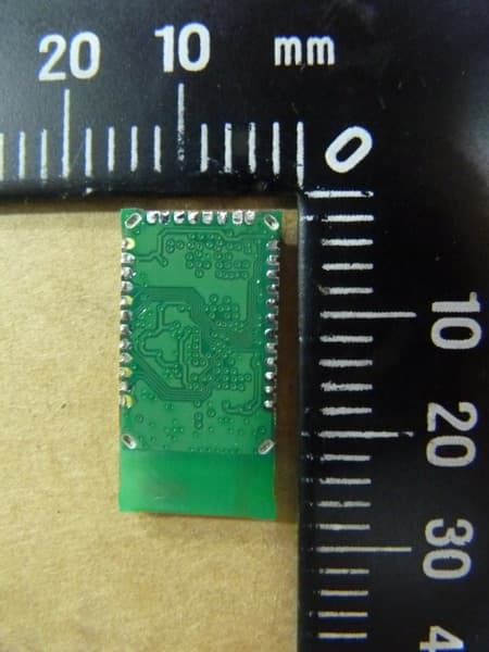
T9JRN41-3
May 28, 2013Class 1 Bluetooth Module
Equipment Class
DSS - Part 15 Spread Spectrum Transmitter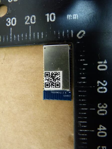
T9J-RN52
Apr 10, 2013Class 2 Bluetooth Module
Equipment Class
DSS - Part 15 Spread Spectrum Transmitter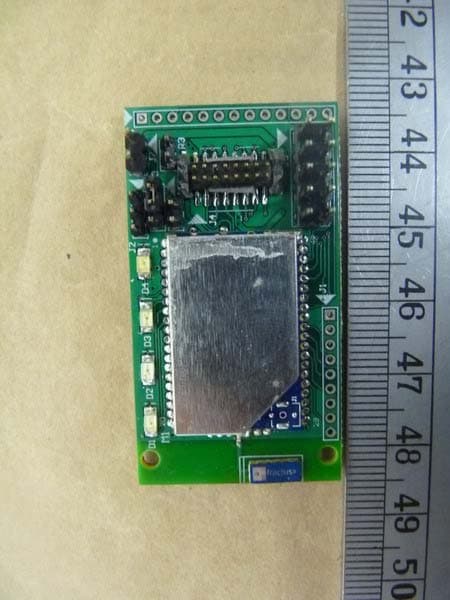
T9J-RN171
Mar 19, 2011WIFLY
Equipment Class
DTS - Digital Transmission System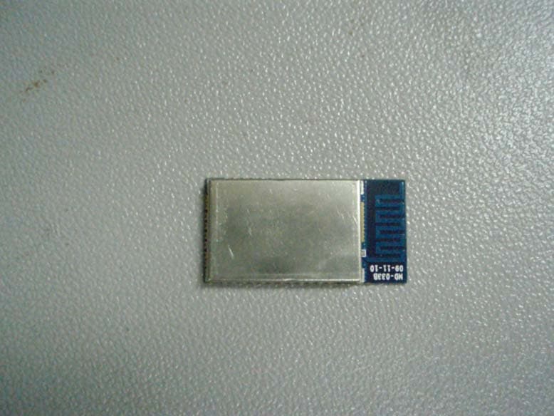
T9J-RN42
Apr 15, 2010RN-42
Equipment Class
DSS - Part 15 Spread Spectrum TransmitterT9J-RN24
Mar 22, 2009Bluetooth Module
Equipment Class
DSS - Part 15 Spread Spectrum Transmitter