TA8AKRC11819-3WCDMA Base station transceiver
Ericsson AB
Click to zoom
Application Details
- Equipment Class
- PCB - PCS Licensed Transmitter
- Date of Grant
- Apr 03, 2008
- Application Purpose
- Original Equipment
- Date of Application
- Apr 03, 2008
- Equipment Note
- WCDMA Base station transceiver
- Frequency Range
- 1932.40000000 - 1987.60000000
- Company
- Ericsson AB
- Country
- Sweden
Documents & Files
Document Text
Text extracted from the exhibit documents filed with the FCC. Open a document above to read the original.
Cover Letter(s)
Ericsson Internal EXHIBIT 13 1 (1) Prepared (also subject responsible if other) No. EAB/FJB/SC Christer Gustavsson Approved Checked Date Rev Reference KI/EAB/FJB/SC Christer Gustavsson 2008-04-01 B TA8AKRC11819-3 Federal Communications Commission Authorization & Evaluation Division 7435 Oakland Mills Road Columbia, Maryland 21046 Attention: Equipment Authorization Branch SP Technical Research Institute of Sweden Brinellgatan 4 Box 857 S-501 15 Borås Sweden February 7, 2008 Subject: Certification for FCC ID: TA8AKRC11819-3 To Whom It May Concern: Ericsson AB requests a Grant of Certification (Type Acceptance) for the above mentioned FCC Identifier. This base station transceiver (Radio Unit – RU) is designed for use in the WCDMA 1900 MHz cellular telephone system. The transmitter will operate from1932.4 to 1987.6 MHz with 4.17 MHz Bandwidth. The receiver circuit supports 1852.4 to 1907.6 MHz. The base station operates in the 1900 MHz broadband PCS services as per 47 CFR Part 24 subpart E. It meets the requirements of 3GPP specification for operation in WCDMA cellular systems. This base station transceiver (RU) will in single carrier mode operate at a nominal power out of 40 watts at the output connector and in multi carrier mode where the unit will operate at a nominal power out of 20 watts per carrier at the output connector. Ericsson AB requests confidentiality under CFR 0.459 according to attached letter. We further certify that the applicant nor any party to the application is subject to a denial of Federal benefits, that includes FCC benefits, pursuant to section 5301 of the Anti-Drug abuse Act of 1988, 21 U.S.C. Section 862. Ericsson AB accept by this request the agreement set out in the document "Bilaga SPCR 125 -Avtal om marknadskontroll för radioutrustning certifierad för USA-marknaden". If additional information is needed, please contact me on the below listed number. Regards, Christer Gustavsson Staff Engineer, Regulatory Programs Ericsson AB FCC Registration Number (FRN): 0013476155 Torshamnsgatan 21-23 (Färögatan 6) Kista, SE-164 80 Stockholm Sweden Telephone No.: +46 8 757 59 49 Fax No.: +46 8 404 44 20 e-mail [email protected]
Cover Letter(s)
Ericsson Internal EXHIBIT 13 1 (1) Prepared (also subject responsible if other) No. EAB/FJB/SC Christer Gustavsson Approved Checked Date Rev Reference KI/EAB/FJB/SC Christer Gustavsson 2008-02-07 A TA8AKRC11819-3 Federal Communications Commission Authorization & Evaluation Division 7435 Oakland Mills Road Columbia, Maryland 21046 Attention: Equipment Authorization Branch SP Technical Research Institute of Sweden Brinellgatan 4 Box 857 S-501 15 Borås Sweden February 7, 2008 Subject: Request for Confidentiality To Whom It May Concern: We, Ericsson AB, hereby request that the Exhibits/Items listed below be withheld from public inspection in accordance with Sections 0.457 and 0.459 of the Commission’s Rules. This due to the following reasons: DS-CDMA Base Stations (BS) are designed strictly based on the technical specifications of the international project 3GPP (the 3 rd Generation Partnership Project). The competition in this field is very intense and a less advanced solution/design could get an unfair advantage by accessing the information as listed below from common domain. As we believe that we have implemented groundbreaking solutions and designs into our recent BS/Radio Unit (RU) compared to the previous BS/RU, the listed Exhibits/Items need to be protected from disclosure to our competitors in the industry. As the FCC records have in-depth information and a very wide distribution, we believe that you can understand our concerns. We are strong in our belief that all vendors in the industry need to compete by their own merits. We regard these Exhibits/Items to be our intellectual property and therefore as confidential information. As out BS are generally installed in restricted places, public access is not possible all thought some types of our BS under certain circumstances can be installed in an unrestricted place, but the doors on all of our BS’s are key-locked and can be opened only by authorized personnel. It is therefore individual modules within our BS that should not be revealed to the public. There are advanced technical and design solutions/information in the Exhibits/Items, as mentioned above, that we regard as Ericsson proprietary, with actual and potential patents pending. The information can be advantageous to our competitors as well as sources seeking ways to hack past the built in security functionality. These solutions or information thereof are not accessible even for our customers or partners unless non-disclosure agreements for particular item(s) have been signed. Confidential product information can be found in, but not necessarily limited to, internal photos of the BS and the RU, block diagrams, schematics diagrams, and parts lists as well as certain documents, such as the user’s manuals. Those documents can only be accessible by the customers who purchase out BS and accept the conditions and therefore are provided with unique information access tools. EXHIBIT 9 Internal Photos of Radio Unit EXHIBIT 4 Block Diagrams EXHIBIT 5 Schematic Diagrams EXHIBIT 8 Manuals EXHIBIT 10 Parts List EXHIBIT 12 Technical Circuit Description If additional information is needed, please contact me on the below listed number. Regards, Christer Gustavsson Staff Engineer, Regulatory Programs Ericsson AB FCC Registration Number (FRN): 0013476155 Torshamnsgatan 21-23 (Färögatan 6) Kista, SE-164 80 Stockholm Sweden Telephone No.: +46 8 757 59 49 Fax No.: +46 8 404 44 20 e-mail [email protected]
Cover Letter(s)
Ericsson Internal EXHIBIT 13 1 (1) Prepared (also subject responsible if other) No. EAB/FJB/SCRGD Christer Gustavsson Approved Checked Date Rev Reference KI/EAB/FJB/SC Christer Gustavsson 2008-02-07 A TA8AKRC11819-3 Federal Communications Commission Authorization & Evaluation Division 7435 Oakland Mills Road Columbia, Maryland 21046 Attention: Equipment Authorization Branch SP Technical Research Institute of Sweden Brinellgatan 4 Box 857 S-501 15 Borås Sweden February 7, 2008 Subject: Modem in Filter Unit for the Radio Unit with FCC ID: TA8AKRC11819-3 To Whom It May Concern: Enclosed are requests of a Grant of Certification (Type Acceptance) for the above-mentioned FCC Identifier from Ericsson AB. The Cavity Filter Unit KRC 118 20/1 used for band pass filtering of the transmit signal from KRC 118 19/3 with the above FCC Identifier has a FSK/OOK modem. This modem is not activated, the intention is to use it for signaling to mast mounted equipment in the future. This function will be treated as a permissible change when it is time for use of this function. If additional information is needed, please contact me on the below listed number. Regards, Christer Gustavsson Staff Engineer, Regulatory Programs Ericsson AB FCC Registration Number (FRN): 0013476155 Torshamnsgatan 21-23 (Färögatan 6) Kista, SE-164 80 Stockholm Sweden Telephone No.: +46 8 757 59 49 Fax No.: +46 8 404 44 20 e-mail [email protected]
Cover Letter(s)
Ericsson Internal EXHIBIT 13 1 (1) Prepared (also subject responsible if other) No. EAB/FJB/SC Christer Gustavsson Approved Checked Date Rev Reference KI/EAB/FJB/SC Christer Gustavsson 2008-02-07 A TA8AKRC118§9-3 Federal Communications Commission Authorization & Evaluation Division 7435 Oakland Mills Road Columbia, Maryland 21046 Attention: Equipment Authorization Branch SP Technical Research Institute of Sweden Brinellgatan 4 Box 857 S-501 15 Borås Sweden February 7, 2008 Subject: Temperature Range Information for Certification for FCC ID: TA8AKRC11819-3 To Whom It May Concern: Enclosed are requests of a Grant of Certification (Type Acceptance) for the above-mentioned FCC Identifier from Ericsson AB. The Temperature Range for this base station transceiver (Radio Unit – RU) are designed together with the cabinet and other boards for use in a temperature range of 0º C to +50º C. The base station transceiver (RU) is equipped with a thermal sensor that shut down the exciter power amplifier in the RU in a controlled way at temperatures below -2º C and above + 52º C. The frequency stabilizing circuitry and the power amplifier are still in stand-by mode below and above these temperatures to be prepared to transmit with proper function if the environment temperature reaches the applicable temperature range again. There is also a non- destruction temperature range outside the range above where the base station is shut down totally. If additional information is needed, please contact me on the below listed number. Regards, Christer Gustavsson Staff Engineer, Regulatory Programs Ericsson AB FCC Registration Number (FRN): 0013476155 Torshamnsgatan 21-23 (Färögatan 6) Kista, SE-164 80 Stockholm Sweden Telephone No.: +46 8 757 59 49 Fax No.: +46 8 404 44 20 e-mail [email protected]
External Photos
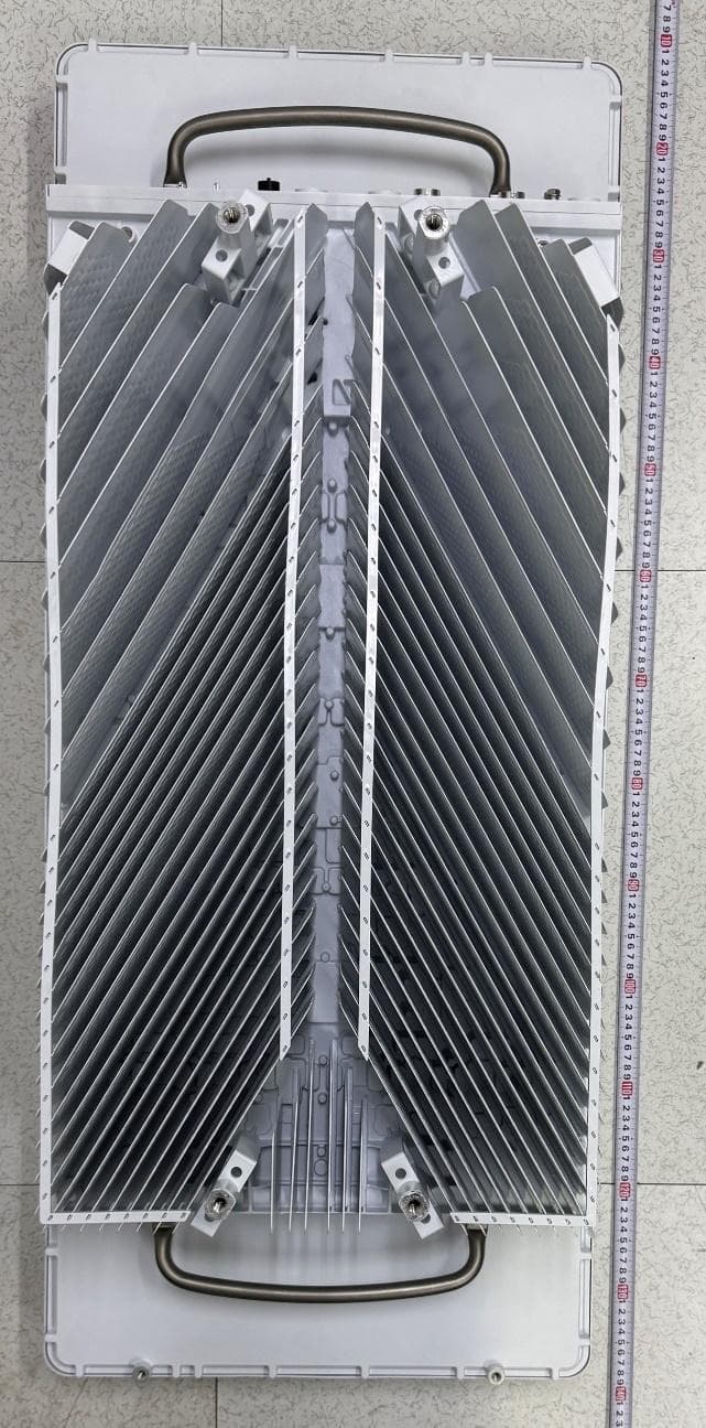
Date Page KRC 118 19/3 R2A 2008-03-05 1(2) External photos Front side Rear side Date Page KRC 118 19/3 R2A 2008-03-05 2(2) External photos Left side Right side
ID Label/Location Info
Date Page KRC 118 19/3 R2A 2008-03-05 1(1) FCC ID FCC ID label and placement
Test Report
Date Reference Page REPORT 2008-03-19 F800029-F24 2 (2) FCC ID: TA8AKRC11819-3 Table of contents Description of the test object Appendix 1 Operation mode during measurements Appendix 1 Test setups Appendix 1 Purpose of test Appendix 1 RF power output Appendix 2 Occupied bandwidth Appendix 3 Band edge Appendix 4 Spurious emission at antenna terminals Appendix 5 Field strength of spurious radiation Appendix 6 Frequency stability Appendix 7 External photos Appendix 8 Date Reference Page REPORT 2008-03-19 F800029-F24 1 (5) FCC ID: TA8AKRC11819-3 Appendix 1 Description – Test object Equipment: WCDMA Transceiver unit (RU) 1900 MHz, single and multi carrier. Tx Frequency range: 1932.4-1987.6 MHz Modulations: QPSK and 16QAM Maximum output power: Single carrier: 1x 46 dBm (40W) Multi carrier: 2x 43 dBm (20W) Nominal power voltage: -48 VDC Tested channels UARFCN Frequency 9662 1932.4 MHz 9712 1942.4 MHz 9763 1952.4 MHz 9788 1957.6 MHz 9813 1962.4 MHz 9888 1977.6 MHz 9938 1987.6 MHz Operation mode during measurements Test models All measurements were performed with the test object transmitting the Test models 1 and 5 defined in 3GPP TS 25.141. Test model 1 uses the QPSK modulation only, and Test model 5 includes the 16QAM modulation. Conducted measurements All RF conducted measurements were done at the output connector (Ant A) of the Filter Unit (FU) KRC 118 20/1. The measurements were performed at maximum output power with both modulations. The test object was powered with -48 VDC during the measurements. The settings below was found to be representative for all traffic scenarios when several settings were tested to find the setting for worst case. Single carrier Test model 1: 64 DPCH:s at 30 ksps (SF=128) Test model 5: 30 DPCH:s at 30 ksps (SF=128) and 8 HS-PDSCH:s at 240 ksps (SF=16) Multi carrier Test model 1: 32 DPCH:s at 30 ksps (SF=128) Test model 5: 30 DPCH:s at 30 ksps (SF=128) and 8 HS-PDSCH:s at 240 ksps (SF=16) Date Reference Page REPORT 2008-03-19 F800029-F24 2 (5) FCC ID: TA8AKRC11819-3 Appendix 1 Radiated measurements All radiated measurements were performed with the test object installed in a wooden rack without EMC shielding. This configuration represents worst case for radiated spurious emission measurements. The test object was powered with -48 VDC. The RU unit was activated for maximum transmit power. The RU unit was activated as Single Carrier (1x46dBm) and Multi Carrier (2x43 dBm). The RF output power port was terminated with 50 ohm loads. The settings below were found to be representative for all traffic scenarios when several settings were tested to find the setting for worst case. The RU unit were allocated to the following UARFCN: Single Carrier: Modulation QPSK 16QAM QPSK 16QAM QPSK 16QAM Downlink UARFCN 9662 (1932.4 MHz) 9662 (1932.4 MHz) 9787 (1957.6 MHz) 9787 (1957.6 MHz) 9938 (1987.6 MHz) 9938 (1987.6 MHz) Uplink UARFCN 9262 (1852.4 MHz) 9262 (1852.4 MHz) 9387 (1877.4 MHz) 9387 (1877.4 MHz) 9538 (1907.6 MHz) 9538 (1907.6 MHz) Test model 1 5 1 5 1 5 Test model 1: 64 DPCH:s at 30 ksps (SF=128) Test model 5: 30 DPCH:s at 30 ksps (SF=128) and 8 HS-PDSCH:s at 240 ksps (SF=16) Multi Carrier: Cell 1 2 Modulation QPSK 16QAM Downlink 9662 (1932.4 MHz) 9712 (1942.4 MHz) Uplink 9262 (1852.4 MHz) 9312 (1862.4 MHz) Test model 1 5 Test model 1: 32 DPCH:s at 30 ksps (SF=128) Test model 5: 30 DPCH:s at 30 ksps (SF=128) and 8 HS-PDSCH:s at 240 ksps (SF=16) Purpose of test The purpose of the tests is to verify compliance to the performance characteristics specified in applicable items of FCC CFR 47. References Measurements were done according to relevant parts of the following standards: ANSI 63.4-2003 ANSI/TIA/EIA-603-B-2002 3GPP TS 25.141 Date Reference Page REPORT 2008-03-19 F800029-F24 3 (5) FCC ID: TA8AKRC11819-3 Appendix 1 Reservation The test results in this report apply only to the particular test object as declared in the report. Delivery of test object The test object was delivered: 2008-02-11 Manufacturer’s representative Christer Gustavsson, Ericsson AB. Test engineers Jonas Bremholt and Jörgen Wassholm Test witnesses Christer Gustavsson and Gunnar Svensson, Ericsson AB. Date Reference Page REPORT 2008-03-19 F800029-F24 4 (5) FCC ID: TA8AKRC11819-3 Appendix 1 Test set-up, conducted measurements 1. Test object, RU KRC 118 19/3 Rev. R2A, Serial No: AB20303776 (FCC ID: TA8AKRC11819-3) 2. FU KRC 118 20/1 Rev. R1H, Serial No: A400578052 Functional test equipment 3. BB subrack with software CXP 901 2073-R5M06 4. RNC: Mini-sim #33 4780 DA BAMS-1000117285 (Iub transmission configured as T1) 5. Switch, Netgear Ethernet switch DS108 6. Computer: SunBlade 2500 (IOV S4) 7. Wooden rack 8. Attenuator The test object was hosted in a RBS 3206M during the frequency error measurements. Date Reference Page REPORT 2008-03-19 F800029-F24 5 (5) FCC ID: TA8AKRC11819-3 Appendix 1 Test set-up, radiated measurements Note: The Mub cable were not attached during the measurements, only used to activate/ deactivate the transmitter. Test object 1. Test object, RU KRC 118 19/3 Rev. R2A, Serial No: AB20303776 (FCC ID: TA8AKRC11819-3) 2. FU KRC 118 20/1 Rev. R1H, Serial No: A400578052 Functional test equipment 3. BB subrack with software CXP901 2073/1 rev R5M06 4. RNC: Mini-sim #51 4780 DA S/N 0205 (Iub transmission configured as T1) 5. Switch, Procurve 2810-24G, BAMS1000552539 6. Computer: SunBlade 2500 BAMS0000015232 7. Wooden rack 8. Terminator (50 ohn) 9. Non conductive table Date Reference Page REPORT 2008-03-19 F800029-F24 1 (1) FCC ID: TA8AKRC11819-3 Appendix 2 RF power output measurements according to 47 CFR 2.1046 Date 2008-02-13 2008-02-14 Temperature 23 °C ± 3 °C 23 °C ± 3 °C Humidity 25 % ± 5 % 14 % ± 5 % Test set-up and procedure The output was connected to a peak power analyzer. The transmitter was set up according to Test model 1 and Test model 5 during the measurements. Measurement equipment Calibration Due SP number Boonton RF Peak power meter/analyzer 2008-12 503 144 Boonton Power sensor 5…
Text truncated - open the document above for the full version.
Contact Information
Applicant
Peter Moberg(Head of PEU Radio)
Technical Contact
Ericsson ABChrister Gustavsson
[email protected]+46 8 757 59 49
Torshamnsgatan 21-23 · Stockholm · Sweden
Test Firm
RISE Research Institutes of Sweden ABDaniel Lundgren
[email protected]+46 10 516 5836
Technical Specifications
| # | Rule Parts | Frequency Range | Power Output | Emission | Tolerance |
|---|---|---|---|---|---|
| 1 | 24E | 1.93 GHz - 1.99 GHz | 40 W | 4M17F9W | 0.0500000000 ppm |
Other Applications from Ericsson AB
TA8BKRD901316
Sep 02, 2026Multi-standard remote radio
Equipment Class
PCB - PCS Licensed Transmitter
TA8BKRY901523
Jul 23, 2026Radio Unit
Equipment Class
PCB - PCS Licensed Transmitter
TA8BKRY901515
Jul 23, 2026Radio Unit
Equipment Class
TNB - Licensed Non-Broadcast Station Transmitter
TA8BKRY901551
Jul 06, 2026Radio Unit
Equipment Class
TNB - Licensed Non-Broadcast Station Transmitter
TA8AKRD901316
Jun 29, 2026Multi-standard remote radio
Equipment Class
PCB - PCS Licensed Transmitter