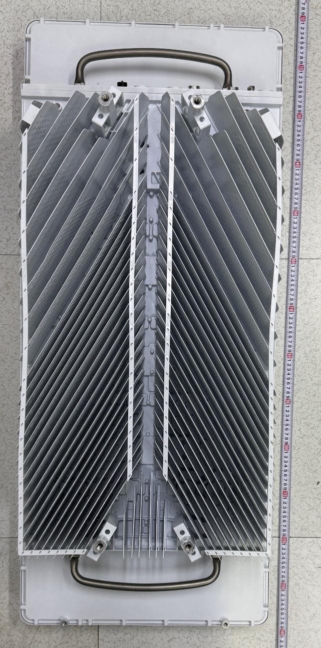
TA8BKRY901515Radio Unit
Ericsson AB
Click to zoom
Application Details
- Equipment Class
- TNB - Licensed Non-Broadcast Station Transmitter
- Date of Grant
- Jul 23, 2026
- Application Purpose
- Original Equipment
- Equipment Note
- Radio Unit
- Frequency Range
- 3705.00000000 - 3975.00000000
- Company
- Ericsson AB
- Country
- Sweden
Documents & Files
Document Text
Text extracted from the exhibit documents filed with the FCC. Open a document above to read the original.
ID Label/Location Info
Ericsson Canada Confidential Exhibit 01 - ID Label Legal Overlay for Dot 4469 B77D (KRY 901 515/2) - The text printed shall be: FCC ID: TA8BKRY901515 IC: 287AB-BS901523 IC MODEL NO: BS9015152 For indoor use only in Canada
Test Setup Photos
Section 3: Equipment under test (EUT) details Report ID: REP169666 Page 13 of 203 3.5 Setup photographs Figure 3.5-1: Set up photo for Conducted Radio Compliance Testing Figure 3.5-2: Set up photo for Conducted Radio Compliance Testing (thermal) Section 3: Equipment under test (EUT) details Report ID: REP169666 Page 14 of 203 Setup photographs, continued Figure 3.5-3: EUT Set-up photo for Radiated Emissions [30 MHz to 1000 MHz] Figure 3.5-4: EUT Set-up photo for Radiated Emissions [30 MHz to 1000 MHz] Section 3: Equipment under test (EUT) details Report ID: REP169666 Page 15 of 203 Setup photographs, continued Figure 3.5-5: EUT Set-up photo for Radiated Emissions [1-6 GHz] Figure 3.5-6: EUT Set-up photo for Radiated Emissions [6-18 GHz] Section 3: Equipment under test (EUT) details Report ID: REP169666 Page 16 of 203 Setup photographs, continued Figure 3.5-7: EUT Set-up photo for Radiated Emissions [18-40 GHz] Figure 3.5-8: EUT Set-up photo for Radiated Emissions [18-40 GHz]
Test Report
Section 8 Testing data Test name Radiated Spurious emissions Specification FCC 47 CFR Part 27, ISED RSS-Gen, RSS-192, RSS-198, RSS-133, RSS-139 Report ID: REP169666R2 Page 178 of 202 Test data, continued Figure 8.9-6: Radiated spurious emissions within 1–6 GHz, [B77D_Single carrier operation] Figure 8.9-7: Radiated spurious emissions within 1–6 GHz, [B77D_Multi carrier, Non-contiguous operation] 5 Figure 8.9-8: Radiated spurious emissions within 1–6 GHz, [B25_Single carrier operation] Figure 8.9-9: Radiated spurious emissions within 1–6 GHz, [B66_Multi carrier, Non-contiguous operation] Figure 8.9-10: Radiated spurious emissions within 1-6 GHz MHz, [Multi carrier, Non- Contiguous Channel] - Worst case comparison plot for model variant according to KDB 484596 D01 Referencing Test Data 0 10 20 30 40 50 60 70 80 90 1G 2G 3G 4G 5G 6G Level in dBμV/m Frequency in Hz RE 1-6 GHz scan [Dot 4465 B77D_Config 1] PK+_MAXH -33 dBm to 62.23 Intentional Tx 0 10 20 30 40 50 60 70 80 90 1G 2G 3G 4G 5G 6G Level in dBμV/m Frequency in Hz RE 1-6 GHz scan [Dot 4465 B77D_Config 2] PK+_MAXH -33 dBm to 62.23 Intentional Tx 0 10 20 30 40 50 60 70 80 1G 2G 3G 4G 5G 6G Level in dBμV/m Frequency in Hz RE 1-6 GHz scan [Dot 4465 B25_Config 1]_SC -16 dBm to 79.23 dBuV/m PK+_MAXH Intentional Tx 0 10 20 30 40 50 60 70 80 90 1G 2G 3G 4G 5G 6G Level in dBμV/m Frequency RE 1-6 GHz scan [Dot 4455 B66_Config 2] -16 dBm to 79.23 dBuV/m PK+_MAXH Intentional Tx 0 5 10 15 20 25 30 35 40 45 50 55 60 65 70 1G2G3G4G5G6G Level in dBμV/m Frequency in Hz RE 1-6 GHz scan [Dot 4455 B77D] AVG_MAXH PK+_MAXH -33 dBm to 62.23 Intentional Tx Section 8 Testing data Test name Radiated Spurious emissions Specification FCC 47 CFR Part 27, ISED RSS-Gen, RSS-192, RSS-198, RSS-133, RSS-139 Report ID: REP169666R2 Page 179 of 202 Test data, continued Figure 8.9-11: Radiated spurious emissions within 6–18 GHz, [B77D_Single carrier operation] Figure 8.9-12: Radiated spurious emissions within 6–18 GHz, [B77D_Multi carrier, Non-contiguous operation] Figure 8.9-13: Radiated spurious emissions within 6–18 GHz, [B25_Single carrier operation] Figure 8.9-14: Radiated spurious emissions within 6–18 GHz, [B66_Multi carrier, Non-contiguous operation] Figure 8.9-15: Radiated spurious emissions within 6-18 GHz MHz, [Multi carrier, Non- Contiguous Channel] - Worst case comparison plot for model variant according to KDB 484596 D01 Referencing Test Data 40 45 50 55 60 65 70 6G 8 9 10G 18G Level in dBμV/m Frequency in Hz RE 6-18 GHz scan [Dot 4465 B77D_Config 1]_SC PK+_MAXH MaxPeak-PK+ (Single) -33 dBm to 62.23 dBuV CAverage-CAV (Single) 40 42 44 46 48 50 52 54 56 58 60 62 64 66 68 70 6G 8 9 10G 18G Level in dBμV/m Frequency in Hz RE 6-18 GHz scan [Dot 4465 B77G_Config 2]_NC PK+_MAXH -30 dBm to 65.23 dBuV MaxPeak-PK+ (Single) CAverage-CAV (Single) 40 45 50 55 60 65 70 75 80 6G 8 9 10G 18G Level in dBμV/m Frequency in Hz RE 6-18 GHz scan [Dot 4455 B25_Confi g 1] PK+_MAXH -16 dBm to 79.23 dBuV 40 45 50 55 60 65 70 75 80 6G 8 9 10G 18G Level in dBμV/m Frequency in Hz RE 6-18 GHz scan [Dot 4465 B66_Confi g 2]_N C PK+_MAXH -16 dBm to 79.23 dBuV 40 45 50 55 60 65 70 6G 8 9 10G 18G Level in dBμV/m Frequency RE 6-18 GHz scan [Dot 4455 B77D] -33 dBm to 62.23 dBuV/m PK+_MAXH MaxPeak-PK+ (Single) -33 dBm to 62.23 dBuV CAverage-CAV (Single) Section 8 Testing data Test name Radiated Spurious emissions Specification FCC 47 CFR Part 27, ISED RSS-Gen, RSS-192, RSS-198, RSS-133, RSS-139 Report ID: REP169666R2 Page 180 of 202 Test data, continued Figure 8.9-16: Radiated spurious emissions within 18–40 GHz, [B77D_Single carrier operation] Figure 8.9-17: Radiated spurious emissions within 18–40 GHz, [B77D_Multi carrier, Non-contiguous operation] Figure 8.9-18: Radiated spurious emissions within 18–40 GHz, [B25_Single carrier operation] Figure 8.9-19: Radiated spurious emissions within 18–40 GHz, [B66_Multi carrier, Non-contiguous operation] Figure 8.9-20: Radiated spurious emissions within 18-40 GHz MHz, [Multi carrier, Non- Contiguous Channel] - Worst case comparison plot for model variant according to KDB 484596 D01 Referencing Test Data 10 15 20 25 30 35 40 45 50 55 60 65 70 75 80 18G 30G 40G Level in dBμV/m Frequency in Hz RSE 18-40 GHz scan [Dot 4465 B77D_Config 1]_SC AVG_MAXH PK+_MAXH -27 dBm to 68.23 dBuV MaxPeak-PK+ (Single) CAverage-CAV (Single) 10 15 20 25 30 35 40 45 50 55 60 65 70 75 80 18G 30G 40G Level in dBμV/m Frequency in Hz RSE 18-40 GHz scan [Dot 4465 B77D_Config 2]_NC AVG_MAXH PK+_MAXH -27 dBm to 68.23 dBuV MaxPeak-PK+ (Single) CAverage-CAV (Single) 20 25 30 35 40 45 50 55 60 65 70 75 80 18G 30G 40G Level in dBμV/m Frequency in Hz RSE 18-40 GHz scan [Dot 4465 B25_Config 1]_SC AVG_MAXH PK+_MAXH -16 dBm to 79.23 dBuV/m 20 25 30 35 40 45 50 55 60 65 70 75 80 18G 30G 40G Level in dBμV/m Frequency in Hz RSE 18-40 GHz scan [Dot 4455 B66_Config 2]_NC AVG_MAXH PK+_MAXH -16 dBm to 79.23 dBuV/m 10 15 20 25 30 35 40 45 50 55 60 65 70 75 80 18G 30G 40G Level in dBμV/m Frequency in Hz RSE 18-40 GHz scan [Dot 4455 B77D] AVG_MAXH PK+_MAXH -27 dBm to 68.23 dBuV MaxPeak-PK+ (Single) CAverage-CAV (Single) Section 8 Testing data Test name Frequency stability Specification RSS-133, RSS-139, RSS-192, RSS-198, FCC 27.54, FCC 24.235 Report ID: REP169666R2 Page 181 of 202 8.10 Frequency stability 8.10.1 Definitions and limits FCC §24.235 The frequency stability shall be sufficient to ensure that the fundamental emission stays within the authorized frequency block. FCC §27.54: The frequency stability shall be sufficient to ensure that the fundamental emissions stay within the authorized bands of operation. RSS-198, Section 5.4: The frequency stability shall be sufficient to ensure that the occupied bandwidth stays within the operating frequency block or frequency block group when tested at the temperature and supply voltage variations specified in RSS-Gen. RSS-192, Section 5.4: The frequency stability shall be sufficient to ensure that the occupied bandwidth stays within the operating frequen…
Text truncated - open the document above for the full version.
Test Report
Section 8 Testing data Test name Transmitter unwanted emission (Band 3900-3980 MHz) Specification RSS-198, Issue 1 Report ID: REP169666R2 Page 149 of 202 Test data, continued On the plots below the measured Channel Power value in the “Total Channel Power” column must be −19 dBm and lower. Figure 8.6-128: Conducted emission at the lower band edge Figure 8.6-129: Conducted emission at the upper band edge Frequency: 3900 MHz Mode: Single-carrier operation Frequency: 3980 MHz Mode: Single-carrier operation Meas. BW: 1 MHz Tech.: NR 80 MHz Meas. BW: 1 MHz Tech.: NR 80 MHz Limit: −19 dBm/MHz Notes: None Limit: −19 dBm/MHz Notes: None Section 8 Testing data Test name Transmitter unwanted emission (Band 3900-3980 MHz) Specification RSS-198, Issue 1 Report ID: REP169666R2 Page 150 of 202 Test data, continued On the plots below the measured Channel Power value in the “Total Channel Power” column must be −19 dBm and lower. Figure 8.6-130: Conducted emission at the lower band edge Figure 8.6-131: Conducted emission at the upper frequency block edge of the lower channel Frequency: 3900 MHz Mode: 2-carrier operation Frequency: 3920 MHz Mode: 2-carrier operation Meas. BW: 1 MHz Tech.: NR 10 MHz Meas. BW: 1 MHz Tech.: NR 10 MHz Limit: −19 dBm/MHz Notes: None Limit: −19 dBm/MHz Notes: None Figure 8.6-132: Conducted emission at the upper band edge Figure 8.6-133: Conducted emission at the lower frequency block edge of the upper channel Frequency: 3980 MHz Mode: 2-carrier operation Frequency: 3960 MHz Mode: 2-carrier operation Meas. BW: 1 MHz Tech.: NR 10 MHz Meas. BW: 1 MHz Tech.: NR 10 MHz Limit: −19 dBm/MHz Notes: None Limit: −19 dBm/MHz Notes: None Section 8 Testing data Test name Transmitter unwanted emission (Band 3900-3980 MHz) Specification RSS-198, Issue 1 Report ID: REP169666R2 Page 151 of 202 Test data, continued On the plots below the measured Channel Power value in the “Total Channel Power” column must be −19 dBm and lower. Figure 8.6-134: Conducted emission at the lower band edge Figure 8.6-135: Conducted emission at the upper band edge Frequency: 3900 MHz Mode: 2-carrier operation Frequency: 3980 MHz Mode: 2-carrier operation Meas. BW: 1 MHz Tech.: NR 40 MHz Meas. BW: 1 MHz Tech.: NR 40 MHz Limit: −19 dBm/MHz Notes: None Limit: −19 dBm/MHz Notes: None Section 8 Testing data Test name Transmitter unwanted emission (Band 3900-3980 MHz) Specification RSS-198, Issue 1 Report ID: REP169666R2 Page 152 of 202 Test data, continued On the plots below the measured Channel Power value in the “Total Channel Power” column must be −19 dBm and lower. Figure 8.6-136: Conducted emission at the lower band edge Figure 8.6-137: Conducted emission at the upper frequency block edge of the lower channel Frequency: 3900 MHz Mode: 6-carrier operation Frequency: 3960 MHz Mode: 6-carrier operation Meas. BW: 1 MHz Tech.: NR 10 MHz Meas. BW: 1 MHz Tech.: NR 10 MHz Limit: −19 dBm/MHz Notes: None Limit: −19 dBm/MHz Notes: None Figure 8.6-138: Conducted emission at the upper band edge Figure 8.6-139: Conducted emission at the lower frequency block edge of the top channel Frequency: 3980 MHz Mode: 6-carrier operation Frequency: 3920 MHz Mode: 6-carrier operation Meas. BW: 1 MHz Tech.: NR 10 MHz Meas. BW: 1 MHz Tech.: NR 10 MHz Limit: −19 dBm/MHz Notes: None Limit: −19 dBm/MHz Notes: None Section 8 Testing data Test name Transmitter unwanted emission (Band 3900-3980 MHz) Specification RSS-198, Issue 1 Report ID: REP169666R2 Page 153 of 202 Test data, continued On the plots below the measured Channel Power value in the “Total Channel Power” column must be −16 dBm and lower. Figure 8.6-140: Conducted emission at the lower band edge Figure 8.6-141: Conducted emission at the upper band edge Frequency: 3900 MHz Mode: 2-carrier operation Frequency: 3980 MHz Mode: 2-carrier operation Meas. BW: 1 MHz Tech.: NR 10 MHz Meas. BW: 1 MHz Tech.: NR 10 MHz Limit: −19 dBm/MHz Notes: Non-contiguous Limit: −19 dBm/MHz Notes: Non-contiguous Figure 8.6-142: Conducted emission at the lower band edge [spur zoom in] Figure 8.6-143: Conducted emission at the upper band edge [spur zoom in] Frequency: 3900 MHz Mode: 2-carrier operation Frequency: 3980 MHz Mode: 2-carrier operation RBW: 1 MHz Tech.: NR 10 MHz RBW: 1 MHz Tech.: NR 10 MHz Limit: −19 dBm/MHz Notes: Non-contiguous Limit: −19 dBm/MHz Notes: Non-contiguous Section 8 Testing data Test name Transmitter unwanted emission (Band 3900-3980 MHz) Specification RSS-198, Issue 1 Report ID: REP169666R2 Page 154 of 202 Test data, continued On the plots below the measured Channel Power value in the “Total Channel Power” column must be −19 dBm and lower. Figure 8.6-144: Conducted emission at the lower band edge Figure 8.6-145: Conducted emission at the upper band edge Frequency: 3900 MHz Mode: 6-carrier operation Frequency: 3980 MHz Mode: 6-carrier operation Meas. BW: 1 MHz Tech.: NR 10 MHz Meas. BW: 1 MHz Tech.: NR 10 MHz Limit: −19 dBm/MHz Notes: Non-contiguous Limit: −19 dBm/MHz Notes: Non-contiguous Figure 8.6-146: Conducted emission at the lower band edge [spur zoom in] Figure 8.6-147: Conducted emission at the upper band edge [spur zoom in] Frequency: 3900 MHz Mode: 6-carrier operation Frequency: 3980 MHz Mode: 6-carrier operation RBW: 1 MHz Tech.: NR 10 MHz RBW: 1 MHz Tech.: NR 10 MHz Limit: −19 dBm/MHz Notes: Non-contiguous Limit: −19 dBm/MHz Notes: Non-contiguous Section 8 Testing data Test name Transmitter unwanted emission (Band 3900-3980 MHz) Specification RSS-198, Issue 1 Report ID: REP169666R2 Page 155 of 202 Test data, continued On the plots below the measured Channel Power value in the “Total Channel Power” column must be −19 dBm and lower. Figure 8.6-148: Conducted emission at the lower band edge [Dot 4469 B77D – spot check evaluation] Figure 8.6-149: Conducted emission at the upper frequency block edge of the lower channel [Dot 4469 B77D – spot check evaluation] Frequency: 3900 MHz Mode: Single-carrier operation Frequency: 3910 MHz Mode: Single-carrier operation Meas. BW: 1 MHz Tech.: N…
Text truncated - open the document above for the full version.
Test Report
Section 8 Testing data Test name Transmitter unwanted emission (Band 3900-3980 MHz) Specification RSS-198, Issue 1 Report ID: REP169666R2 Page 128 of 202 Test data, continued Figure 8.6-36: Conducted spurious emissions of NR 10 MHz low ch - Dot 4469 B77D [Spot-check evaluation] Figure 8.6-37: Conducted spurious emissions of NR 10 MHz mid ch - Dot 4469 B77D [Spot-check evaluation] Figure 8.6-38: Conducted spurious emissions of NR 10 MHz top ch - Dot 4469 B77D [Spot-check evaluation] Figure 8.6-39: Conducted spurious emissions of 2xNR 10 MHz low ch - Dot 4469 B77D [Spot-check evaluation] Figure 8.6-40: Conducted spurious emissions of 2xNR 10 MHz mid ch - Dot 4469 B77D [Spot-check evaluation] Figure 8.6-41: Conducted spurious emissions of 2xNR 10 MHz top ch - Dot 4469 B77D [Spot-check evaluation] Section 8 Testing data Test name Transmitter unwanted emission (Band 3900-3980 MHz) Specification RSS-198, Issue 1 Report ID: REP169666R2 Page 129 of 202 Test data, continued Figure 8.6-42: Conducted spurious emissions of NR 10 MHz low ch - Dot 4459 B77D [Spot-check evaluation] Figure 8.6-43: Conducted spurious emissions of NR 10 MHz mid ch - Dot 4459 B77D [Spot-check evaluation] Figure 8.6-44: Conducted spurious emissions of NR 10 MHz top ch - Dot 4459 B77D [Spot-check evaluation] Figure 8.6-45: Conducted spurious emissions of 2xNR 10 MHz non- contiguous ch - Dot 4459 B77D [Spot-check evaluation] Section 8 Testing data Test name Transmitter unwanted emission (Band 3900-3980 MHz) Specification RSS-198, Issue 1 Report ID: REP169666R2 Page 130 of 202 Test data, continued Figure 8.6-46: Conducted spurious emissions 4200 to 4400 MHz of NR 10 MHz low channel, single carrier operation Figure 8.6-47: Conducted spurious emissions 4200 to 4400 MHz of NR 10 MHz mid channel, single carrier operation Figure 8.6-48: Conducted spurious emissions 4200 to 4400 MHz of NR 10 MHz top channel, single carrier operation Figure 8.6-49: Conducted spurious emissions 4200 to 4400 MHz of NR 15 MHz low channel, single carrier operation Figure 8.6-50: Conducted spurious emissions 4200 to 4400 MHz of NR 15 MHz mid channel, single carrier operation Figure 8.6-51: Conducted spurious emissions 4200 to 4400 MHz of NR 15 MHz top channel, single carrier operation Section 8 Testing data Test name Transmitter unwanted emission (Band 3900-3980 MHz) Specification RSS-198, Issue 1 Report ID: REP169666R2 Page 131 of 202 Test data, continued Figure 8.6-52: Conducted spurious emissions 4200 to 4400 MHz of NR 20 MHz low channel, single carrier operation Figure 8.6-53: Conducted spurious emissions 4200 to 4400 MHz of NR 20 MHz mid channel, single carrier operation Figure 8.6-54: Conducted spurious emissions 4200 to 4400 MHz of NR 20 MHz top channel, single carrier operation Figure 8.6-55: Conducted spurious emissions 4200 to 4400 MHz of NR 30 MHz low channel, single carrier operation Figure 8.6-56: Conducted spurious emissions 4200 to 4400 MHz of NR 30 MHz mid channel, single carrier operation Figure 8.6-57: Conducted spurious emissions 4200 to 4400 MHz of NR 30 MHz top channel, single carrier operation Section 8 Testing data Test name Transmitter unwanted emission (Band 3900-3980 MHz) Specification RSS-198, Issue 1 Report ID: REP169666R2 Page 132 of 202 Test data, continued Figure 8.6-58: Conducted spurious emissions 4200 to 4400 MHz of NR 40 MHz low channel, single carrier operation Figure 8.6-59: Conducted spurious emissions 4200 to 4400 MHz of NR 40 MHz mid channel, single carrier operation Figure 8.6-60: Conducted spurious emissions 4200 to 4400 MHz of NR 40 MHz top channel, single carrier operation Figure 8.6-61: Conducted spurious emissions 4200 to 4400 MHz of NR 50 MHz low channel, single carrier operation Figure 8.6-62: Conducted spurious emissions 4200 to 4400 MHz of NR 60 MHz mid channel, single carrier operation Figure 8.6-63: Conducted spurious emissions 4200 to 4400 MHz of NR 50 MHz top channel, single carrier operation Section 8 Testing data Test name Transmitter unwanted emission (Band 3900-3980 MHz) Specification RSS-198, Issue 1 Report ID: REP169666R2 Page 133 of 202 Test data, continued Figure 8.6-64: Conducted spurious emissions 4200 to 4400 MHz of NR 60 MHz low channel, single carrier operation Figure 8.6-65: Conducted spurious emissions 4200 to 4400 MHz of NR 60 MHz mid channel, single carrier operation Figure 8.6-66: Conducted spurious emissions 4200 to 4400 MHz of NR 60 MHz top channel, single carrier operation Figure 8.6-67: Conducted spurious emissions 4200 to 4400 MHz of NR 70 MHz low channel, single carrier operation Figure 8.6-68: Conducted spurious emissions 4200 to 4400 MHz of NR 70 MHz mid channel, single carrier operation Figure 8.6-69: Conducted spurious emissions 4200 to 4400 MHz of NR 70 MHz top channel, single carrier operation Section 8 Testing data Test name Transmitter unwanted emission (Band 3900-3980 MHz) Specification RSS-198, Issue 1 Report ID: REP169666R2 Page 134 of 202 Figure 8.6-70: Conducted spurious emissions 4200 to 4400 MHz of NR 80 MHz channel, single carrier operation Figure 8.6-71: Conducted spurious emissions 4200 to 4400 MHz of 2xNR 10 MHz low channel, 2 carrier operation Figure 8.6-72: Conducted spurious emissions 4200 to 4400 MHz of 2xNR 10 MHz mid channel, 2 carrier operation Figure 8.6-73: Conducted spurious emissions 4200 to 4400 MHz of 2xNR 10 MHz top channel, 2 carrier operation Figure 8.6-74: Conducted spurious emissions 4200 to 4400 MHz of 2xNR 40 MHz channel, 2 carrier operation Section 8 Testing data Test name Transmitter unwanted emission (Band 3900-3980 MHz) Specification RSS-198, Issue 1 Report ID: REP169666R2 Page 135 of 202 Test data, continued Figure 8.6-75: Conducted spurious emissions 4200 to 4400 MHz of 6xNR 10 MHz low channel, 6 carrier operation Figure 8.6-76: Conducted spurious emissions 4200 to 4400 MHz of 6xNR 10 MHz mid channel, 6 carrier operation Figure 8.6-77: Conducted spurious emissions 4200 to 4400 MHz of 6xNR 10 MHz top channel, 6 carrier operation Figure…
Text truncated - open the document above for the full version.
Test Report
Section 8 Testing data Test name Transmitter unwanted emissions (Band 3700-3980 MHz) Specification FCC 47 CFR Part 27 and RSS-192, Issue 5 Report ID: REP169666R2 Page 107 of 202 Test data, continued On the plots below the measured Channel Power value in the “Total Channel Power” column must be −33 dBm and lower. Figure 8.5-135: Conducted emission at the lower band edge Figure 8.5-136: Conducted emission at the upper frequency block edge of the lower channel Frequency: 3700 MHz Mode: 2-carrier operation Frequency: 3900 MHz Mode: 2-carrier operation Meas. BW: 1 MHz Tech.: NR 10 MHz Meas. BW: 1 MHz Tech.: NR 10 MHz Limit: −33 dBm/MHz Notes: Non-contiguous Limit: −33 dBm/MHz Notes: Non-contiguous Figure 8.5-137: Conducted emission at the upper band edge Figure 8.5-138: Conducted emission at the lower frequency block edge of the upper channel Frequency: 3980 MHz Mode: 2-carrier operation Frequency: 3780 MHz Mode: 2-carrier operation Meas. BW: 1 MHz Tech.: NR 10 MHz Meas. BW: 1 MHz Tech.: NR 10 MHz Limit: −33 dBm/MHz Notes: Non-contiguous Limit: −33 dBm/MHz Notes: Non-contiguous Section 8 Testing data Test name Transmitter unwanted emissions (Band 3700-3980 MHz) Specification FCC 47 CFR Part 27 and RSS-192, Issue 5 Report ID: REP169666R2 Page 108 of 202 Test data, continued On the plots below the measured Channel Power value in the “Total Channel Power” column must be −33 dBm and lower. Figure 8.5-139: Conducted emission at the lower band edge Figure 8.5-140: Conducted emission at the upper frequency block edge of the lower channel Frequency: 3700 MHz Mode: 6-carrier operation Frequency: 3900 MHz Mode: 6-carrier operation Meas. BW: 1 MHz Tech.: NR 10 MHz Meas. BW: 1 MHz Tech.: NR 10 MHz Limit: −33 dBm/MHz Notes: Non-contiguous Limit: −33 dBm/MHz Notes: Non-contiguous Figure 8.5-141: Conducted emission at the upper band edge Figure 8.5-142: Conducted emission at the lower frequency block edge of the upper channel Frequency: 3980 MHz Mode: 6-carrier operation Frequency: 3780 MHz Mode: 6-carrier operation Meas. BW: 1 MHz Tech.: NR 10 MHz Meas. BW: 1 MHz Tech.: NR 10 MHz Limit: −33 dBm/MHz Notes: Non-contiguous Limit: −33 dBm/MHz Notes: Non-contiguous Section 8 Testing data Test name Transmitter unwanted emissions (Band 3700-3980 MHz) Specification FCC 47 CFR Part 27 and RSS-192, Issue 5 Report ID: REP169666R2 Page 109 of 202 Test data, continued On the plots below the measured Channel Power value in the “Total Channel Power” column must be −33 dBm and lower. Figure 8.5-143: Conducted emission at the upper band edge [ISED] Figure 8.5-144: Conducted emission at the lower frequency block edge of the upper channel [ISED] Frequency: 3900 MHz Mode: Single-carrier operation Frequency: 3890 MHz Mode: Single-carrier operation Meas. BW: 1 MHz Tech.: NR 10 MHz Meas. BW: 1 MHz Tech.: NR 10 MHz Limit: −33 dBm/MHz Notes: None Limit: −33 dBm/MHz Notes: None Figure 8.5-145: Conducted emission at the upper band edge [ISED] Figure 8.5-146: Conducted emission at the lower frequency block edge of the upper channel [ISED] Frequency: 3900 MHz Mode: Single-carrier operation Frequency: 3880 MHz Mode: Single-carrier operation Meas. BW: 1 MHz Tech.: NR 15 MHz Meas. BW: 1 MHz Tech.: NR 15 MHz Limit: −33 dBm/MHz Notes: None Limit: −33 dBm/MHz Notes: None Section 8 Testing data Test name Transmitter unwanted emissions (Band 3700-3980 MHz) Specification FCC 47 CFR Part 27 and RSS-192, Issue 5 Report ID: REP169666R2 Page 110 of 202 Test data, continued On the plots below the measured Channel Power value in the “Total Channel Power” column must be −33 dBm and lower. Figure 8.5-147: Conducted emission at the upper band edge [ISED] Figure 8.5-148: Conducted emission at the lower frequency block edge of the upper channel [ISED] Frequency: 3900 MHz Mode: Single-carrier operation Frequency: 3880 MHz Mode: Single-carrier operation Meas. BW: 1 MHz Tech.: NR 20 MHz Meas. BW: 1 MHz Tech.: NR 20 MHz Limit: −33 dBm/MHz Notes: None Limit: −33 dBm/MHz Notes: None Figure 8.5-149: Conducted emission at the upper band edge [ISED] Figure 8.5-150: Conducted emission at the lower frequency block edge of the upper channel [ISED] Frequency: 3900 MHz Mode: Single-carrier operation Frequency: 3870 MHz Mode: Single-carrier operation Meas. BW: 1 MHz Tech.: NR 30 MHz Meas. BW: 1 MHz Tech.: NR 30 MHz Limit: −33 dBm/MHz Notes: None Limit: −33 dBm/MHz Notes: None Section 8 Testing data Test name Transmitter unwanted emissions (Band 3700-3980 MHz) Specification FCC 47 CFR Part 27 and RSS-192, Issue 5 Report ID: REP169666R2 Page 111 of 202 Test data, continued On the plots below the measured Channel Power value in the “Total Channel Power” column must be −33 dBm and lower. Figure 8.5-151: Conducted emission at the upper band edge [ISED] Figure 8.5-152: Conducted emission at the lower frequency block edge of the upper channel [ISED] Frequency: 3900 MHz Mode: Single-carrier operation Frequency: 3860 MHz Mode: Single-carrier operation Meas. BW: 1 MHz Tech.: NR 40 MHz Meas. BW: 1 MHz Tech.: NR 40 MHz Limit: −33 dBm/MHz Notes: None Limit: −33 dBm/MHz Notes: None Figure 8.5-153: Conducted emission at the upper band edge [ISED] Figure 8.5-154: Conducted emission at the lower frequency block edge of the upper channel [ISED] Frequency: 3900 MHz Mode: Single-carrier operation Frequency: 3850 MHz Mode: Single-carrier operation Meas. BW: 1 MHz Tech.: NR 50 MHz Meas. BW: 1 MHz Tech.: NR 50 MHz Limit: −33 dBm/MHz Notes: None Limit: −33 dBm/MHz Notes: None Section 8 Testing data Test name Transmitter unwanted emissions (Band 3700-3980 MHz) Specification FCC 47 CFR Part 27 and RSS-192, Issue 5 Report ID: REP169666R2 Page 112 of 202 Test data, continued On the plots below the measured Channel Power value in the “Total Channel Power” column must be −33 dBm and lower. Figure 8.5-155: Conducted emission at the upper band edge [ISED] Figure 8.5-156: Conducted emission at the lower frequency block edge of the upper channel [ISED] Frequency: 3900 MHz Mode: Single-carrier operation…
Text truncated - open the document above for the full version.
Test Report
Section 8 Testing data Test name Transmitter unwanted emissions (Band 3700-3980 MHz) Specification FCC 47 CFR Part 27 and RSS-192, Issue 5 Report ID: REP169666R2 Page 87 of 202 Test data, continued Figure 8.5-49: Conducted spurious emissions of NR 10 MHz top channel, single carrier operation [ISED] Figure 8.5-50: Conducted spurious emissions of NR 15 MHz top channel, single carrier operation [ISED] Figure 8.5-51: Conducted spurious emissions of NR 20 MHz top channel, single carrier operation [ISED] Figure 8.5-52: Conducted spurious emissions of NR 30 MHz top channel, single carrier operation [ISED] Figure 8.5-53: Conducted spurious emissions of NR 40 MHz top channel, single carrier operation [ISED] Figure 8.5-54: Conducted spurious emissions of NR 50 MHz top channel, single carrier operation [ISED] Section 8 Testing data Test name Transmitter unwanted emissions (Band 3700-3980 MHz) Specification FCC 47 CFR Part 27 and RSS-192, Issue 5 Report ID: REP169666R2 Page 88 of 202 Test data, continued Figure 8.5-55: Conducted spurious emissions of NR 60 MHz top channel, single carrier operation [ISED] Figure 8.5-56: Conducted spurious emissions of NR 70 MHz top channel, single carrier operation [ISED] Figure 8.5-57: Conducted spurious emissions of NR 80 MHz top channel, single carrier operation [ISED] Figure 8.5-58: Conducted spurious emissions of NR 90 MHz top channel, single carrier operation [ISED] Figure 8.5-59: Conducted spurious emissions of NR 100 MHz top channel, single carrier operation [ISED] Figure 8.5-60: Conducted spurious emissions of NR 10 MHz top channel, 2- carrier operation [ISED] Section 8 Testing data Test name Transmitter unwanted emissions (Band 3700-3980 MHz) Specification FCC 47 CFR Part 27 and RSS-192, Issue 5 Report ID: REP169666R2 Page 89 of 202 Test data, continued Figure 8.5-61: Conducted spurious emissions of NR 100 MHz top channel, 2- carrier operation [ISED] Figure 8.5-62: Conducted spurious emissions of NR 10 MHz top channel, 6- carrier operation [ISED] Figure 8.5-63: Conducted spurious emissions of NR 10 MHz top channel, 2- carrier non-contiguous operation [ISED] Figure 8.5-64: Conducted spurious emissions of NR 10 MHz top channel, 6- carrier non-contiguous operation [ISED] Figure 8.5-65: Conducted spurious emissions of NR 10 MHz top channel - Worst case comparison plot for model variant according to KDB 484596 D01 Referencing Test Data Section 8 Testing data Test name Transmitter unwanted emissions (Band 3700-3980 MHz) Specification FCC 47 CFR Part 27 and RSS-192, Issue 5 Report ID: REP169666R2 Page 90 of 202 Test data, continued Figure 8.5-66: Conducted spurious emissions of NR 10 MHz low ch - Dot 4469 B77D [Spot-check evaluation] Figure 8.5-67: Conducted spurious emissions of NR 10 MHz mid ch - Dot 4469 B77D [Spot-check evaluation] Figure 8.5-68: Conducted spurious emissions of NR 10 MHz top ch - Dot 4469 B77D [Spot-check evaluation] Figure 8.5-69: Conducted spurious emissions of NR 10 MHz ISED top ch - Dot 4469 B77D [Spot-check evaluation] Figure 8.5-70: Conducted spurious emissions of NR 15 MHz low ch - Dot 4469 B77D [Spot-check evaluation] Figure 8.5-71: Conducted spurious emissions of NR 15 MHz mid ch - Dot 4469 B77D [Spot-check evaluation] Section 8 Testing data Test name Transmitter unwanted emissions (Band 3700-3980 MHz) Specification FCC 47 CFR Part 27 and RSS-192, Issue 5 Report ID: REP169666R2 Page 91 of 202 Test data, continued Figure 8.5-72: Conducted spurious emissions of NR 15 MHz top ch - Dot 4469 B77D [Spot-check evaluation] Figure 8.5-73: Conducted spurious emissions of NR 15 MHz ISED top ch - Dot 4469 B77D [Spot-check evaluation] Figure 8.5-74: Conducted spurious emissions of NR 10 MHz low ch - Dot 4459 B77D [Spot-check evaluation] Figure 8.5-75: Conducted spurious emissions of NR 10 MHz mid ch - Dot 4459 B77D [Spot-check evaluation] Figure 8.5-76: Conducted spurious emissions of NR 10 MHz top ch - Dot 4459 B77D [Spot-check evaluation] Figure 8.5-77: Conducted spurious emissions of NR 10 MHz ISED top ch - Dot 4459 B77D [Spot-check evaluation] Section 8 Testing data Test name Transmitter unwanted emissions (Band 3700-3980 MHz) Specification FCC 47 CFR Part 27 and RSS-192, Issue 5 Report ID: REP169666R2 Page 92 of 202 Test data, continued On the plots below the measured Channel Power value in the “Total Channel Power” column must be −33 dBm and lower. Figure 8.5-78: Conducted emission at the lower band edge Figure 8.5-79: Conducted emission at the upper frequency block edge of the lower channel Frequency: 3700 MHz Mode: Single-carrier operation Frequency: 3710 MHz Mode: Single-carrier operation Meas. BW: 1 MHz Tech.: NR 10 MHz Meas. BW: 1 MHz Tech.: NR 10 MHz Limit: −33 dBm/MHz Notes: None Limit: −33 dBm/MHz Notes: None Figure 8.5-80: Conducted emission at t…
Text truncated - open the document above for the full version.
Contact Information
Applicant
Qiwei Wang(Head of PEU Radio Atlantic)
[email protected]Fax: +46 10 716 00 28
Technical Contact
Ericsson IncRanjeet Bhattacharya
6300 Legacy Drive · Plano, Texas, 75024 · United States
Test Firm
Nemko Canada Inc. (Ottawa)Charles Neal
[email protected]Fax: 613-737-9691
Technical Specifications
| # | Rule Parts | Frequency Range | Power Output | Emission | Tolerance |
|---|---|---|---|---|---|
| 1 | 27 | 3.71 GHz - 3.98 GHz | 500.00 mW | 10M0F9W | 0.1ppm |
| 2 | 27 | 3.71 GHz - 3.97 GHz | 500.00 mW | 15M0F9W | 0.1ppm |
| 3 | 27 | 3.71 GHz - 3.97 GHz | 500.00 mW | 20M0F9W | 0.1ppm |
| 4 | 27 | 3.71 GHz - 3.96 GHz | 500.00 mW | 30M0F9W | 0.1ppm |
| 5 | 27 | 3.72 GHz - 3.96 GHz | 500.00 mW | 40M0F9W | 0.1ppm |
| 6 | 27 | 3.73 GHz - 3.96 GHz | 500.00 mW | 50M0F9W | 0.1ppm |
| 7 | 27 | 3.73 GHz - 3.95 GHz | 500.00 mW | 60M0F9W | 0.1ppm |
| 8 | 27 | 3.73 GHz - 3.94 GHz | 500.00 mW | 70M0F9W | 0.1ppm |
| 9 | 27 | 3.74 GHz - 3.94 GHz | 500.00 mW | 80M0F9W | 0.1ppm |
| 1 | 27 | 3.75 GHz - 3.94 GHz | 500.00 mW | 90M0F9W | 0.1ppm |
| 11 | 27 | 3.75 GHz - 3.93 GHz | 500.00 mW | 100MF9W | 0.1ppm |
Other Applications from Ericsson AB
TA8BKRD901316
Sep 02, 2026Multi-standard remote radio
Equipment Class
PCB - PCS Licensed Transmitter
TA8BKRY901523
Jul 23, 2026Radio Unit
Equipment Class
PCB - PCS Licensed Transmitter
TA8BKRY901551
Jul 06, 2026Radio Unit
Equipment Class
TNB - Licensed Non-Broadcast Station Transmitter
TA8AKRD901316
Jun 29, 2026Multi-standard remote radio
Equipment Class
PCB - PCS Licensed Transmitter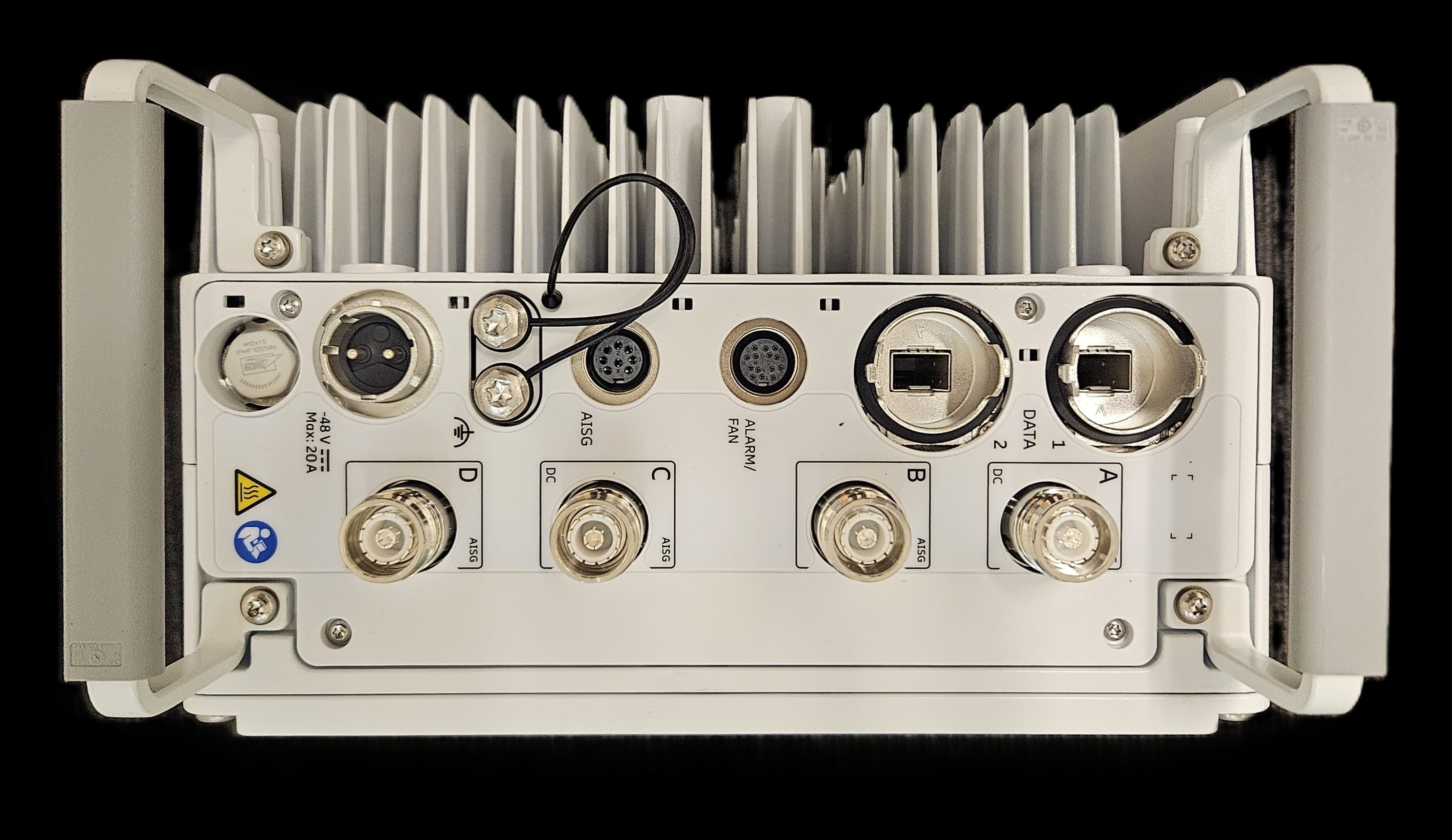
TA8AKRC163007
Jun 19, 2026Radio Unit
Equipment Class
PCB - PCS Licensed Transmitter