TC2-R1009Media Player Device
Roku, Inc.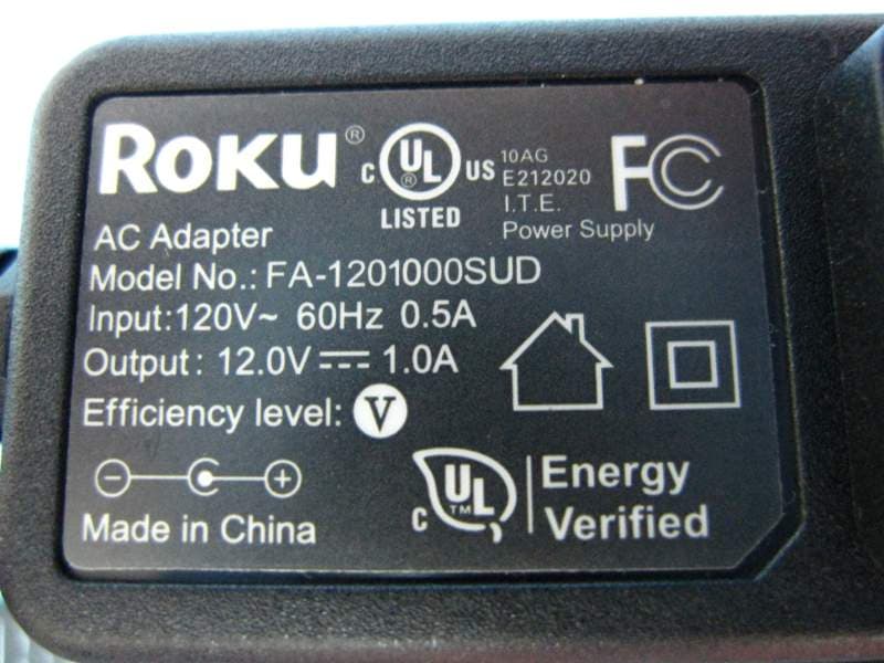
Click to zoom
Application Details
- Equipment Class
- DTS - Digital Transmission System
- Date of Grant
- Nov 16, 2015
- Application Purpose
- Original Equipment
- Date of Application
- Nov 15, 2015
- Equipment Note
- Media Player Device
- Frequency Range
- 2412.00000000 - 2462.00000000
- Company
- Roku, Inc.
- Country
- United States
Documents & Files
Document Text
Text extracted from the exhibit documents filed with the FCC. Open a document above to read the original.
Users Manual
Hi!Let’s get you started. 2 1 5 26 37 4 Status light – Flashes slowly when the Roku player starts up. Glows when it’s on. Flashes once with each press of the remote control. USB port – Connect a compatible USB device for browsing photos, music and movies. Power port – Connect your player to the power source with the included power cable. Reset Button - Reset your Roku player (you probably won’t ever have to use this) Ethernet port – Connect your Roku player to a wired network with an Ethernet cable (not included). HDMI port – Connect your player to an HDTV with an HDMI cable (not included). Storage expansion slot – Connect a microSD card (not included) to expand internal storage for channels and games. Front view Back view Get to know your Roku 2 1 2 3 4 5 6 7 [BACK] Return to previous screen [HOME] Return to Roku home screen [UP] or [DOWN] Move up or down; [LEFT] or [RIGHT] Move left or right [OK] Select an option from a menu [INSTANT REPLAY] Replay last 7 seconds of video [OPTIONS] View more options [REV SCAN] Rewind, scroll left one page at a time [FWD SCAN] Fast forward, scroll right one page at a time [PLAY/PAUSE] Start or pause playback [CHANNEL SHORTCUT] Instant access to favorite channels B H J A E I G A D G E I C B D F H J C F Get to know your Remote What to do Step 1 Connect your player Connect your Roku player to your HDTV with the HDMI cable. ™ What to do Step 2 Next, connect your included power adapter to your Roku player, and then plug the adapter into an outlet. Finally, power on your TV and look for a Roku message to fill the screen. What to do Step 3 Power up your remote •Power your Roku remote by inserting the included batteries. •Insert each battery, negative (-) side first, pushing it into the coil and then into the compartment. DO NOT insert batteries positive (+) side first. Place the battery door back over the compartment and press it gently down until the latch snaps securely into place. Never use damaged batteries. If your remote gets warm/hot during use, discontinue use and contact Roku Customer Support immediately at http://support.roku.com. What to do Step 4 Connect to your network Step 4 establishes your network connection. You can do it! Just choose either wireless or wired and read on for instructions: Wireless: If you use a wireless network, grab that Roku remote and jump right into Guided Setup. When prompted, select “Wireless” as your network connection and have your network name and password ready. Then: •Select your network from the list of available networks. •Enter your network password, if you use one. Remember that network passwords are case sensitive. Wired: If you use a wired network, this step is a snap. Simply connect the Ethernet port on the back of your Roku player to the back of your router with an Ethernet cable (not included), and then use your Roku remote to select “Wired” from the on-screen network options. •Connect one end to the Ethernet port on the back of your Roku player. •Connect the other end to an open Ethernet port on your router. What to do Step 5 Complete guided setup It’s the final stretch. Continue following the on-screen instructions and you’ll: •Get the latest software. •Link the Roku player to your Roku account on your computer. •During Guided Setup, you’ll be prompted to create your Roku account online at http://roku.com/link •Your Roku player will generate a unique code that links your player to your new account. Setup is done. Congratulations! Continue using your Roku remote to personalize your channel line-up, stream movies or play games. The fun has just begun, we promise. Your Roku account: Roku accounts are free. And while a valid credit card number is required to create your account, rest assured you will only be charged if you authorize purchases of channels and games from the Roku Channel Store. Choose & Personalize Your homescreen is yours to personalize. Select your favorite channels from over 2000 choices* in the Roku Channel store. Then, arrange the channels in the order that’s best for you. Control with Ease Both our simple remote and our mobile app let you navigate with ease. Here’s a hint: Try the star button on any screen or channel to access an options menu. Search Find what you want to watch by searching across top streaming channels. Then, choose the best option or value. Follow movies, actors, TV shows & episodes, to get updates when your favorites are ready to watch. Cast Media Cast and mirror videos, music, photos, and more from your mobile devices** to your TV. Use the Roku app, Netflix and YouTube apps, or built in screen mirroring capabilities. Get the most out of your Roku player *Subscription or other payment may be required to access certain content. Channel availability subject to change. **Applies to select iOS®, Android™ and Windows® devices only. For more information, please visit http://support.roku.com. Having trouble completing Guided Setup? Don’t worry. It’s usually an easy fix. For detailed trouble-shooting, visit http://support.roku.com. If you cannot see a picture on your TV: •If you are using HDMI with a home theater receiver, make sure the HDMI cable from your Roku player is connected to an HDMI-in port on your receiver and your receiver is connected to your TV via an HDMI input. •Make sure the video input on your TV or home theater receiver is set to match the output used with the Roku player. Most TVs have an Input button on the remote control to change video inputs. If you cannot connect to your wireless home network during guided setup: •If you are not getting 3 or more signal-strength bars above your wireless network, adjust the location of your Roku player and/or wireless router. •Try to avoid obstructions, like cement walls, between your Roku player and your wireless router. •If you have turned off SSID broadcasting on your wireless router, you can add your network by selecting “My network is not shown” from the “Select wireless network” screen. Troubleshooting Dos and don…
Text truncated - open the document above for the full version.
External Photos
Report No.: 561812 SPORTON International Inc. PAGE NUMBER : 1 of 10 TEL : 886-3-327-3456 ISSUED DATE : Sep. 16, 2015 FAX : 886-3-327-0973 Photographs of EUT Report No.: 561812 SPORTON International Inc. PAGE NUMBER : 2 of 10 TEL : 886-3-327-3456 ISSUED DATE : Sep. 16, 2015 FAX : 886-3-327-0973 Report No.: 561812 SPORTON International Inc. PAGE NUMBER : 3 of 10 TEL : 886-3-327-3456 ISSUED DATE : Sep. 16, 2015 FAX : 886-3-327-0973 Report No.: 561812 SPORTON International Inc. PAGE NUMBER : 4 of 10 TEL : 886-3-327-3456 ISSUED DATE : Sep. 16, 2015 FAX : 886-3-327-0973 Remote controller 1 Model No.: RXT9000-5502EC Report No.: 561812 SPORTON International Inc. PAGE NUMBER : 5 of 10 TEL : 886-3-327-3456 ISSUED DATE : Sep. 16, 2015 FAX : 886-3-327-0973 Report No.: 561812 SPORTON International Inc. PAGE NUMBER : 6 of 10 TEL : 886-3-327-3456 ISSUED DATE : Sep. 16, 2015 FAX : 886-3-327-0973 Remote controller 2 Model No.: RC16D-1, RC16D-2, RC16D-RC52 Report No.: 561812 SPORTON International Inc. PAGE NUMBER : 7 of 10 TEL : 886-3-327-3456 ISSUED DATE : Sep. 16, 2015 FAX : 886-3-327-0973 Adapter 1 Model No.: FA-1201000SUD Report No.: 561812 SPORTON International Inc. PAGE NUMBER : 8 of 10 TEL : 886-3-327-3456 ISSUED DATE : Sep. 16, 2015 FAX : 886-3-327-0973 Report No.: 561812 SPORTON International Inc. PAGE NUMBER : 9 of 10 TEL : 886-3-327-3456 ISSUED DATE : Sep. 16, 2015 FAX : 886-3-327-0973 Adapter 2 Model No.: MU12AH120100-A1 Report No.: 561812 SPORTON International Inc. PAGE NUMBER : 10 of 10 TEL : 886-3-327-3456 ISSUED DATE : Sep. 16, 2015 FAX : 886-3-327-0973
ID Label/Location Info
OVERALL FEATURE TOLERANCE FROM NOMINAL IGES GEOMETRY TO BE ± 0.15MM UNLESS 1. CRITICAL TOLERANCE INDICATED. ALL GATES AND EJECTION PINS TO BE PLACED ON INTERNAL SURFACES.2. ALL EXTERNAL SURFACES TO BE FREE OF ALL FOREIGN PARTICLES, FLOW LINES, WELD LINES, 3. GATE BLUSH, FLASH, SINK OR ANY OTHER TOOLING/MOLDING DEFECTS. MATERIALS: 4. FOOT: RUBBER COLOR, FINISH, SEE CMF DOCUMENTS5. DRAFT ANGLES TO BE 1 FOR UNTEXTURED SURFACES AND 2.5 FOR TEXTURED SURFACES6. SCULPTED SURFACES REFER TO 3D FILE PROVIDED BY ROKU7. ONE HALF OF A FEATURE DIMENSIONED ACROSS A CENTER LINE AND/OR A SYMETRICAL CALL-OUT 8. IS EQUAL TO THE DIMENSION SHOWN DIVIDED BY 2 AND ITS TOLERANCE DIVIDED BY 2 GATE TRIM TO BE 0.5 MAXIMUM, IF NO FUNCTIONAL IMPACT IN ASSEMBLY9. NO SINK OR DEPRESSIONS TO BE VISIBLE ON APPEARANCE SURFACES. 10. APPEARANCE SURFACES TO BE FREE OF COSMETIC DEFECTS, INCLUDING, BUT NOT LIMITED TO 11. SPLAY, PARTICLES, BURNED PLASTIC/MARKS, AND SIMILAR IMPERFECTIONS. PART TO BE FREE OF MOLD RELEASE12. MOLD DESIGN TO MINIMIZE EJECTION MARKS, GATE BLUSH, FLOW LINES AND WELD MARKS. MOLD 13. CONSTRUCTION TO CONFORM TO GOOD MOLDING INDUSTRY STANDARDS PRACTICE AS STATED IN THE CURRENT EDITION OF STANDARDS AND PRACTICES OF PLASTIC CUSTOM MOLDERS BY THE SOCIETY OF THE PLASTICS INDUSTRY, INC. PARTING LINE MISMATCH AND FLASH NOT TO EXCEED 0.15 TOTAL. 14. MOLD TO BE PROPERTY OF ROKU AND SHALL BE PERMANENTLY MARKED WITH "ROKU" AND ITS 15. TOOL #. EJECTOR PIN, PARTING LINE, AND GATE LOCATIONS MUST BE APPROVED BY ROKU DESIGN 16. ENGINEERING PRIOR TO MOLD FABRICATION. EJECTOR PIN MARKS TO BE FLUSH TO 0.1 DEPRESSED, AND 0.10 FLASH IS ALLOWED. BURR AND FLASH: ALL INTERNAL BURRS AND FLUSHES ARE ALLOWED UP TO 0.5MM HIGH MAX. AS 17. LONG AS THE BURRS OR FLASHES DO NOT TOUCH WITH ANY OTHER STEADY OR MOVING COMPONENTS AND CAUSE RELIABILITY OR FUNCTIONAL IMPACT, AND AS LONG AS THEY CANNOT BE SEEN ANYWHERE OUTSIDE OF THE PRODUCT ASSEMBLY. DIMENSIONS MARKED WITH " " ARE FOR INCOMING AND FIRST ARTICLE INSPECTION. 18. -DIMENSIONS MARKED TO ARE FOR FIRST ARTICLE INSPECTION. -DIMENSIONS MARKED TO ARE FOR TOOLING MEASUREMENT 19. INSPECTION DIMENSIONS SHOULD BE MEASURED WITH FOLLOWING EQUIPMENT: ---PROJECTOR: ---CALIPER: 1.50 76.91 A A REGULATORY INFO. AND ICONS TO HAVE GLOSS FINISH 35.00 6.00 80.16 0.50 SECTION A-A NOTES UNLESS OTHERWISE SPECIFIED: REVISIONS REV.DESCRIPTIONDRAWN BYAPPROVEDDATE 001INITIAL RELEASETANNER9/9/15 D C B A B C D 123 45 6 7 8 8 7 6 5 4 3 2 1 E F E F A 001 MUSTANG FOOT 4230X2 LITEON CLIENT:ROKU THIRD ANGLE PROJECTION THE INFORMATION CONTAINED IN THIS DRAWING IS THE SOLE PROPERTY OF . ANY REPRODUCTION IN PART OR AS A WHOLEWITHOUT THE WRITTEN PERMISSION OF IS PROHIBITED. PROPRIETARY AND CONFIDENTIAL DRAWN CHECKED ENG APPR. MFG APPR. Q.A. DATE NAME mustang_foot_4230x2_001 SIZE C PART NO.: REV WEIGHT: SCALE: 1:1 SHEET 1 OF 1 DESCRIPTION UNITS: DO NOT SCALE mm^3 VOLUME FINISH MATERIAL °0.5± ANGLES: 0.05mm±.XXX 0.1mm±.XXDECIMALS: 0.2mm±.X GENERAL TOLERANCE (UNLESS OTHERWISE SPECIFIED) TANNER 09/09/15 OVERALL FEATURE TOLERANCE FROM NOMINAL IGES GEOMETRY TO BE ± 0.15MM UNLESS 1. CRITICAL TOLERANCE INDICATED. ALL GATES AND EJECTION PINS TO BE PLACED ON INTERNAL SURFACES.2. ALL EXTERNAL SURFACES TO BE FREE OF ALL FOREIGN PARTICLES, FLOW LINES, WELD LINES, 3. GATE BLUSH, FLASH, SINK OR ANY OTHER TOOLING/MOLDING DEFECTS. MATERIALS: 4. FOOT: RUBBER COLOR, FINISH, SEE CMF DOCUMENTS5. DRAFT ANGLES TO BE 1 FOR UNTEXTURED SURFACES AND 2.5 FOR TEXTURED SURFACES6. SCULPTED SURFACES REFER TO 3D FILE PROVIDED BY ROKU7. ONE HALF OF A FEATURE DIMENSIONED ACROSS A CENTER LINE AND/OR A SYMETRICAL CALL-OUT 8. IS EQUAL TO THE DIMENSION SHOWN DIVIDED BY 2 AND ITS TOLERANCE DIVIDED BY 2 GATE TRIM TO BE 0.5 MAXIMUM, IF NO FUNCTIONAL IMPACT IN ASSEMBLY9. NO SINK OR DEPRESSIONS TO BE VISIBLE ON APPEARANCE SURFACES. 10. APPEARANCE SURFACES TO BE FREE OF COSMETIC DEFECTS, INCLUDING, BUT NOT LIMITED TO 11. SPLAY, PARTICLES, BURNED PLASTIC/MARKS, AND SIMILAR IMPERFECTIONS. PART TO BE FREE OF MOLD RELEASE12. MOLD DESIGN TO MINIMIZE EJECTION MARKS, GATE BLUSH, FLOW LINES AND WELD MARKS. MOLD 13. CONSTRUCTION TO CONFORM TO GOOD MOLDING INDUSTRY STANDARDS PRACTICE AS STATED IN THE CURRENT EDITION OF STANDARDS AND PRACTICES OF PLASTIC CUSTOM MOLDERS BY THE SOCIETY OF THE PLASTICS INDUSTRY, INC. PARTING LINE MISMATCH AND FLASH NOT TO EXCEED 0.15 TOTAL. 14. MOLD TO BE PROPERTY OF ROKU AND SHALL BE PERMANENTLY MARKED WITH "ROKU" AND ITS 15. TOOL #. EJECTOR PIN, PARTING LINE, AND GATE LOCATIONS MUST BE APPROVED BY ROKU DESIGN 16. ENGINEERING PRIOR TO MOLD FABRICATION. EJECTOR PIN MARKS TO BE FLUSH TO 0.1 DEPRESSED, AND 0.10 FLASH IS ALLOWED. BURR AND FLASH: ALL INTERNAL BURRS AND FLUSHES ARE ALLOWED UP TO 0.5MM HIGH MAX. AS 17. LONG AS THE BURRS OR FLASHES DO NOT TOUCH WITH ANY OTHER STEADY OR MOVING COMPONENTS AND CAUSE RELIABILITY OR FUNCTIONAL IMPACT, AND AS LONG AS THEY CANNOT BE SEEN ANYWHERE OUTSIDE OF THE PRODUCT ASSEMBLY. DIMENSIONS MARKED WITH " " ARE FOR INCOMING AND FIRST ARTICLE INSPECTION. 18. -DIMENSIONS MARKED TO ARE FOR FIRST ARTICLE INSPECTION. -DIMENSIONS MARKED TO ARE FOR TOOLING MEASUREMENT 19. INSPECTION DIMENSIONS SHOULD BE MEASURED WITH FOLLOWING EQUIPMENT: ---PROJECTOR: ---CALIPER: 1.50 76.91 A A REGULATORY INFO. AND ICONS TO HAVE GLOSS FINISH 35.00 6.00 80.16 0.50 SECTION A-A NOTES UNLESS OTHERWISE SPECIFIED: REVISIONS REV.DESCRIPTIONDRAWN BYAPPROVEDDATE 001INITIAL RELEASETANNER9/9/15 D C B A B C D 123 45 6 7 8 8 7 6 5 4 3 2 1 E F E F A 001 MUSTANG FOOT 4210X2 LITEON CLIENT:ROKU THIRD ANGLE PROJECTION THE INFORMATION CONTAINED IN THIS DRAWING IS THE SOLE PROPERTY OF . ANY REPRODUCTION IN PART OR AS A WHOLEWITHOUT THE WRITTEN PERMISSION OF IS PROHIBITED. PROPRIETARY AND CONFIDENTIAL DRAWN CHECKED ENG APPR. MFG APPR. Q.A. DATE NAME mustang_foot_4210x2_001 SIZE C PART NO.: REV WEIGHT: SCALE: 1:1 SHEET 1 OF 1 DESCRIPTION UNITS: DO NOT SCALE mm^3 VOLUME FINISH MATERIAL °0.5± ANGLES: 0.05mm±.XXX 0.1mm±.XXDECIMALS: 0.2mm±.X GENERAL TOLERAN…
Text truncated - open the document above for the full version.
Internal Photos
Report No.: 561812 SPORTON International Inc. PAGE NUMBER : 1 of 16 TEL : 886-3-327-3456 ISSUED DATE : Sep. 16, 2015 FAX : 886-3-327-0973 Photographs of EUT Report No.: 561812 SPORTON International Inc. PAGE NUMBER : 2 of 16 TEL : 886-3-327-3456 ISSUED DATE : Sep. 16, 2015 FAX : 886-3-327-0973 Report No.: 561812 SPORTON International Inc. PAGE NUMBER : 3 of 16 TEL : 886-3-327-3456 ISSUED DATE : Sep. 16, 2015 FAX : 886-3-327-0973 Report No.: 561812 SPORTON International Inc. PAGE NUMBER : 4 of 16 TEL : 886-3-327-3456 ISSUED DATE : Sep. 16, 2015 FAX : 886-3-327-0973 Report No.: 561812 SPORTON International Inc. PAGE NUMBER : 5 of 16 TEL : 886-3-327-3456 ISSUED DATE : Sep. 16, 2015 FAX : 886-3-327-0973 Report No.: 561812 SPORTON International Inc. PAGE NUMBER : 6 of 16 TEL : 886-3-327-3456 ISSUED DATE : Sep. 16, 2015 FAX : 886-3-327-0973 Report No.: 561812 SPORTON International Inc. PAGE NUMBER : 7 of 16 TEL : 886-3-327-3456 ISSUED DATE : Sep. 16, 2015 FAX : 886-3-327-0973 Report No.: 561812 SPORTON International Inc. PAGE NUMBER : 8 of 16 TEL : 886-3-327-3456 ISSUED DATE : Sep. 16, 2015 FAX : 886-3-327-0973 Remote controller 1 Model No.: RXT9000-5502EC Report No.: 561812 SPORTON International Inc. PAGE NUMBER : 9 of 16 TEL : 886-3-327-3456 ISSUED DATE : Sep. 16, 2015 FAX : 886-3-327-0973 Report No.: 561812 SPORTON International Inc. PAGE NUMBER : 10 of 16 TEL : 886-3-327-3456 ISSUED DATE : Sep. 16, 2015 FAX : 886-3-327-0973 Report No.: 561812 SPORTON International Inc. PAGE NUMBER : 11 of 16 TEL : 886-3-327-3456 ISSUED DATE : Sep. 16, 2015 FAX : 886-3-327-0973 Report No.: 561812 SPORTON International Inc. PAGE NUMBER : 12 of 16 TEL : 886-3-327-3456 ISSUED DATE : Sep. 16, 2015 FAX : 886-3-327-0973 Report No.: 561812 SPORTON International Inc. PAGE NUMBER : 13 of 16 TEL : 886-3-327-3456 ISSUED DATE : Sep. 16, 2015 FAX : 886-3-327-0973 Remote controller 2 Model No.: RC16D-1, RC16D-2, RC16D-RC52 Report No.: 561812 SPORTON International Inc. PAGE NUMBER : 14 of 16 TEL : 886-3-327-3456 ISSUED DATE : Sep. 16, 2015 FAX : 886-3-327-0973 Report No.: 561812 SPORTON International Inc. PAGE NUMBER : 15 of 16 TEL : 886-3-327-3456 ISSUED DATE : Sep. 16, 2015 FAX : 886-3-327-0973 Report No.: 561812 SPORTON International Inc. PAGE NUMBER : 16 of 16 TEL : 886-3-327-3456 ISSUED DATE : Sep. 16, 2015 FAX : 886-3-327-0973
RF Exposure Info
Report No.: FA561812 Report Format Version: 01 Page No. : i of ii FCC ID : TC2-R1009 Issued Date : Nov. 16, 2015 Table of Contents 1. GENERAL DESCRIPTION.................................................................................................................................... 1 1.1. EUT General Information .....................................................................................................................................................................1 1.2. Table for Multiple Listing......................................................................................................................................................................1 1.3. Testing Location..................................................................................................................................................................................1 2. MAXIMUM PERMISSIBLE EXPOSURE.................................................................................................................... 2 2.1. Limit of Maximum Permissible Exposure ..............................................................................................................................................2 2.2. MPE Calculation Method ....................................................................................................................................................................2 2.3. Calculated Result and Limit................................................................................................................................................................3 Report No.: FA561812 Report Format Version: 01 Page No. : ii of ii FCC ID : TC2-R1009 Issued Date : Nov. 16, 2015 History of This Test Report REPORT NO. VERSION DESCRIPTION ISSUED DATE FA561812 Rev. 01 Initial issue of report Nov. 16, 2015 Report No.: FA561812 Report Format Version: 01 Page No. : 1 of 3 FCC ID : TC2-R1009 Issued Date : Nov. 16, 2015 1. GENERAL DESCRIPTION 1.1. EUT General Information RF General Information Evaluation Mode Frequency Range (MHz) Operating Frequency (MHz) Modulation Type 2.4GHz WLAN 2400-2483.5 2412-2462 802.11b: DSSS (DBPSK, DQPSK, CCK) 802.11g/n: OFDM (BPSK, QPSK, 16QAM, 64QAM) 5GHz WLAN 5150-5250 5725-5850 5180-5240 5745-5825 802.11a/n: OFDM (BPSK, QPSK, 16QAM, 64QAM) 1.2. Table for Multiple Listing The EUT has two model names which are identical to each other in all aspects except for the following table: Model Name Remote controller 1 Remote controller 2 Description 4210X2 X V 4230X2 V X These two models are identical except for the different remote controllers. From the above models, model: 4210X2 was selected as representative model for the test and its data was recorded in this report. 1.3. Testing Location Testing Location HWA YA ADD : No. 52, Hwa Ya 1st Rd., Kwei-Shan Hsiang, Tao Yuan Hsien, Taiwan, R.O.C. TEL : 886-3-327-3456 FAX : 886-3-327-0973 JHUBEI ADD : No.8, Lane 724, Bo-ai St., Jhubei City, HsinChu County 302, Taiwan, R.O.C. TEL : 886-3-656-9065 FAX : 886-3-656-9085 Report No.: FA561812 Report Format Version: 01 Page No. : 2 of 3 FCC ID : TC2-R1009 Issued Date : Nov. 16, 2015 2. MAXIMUM PERMISSIBLE EXPOSURE 2.1. Limit of Maximum Permissible Exposure (A) Limits for Occupational / Controlled Exposure Frequency Range (MHz) Electric Field Strength (E) (V/m) Magnetic Field Strength (H) (A/m) Power Density (S) (mW/ cm²) Averaging Time |E|²,|H|² or S (minutes) 0.3-3.0 614 1.63 (100)* 6 3.0-30 1842 / f 4.89 / f (900 / f)* 6 30-300 61.4 0.163 1.0 6 300-1500 F/300 6 1500-100,000 5 6 (B) Limits for General Population / Uncontrolled Exposure Frequency Range (MHz) Electric Field Strength (E) (V/m) Magnetic Field Strength (H) (A/m) Power Density (S) (mW/ cm²) Averaging Time |E|²,|H|² or S (minutes) 0.3-1.34 614 1.63 (100)* 30 1.34-30 824/f 2.19/f (180/f)* 30 30-300 27.5 0.073 0.2 30 300-1500 F/1500 30 1500-100,000 1.0 30 Note: f = frequency in MHz ; *Plane-wave equivalent power density 2.2. MPE Calculation Method The MPE was calculated at 20 cm to show compliance with the power density limit. The following formula was used to calculate the Power Density: E (V/m) = d GP30 Power Density: Pd (W/m²) = 377 2 E E = Electric field (V/m) P = Peak RF output power (W) G = EUT Antenna numeric gain (numeric) d = Separation distance between radiator and human body (m) The formula can be changed to Pd = 2 377 30 d GP Report No.: FA561812 Report Format Version: 01 Page No. : 3 of 3 FCC ID : TC2-R1009 Issued Date : Nov. 16, 2015 2.3. Calculated Result and Limit Exposure Environment: General Population / Uncontrolled Exposure For 5GHz Band : Antenna Type : Printed Antenna Conducted Power for IEEE 802.11n MCS0 HT20: 20.21 dBm The maximum combined Average Output Power Distance (cm) Test Freq. (MHz) Antenna Gain (dBi) Antenna Gain (numeric) (dBm) (mW) Power Density (S) (mW/cm²) Limit of Power Density (S) (mW/cm²) Test Result 20 5200 3.60 2.2909 20.2053 104.8413 0.047806 1 Complies For 2.4GHz Band: Antenna Type : Printed Antenna Conducted Power for IEEE 802.11n MCS0 HT20: 20.30 dBm The maximum combined Average Output Power Distance (cm) Test Freq. (MHz) Antenna Gain (dBi) Antenna Gain (numeric) (dBm) (mW) Power Density (S) (mW/cm²) Limit of Power Density (S) (mW/cm²) Test Result 20 2437 2.10 1.6218 20.3029 107.2233 0.034613 1 Complies
Test Report
SPORTON International Inc. No. 52, Hwa Ya 1st Rd., Hwa Ya Technology Park, Kwei-Shan Hsiang, Tao Yuan Hsien, Taiwan, R.O.C. Ph: 886-3-327-3456 / FAX: 886-3-327-0973 / www.sporton.com.tw Report Format Version: Rev. 01 FCC RADIO TEST REPORT Applicant’s company Roku, Inc. Applicant Address 12980 Saratoga Avenue Suite #D Saratoga California United States 95070 FCC ID TC2-R1009 Manufacturer’s company Lite-On Network Communication (Dongguan) Limited Manufacturer Address 30#Keji Rd., Yin Hu Industrial Area, Qingxi Town, DongGuan City, Guangdong, China Product Name Media Player Device Brand Name Roku Model No. 4210X2, 4230X2 Test Rule 47 CFR FCC Part 15 Subpart C § 15.247 Test Freq. Range 2400 ~ 2483.5MHz Received Date Apr. 30, 2015 Final Test Date Nov. 09, 2015 Submission Type Original Equipment Statement Test result included in this report is for the IEEE 802.11n and IEEE 802.11b/g of the product. The test result in this report refers exclusively to the presented test model / sample. Without written approval of SPORTON International Inc., the test report shall not be reproduced except in full. The measurements and test results shown in this test report were made in accordance with the procedures and found in compliance with the limit given in ANSI C63.10-2013, 47 CFR FCC Part 15 Subpart C, KDB558074 D01 v03r03 and KDB 662911 D01 v02r01. The test equipment used to perform the test is calibrated and traceable to NML/ROC. Report No.: FR561812AA Report Format Version: Rev. 01 Page No. : i of ii FCC ID: TC2-R1009 Issued Date : Nov. 16, 2015 Table of Contents 1. VERIFICATION OF COMPLIANCE ....................................................................................................................... 1 2. SUMMARY OF THE TEST RESULT .......................................................................................................................... 2 3. GENERAL INFORMATION .................................................................................................................................. 3 3.1. Product Details....................................................................................................................................................................................3 3.2. Accessories .........................................................................................................................................................................................4 3.3. Table for Filed Antenna.......................................................................................................................................................................5 3.4. Table for Carrier Frequencies .............................................................................................................................................................6 3.5. Table for Test Modes ...........................................................................................................................................................................7 3.6. Table for Testing Locations..................................................................................................................................................................8 3.7. Table for Multiple Listing......................................................................................................................................................................8 3.8. Table for Supporting Units ...................................................................................................................................................................9 3.9. Table for Parameters of Test Software Setting ...................................................................................................................................10 3.10. EUT Operation during Test .................................................................................................................................................................10 3.11. Duty Cycle ........................................................................................................................................................................................10 3.12. Test Configurations ...........................................................................................................................................................................11 4. TEST RESULT ................................................................................................................................................... 14 4.1. AC Power Line Conducted Emissions Measurement.........................................................................................................................14 4.2. Maximum Conducted Output Power Measurement .........................................................................................................................18 4.3. Power Spectral Density Measurement ..............................................................................................................................................20 4.4. 6dB Spectrum Bandwidth Measurement ..........................................................................................................................................25 4.5. Radiated Emissions Measurement ....................................................................................................................................................31 4.6. Emissions Measurement ....................................................................................................................................................................46 4.7. Antenna Requirements .....................................................................................................................................................................60 5. LIST OF MEASURING EQUIPMENTS .........................................................................................................…
Text truncated - open the document above for the full version.
Test Setup Photos
Report No.: FR561812 FCC ID: TC2-R1009 Page No. : A1 of A5 Appendix A. Test Photos Report No.: FR561812 FCC ID: TC2-R1009 Page No. : A2 of A5 1. Photographs of Conducted Emissions Test Configuration Test Mode: Mode 5 FRONT VIEW REAR VIEW Report No.: FR561812 FCC ID: TC2-R1009 Page No. : A3 of A5 2. Photographs of Radiated Emissions Test Configuration Test Configuration: 9kHz ~30MHz / Test Mode: Mode 9 FRONT VIEW REAR VIEW Report No.: FR561812 FCC ID: TC2-R1009 Page No. : A4 of A5 Test Configuration: 30MHz~1GHz / Test Mode: Mode 9 FRONT VIEW REAR VIEW Report No.: FR561812 FCC ID: TC2-R1009 Page No. : A5 of A5 Test Configuration: Above 1GHz FRONT VIEW REAR VIEW
Contact Information
Applicant
Robert Curtis(VP Engineering)
Test Firm
Sporton International Inc.Alex Chen
Technical Specifications
| # | Rule Parts | Frequency Range | Power Output |
|---|---|---|---|
| 1 | 15C | 2.41 GHz - 2.46 GHz | 107.00 mW |
Other Applications from Roku, Inc.
TC2-R1053
Aug 03, 2026Enhanced Voice Remote
Equipment Class
DTS - Digital Transmission SystemTC2-R1050
Sep 23, 2024Streaming Player
Equipment Class
DSS - Part 15 Spread Spectrum Transmitter
TC2-R1043
Nov 19, 2023Streaming Player with Built-in Speaker
Equipment Class
DTS - Digital Transmission System
TC2-R1040
Apr 12, 2021Set-top-box
Equipment Class
NII - Unlicensed National Information Infrastructure TX
TC2-R1039
Nov 22, 2020Remote Control
Equipment Class
NII - Unlicensed National Information Infrastructure TX