TC2-R1037Remote Control
Roku, Inc.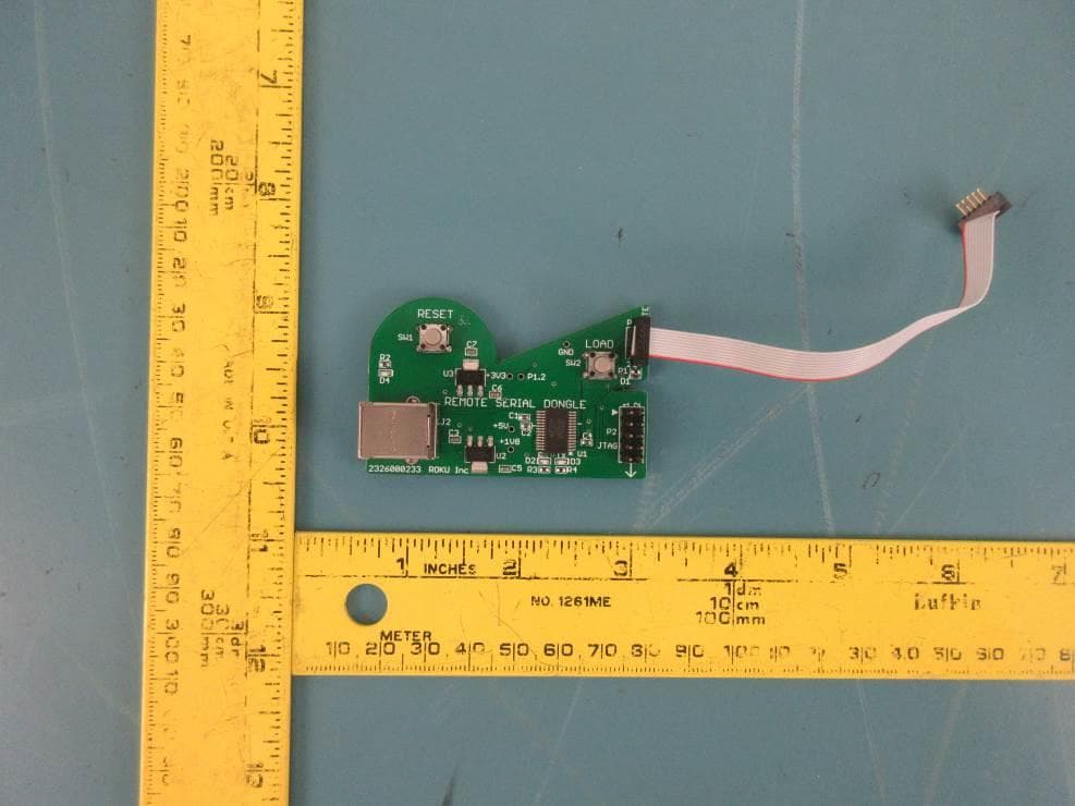
Click to zoom
Application Details
- Equipment Class
- NII - Unlicensed National Information Infrastructure TX
- Date of Grant
- Jun 25, 2020
- Application Purpose
- Original Equipment
- Date of Application
- Jun 25, 2020
- Equipment Note
- Remote Control
- Frequency Range
- 5745.00000000 - 5825.00000000
- Company
- Roku, Inc.
- Country
- United States
Documents & Files
Document Text
Text extracted from the exhibit documents filed with the FCC. Open a document above to read the original.
Users Manual
5 © 2019 Roku, Inc. All rights reserved. ROKU, ROKU logo and STREAMING STICK are the registered trademarks of Roku, Inc. All other logos and trademarks herein not owned by Roku, Inc. are the property of their respective owners. Video tutorials Add channels Wireless help Mobile app Need more help getting started? go.roku.com/rssplus Getting the most out of your Roku streaming player. go.roku.com/usingroku Tips, what’s streaming for free, and more... blog.roku.com STEP 5: On-screen setup and activation Follow the instructions on your TV screen. Activate your streaming player by using your computer or smartphone to link to a Roku account. Roku Blog Let’s get started English Deutsch Español Français 12:40 pm | Options Quick Start Guide + Common questions Why do I need to create a Roku account? Before you can start streaming, channels must be downloaded and installed on your streaming player. You’ll need a Roku account to access the Roku Channel Store, manage your subscriptions, view your purchase history, and add a payment method. For more info, visit go.roku.com/whyaccount Why do I need to enter a credit card? Saving a payment method makes it easy to rent or buy movies on demand, subscribe to popular services, and enroll in free trials. Charges will not be made without your authorization. For more information, visit go.roku.com/paymenthelp What should I do if my streaming player is not connecting to my wireless network? Your streaming player connects to your wireless network the same as your laptop or smartphone. If these other devices can access the internet, then your streaming player should be able to do the same. Make sure to select the same network name, and enter the same password you use with the other devices. Remember that passwords are case- sensitive and easy to enter incorrectly. For more help, visit go.roku.com/wireless Can I take my Roku streaming player with me when I travel? Yes. You can bring your streaming player and watch your favorite entertainment when you travel. Remember to also bring a USB power adaptor (like your phone charger), remote, and any cables you use to connect your streaming player at home. Make sure your destination has a good internet connection. You may need a computer or smartphone to help connect your streaming player to a new wireless network. For more details, visit go.roku.com/travelwithroku HEADPHONE EDITION NOTE: Roku does not charge for activation support – beware of scams. 4100000555_1 1 OR 3 4 2 OR What’s includedSetup STEP 1: Connect to TV HDTVs: Plug your streaming player into an HDMI® port on your TV. 4K and HDR TVs: To stream 4K or HDR, choose an HDMI port that supports HDCP 2.2. For help determining which port supports HDCP 2.2, visit go.roku.com/hdcp STEP 2: Connect to power For the best streaming experience, use the included USB power cable, power extender cable and power adaptor to connect your streaming player to a wall outlet. STEP 3: Power on TV and select input Use your TV remote to power on your TV and select the input you used to connect your streaming player. For help on how to select the correct input, visit go.roku.com/selectinput STEP 4: Insert batteries On the back side of the remote, slide open the battery cover. Insert included Duracell® batteries placing the negative (-) ends in fi rst. Your remote should pair with your streaming player automatically. For help pairing your remote, visit go.roku.com/remotehelp Doesn’t fi t? Order a free HDMI extender cable at my.roku.com/HDMI Or use the included USB power cable to connect to the USB port on your TV. NOTE: See a red light on your streaming player? That means the USB port on your TV is not providing enough power. Use the included power adaptor instead. For help, visit go.roku.com/lowpower Roku® Streaming Stick®+ USB power cable with long-range wireless receiver Power adaptor Two AA Duracell® batteries Remote USB power extender cable Power and status light USB power Reset HDMI® connector USB HDMI USB HDMI USB HDMI FREE USB HDMI Antenna A/V 1 HDMI 1 HDMI 2 Input Mute Channel shortcuts Options TV power Instant replay Voice Features Headphone jack for private listening Volume controls Headphones Volume NOTE: To use private listening, simply plug headphones into your Roku remote. Your TV will mute automatically. Headphones for private listening
Cover Letter(s)
QA-FR-172-A FCC Confidential Authorization 2020/06/10 FEDERAL COMMUNICATIONS COMMISSIONS Authorization and Evaluation Division 7435 Oakland Mills Road Columbia, MD 21046 Subject: Confidentiality Request regarding application for certification of FCC ID: TC2-R1037 In accordance with Sections 0.457 and 0.459 of the Commission’s Rules, Roku, Inc. hereby requests long-term confidential treatment of information accompanying this application as outlined below: Block Diagram Schematics Operation Description As well as short-term confidential treatment of information accompanying this application as outlined below: Internal Photos User’s Manual External Photos Test Set-up Photos The above materials contain proprietary and confidential information not customarily released to the public. The public disclosure of these materials provides unjustified benefits to its competitors in the market. Sincerely, Robert Curtis/ Sr. Director SW Eng Roku, Inc. 1155 Coleman Ave San Jose, CA 95110
Cover Letter(s)
DECLARATION OF SIMILARITY June 15, 2020 To: FEDERAL COMMUNICATIONS COMMISSIONS Authorization and Evaluation Division 7435 Oakland Mills Road Columbia, MD 21046 Dear Sir or Madam: We Roku, Inc. hereby declare that product: Remote Control, model: RC-EL2 (FCC ID: TC2- R1037) is electrically identical with the same electromagnetic emissions and electromagnetic compatibility characteristics as model: RC-EL3 tested by BACL, the results of which are featured in BACL project: R2005185. A description of the differences between the tested model and those that are declared similar are as follows: RC-EL3 contains an extra speaker for remote detecting function, and RC-EL2 doesn’t. Also RC- EL3 has extra buttons and RC-EL2 doesn’t Please contact me should there be need for any additional clarification or information. Best Regards, Responsible Party Signature Robert Curtis Director SW Eng 1155 Coleman Ave San Jose, CA 95110
External Photos
Roku Inc. FCC ID: TC2-R1037 EUT External Photographs EUT Top View EUT Bottom View Roku Inc. FCC ID: TC2-R1037 EUT Side View #1 EUT Side View #2 Roku Inc. FCC ID: TC2-R1037 EUT Side View #3 EUT Side View #4 Roku Inc. FCC ID: TC2-R1037 EUT Debug Board with Debug Cable Top View EUT Debug Board with Debug Cable Bottom View Roku Inc. FCC ID: TC2-R1037 USB Cable
ID Label/Location Info
REV.DRAWN BYCHECKED BYDAT EDAT EDESCRIPTION SHEETS REV’D A1 COPE-SUMMERFIELD 122319INITIAL RELEASEALL SHEET 1 OF 1 ROKU PN 7031001474 DESCRIPTION LABEL, BATTERY, RC-EL3, RC506, US ROKU REV. NOTES UNLESS OTHERWISE SPECIFIED 1 2 3 4 5 DO NOT SCALE; ARTWORK PLACEMENT 1:1 LABEL MATERIAL: MYLAR CENTER ARTWORK OVER CENTERLINE COLOR: PMS BLACK C PMS 422 C PRINTING TOLERANCE ± 0.2MM LUONG122319 A2 COPE-SUMMERFIELD 122419UPDATED OUTLINE DIMENSIONS AND ARTWORK POSITION ALLLUONG122419 LUONG010620A3 COPE-SUMMERFIELD 010620UPDATED OUTLINE DIMENSIONS AND ARTWORK POSITION ALL 041420 A4 WOLF041420A4 PERIN 041420UPDATED BATTERY LABEL SIZE ALL Use AA batteriesSKU 3226000852Model: RC-EL3FCC ID: TC2-R1037 Made in China 30.40mm 3.50mm 3.50mm C L 422 CBlack C 52.20mm 3.47mm
Internal Photos
Roku Inc. FCC ID: TC2-R1037 EUT Internal Photographs 1.1 EUT PCB Top View 1.2 EUT PCB Bottom View Roku Inc. FCC ID: TC2-R1037 1.3 EUT PCB Component View Antenna
RF Exposure Info
Roku, Inc. FCC ID: TC2-R1037 Report Number: R2005185-407 Page 13 of 60 FCC Part 15.407 Test Report 4 FCC §2.1093 & §15.407(f) - RF Exposure 4.1 Applicable Standard According to FCC KDB 447498 D01 General RF Exposure Guidance v05r02 Section 4.3.1, Unless specifically required by the published RF exposure KDB procedures, standalone 1-g head or body and 10-g extremity SAR evaluation for general population exposure conditions, by measurement or numerical simulation, is not required when the corresponding SAR Test Exclusion Threshold condition, listed below, is satisfied. These test exclusion conditions are based on source-based time-averaged maximum conducted output power of the RF channel requiring evaluation, adjusted for tune-up tolerance, and the minimum test separation distance required for the exposure conditions. The minimum test separation distance is determined by the smallest distance from the antenna and radiating structures or outer surface of the device, according to the host form factor, exposure conditions and platform requirements, to any part of the body or extremity of a user or bystander (see 5) of section 4.1). To qualify for SAR test exclusion, the test separation distances applied must be fully explained and justified by the operating configurations and exposure conditions of the transmitter and applicable host platform requirements, typically in the SAR measurement or SAR analysis report, according to the required published RF exposure KDB procedures. When no other RF exposure testing or reporting is required, a statement of justification and compliance must be included in the equipment approval, in lieu of the SAR report, to qualify for the SAR test exclusion. When required, the device specific conditions described in the other published RF exposure KDB procedures must be satisfied before applying these SAR test exclusion provisions; for example, handheld PTT two-way radios, handsets, laptops & tablets etc. 1) The 1-g and 10-g SAR test exclusion thresholds for 100 MHz to 6 GHz at test separation distances ≤ 50 mm are determined by: [(max. power of channel, including tune-up tolerance, mW)/(min. test separation distance, mm)] · [√f(GHz)] ≤ 3.0 for 1-g SAR and ≤ 7.5 for 10-g extremity SAR, where • f(GHz) is the RF channel transmit frequency in GHz • Power and distance are rounded to the nearest mW and mm before calculation • The result is rounded to one decimal place for comparison • 3.0 and 7.5 are referred to as the numeric thresholds in the step 2 below The test exclusions are applicable only when the minimum test separation distance is ≤ 50 mm and for transmission frequencies between 100 MHz and 6 GHz. When the minimum test separation distance is < 5 mm, a distance of 5 mm according to 5) in section 4.1 is applied to determine SAR test exclusion. 2) At 100 MHz to 6 GHz and for test separation distances > 50 mm, the SAR test exclusion threshold is determined according to the following, and as illustrated in Appendix B: a) [Power allowed at numeric threshold for 50 mm in step 1) + (test separation distance - 50 mm)·( f(MHz)/150)] mW, at 100 MHz to 1500 MHz b) [Power allowed at numeric threshold for 50 mm in step 1) + (test separation distance - 50 mm)·10] mW at > 1500 MHz and ≤ 6 GHz 3) At frequencies below 100 MHz, the following may be considered for SAR test exclusion, and as illustrated in Appendix C: a) The power threshold at the corresponding test separation distance at 100 MHz in step 2) is multiplied by [1 + log(100/f(MHz))] for test separation distances > 50 mm and < 200 mm b) The power threshold determined by the equation in a) for 50 mm and 100 MHz is multiplied by ½ for test separation distances ≤ 50 mm Roku, Inc. FCC ID: TC2-R1037 Report Number: R2005185-407 Page 14 of 60 FCC Part 15.407 Test Report c) SAR measurement procedures are not established below 100 MHz. When SAR test exclusion cannot be applied, a KDB inquiry is required to determine SAR evaluation requirements for any test results to be acceptable. 4.2 RF Exposure Evaluation Results Customer declares the separation distance between antenna and user’s hand is 10mm. The turn-up conducted power report was 6.01 dBm (3.99 mW). According to KDB 447498D01, [(max. power of channel, including tune-up tolerance, mW)/(min. test separation distance, mm)] · [√f(GHz)] ≤ 3.0 for 1-g SAR and ≤ 7.5 for 10-g extremity SAR. (3.99/10)* √5.24=0.913 which is less than 7.5 SAR testing for this device is excluded.
Test Report
Note: This test report is prepared for the customer shown above and for the device described herein. It may not be duplicated or used in part without prior written consent from Bay Area Compliance Laboratories Corp. This report must not be used by the customer to claim product certification, approval, or endorsement by A2LA*, NIST, or any agency of the Federal Government. * This report may contain data that are not covered by the A2LA accreditation and are marked with an asterisk “*” (Rev.2) FCC PART 15.407 TEST REPORT For Roku, Inc. 1155 Coleman Ave., San Jose, CA 95110, USA FCC ID: TC2-R1037 Report Type: Original Report Model: RC-EL2 & RC-EL3 Prepared By: Zhao Zhao Test Engineer Report Number: R2005185-407 Report Date: 2020-06-22 Reviewed By: Simon Ma RF Supervisor Bay Area Compliance Laboratories Corp. 1274 Anvilwood Avenue, Sunnyvale, CA 94089, USA Tel: +1 (408) 732-9162 Fax: +1 (408) 732-9164 Roku, Inc. FCC ID: TC2-R1037 Report Number: R2005185-407 Page 2 of 60 FCC Part 15.407 Test Report TABLE OF CONTENTS 1 GENERAL DESCRIPTION ......................................................................................................................................... 5 1.1 PRODUCT DESCRIPTION FOR EQUIPMENT UNDER TEST (EUT) ................................................................................. 5 1.2 MECHANICAL DESCRIPTION OF EUT ....................................................................................................................... 5 1.3 OBJECTIVE ............................................................................................................................................................... 5 1.4 RELATED SUBMITTAL(S)/GRANT(S) ........................................................................................................................ 5 1.5 TEST METHODOLOGY .............................................................................................................................................. 5 1.6 MEASUREMENT UNCERTAINTY ............................................................................................................................... 6 1.7 TEST FACILITY REGISTRATIONS .............................................................................................................................. 6 1.8 TEST FACILITY ACCREDITATIONS ............................................................................................................................ 6 2 SYSTEM TEST CONFIGURATION .......................................................................................................................... 9 2.1 JUSTIFICATION ......................................................................................................................................................... 9 2.2 EUT EXERCISE SOFTWARE ...................................................................................................................................... 9 2.3 DUTY CYCLE CORRECTION FACTOR ........................................................................................................................ 9 2.4 EQUIPMENT MODIFICATIONS ................................................................................................................................. 11 2.5 LOCAL SUPPORT EQUIPMENT ................................................................................................................................ 11 2.6 SUPPORT EQUIPMENT ............................................................................................................................................ 11 2.7 INTERFACE PORTS AND CABLING .......................................................................................................................... 11 3 SUMMARY OF TEST RESULTS ............................................................................................................................. 12 4 FCC §2.1093 & §15.407(F) - RF EXPOSURE .......................................................................................................... 13 4.1 APPLICABLE STANDARD ........................................................................................................................................ 13 4.2 RF EXPOSURE EVALUATION RESULTS ................................................................................................................... 14 5 FCC §15.203 - ANTENNA REQUIREMENTS ........................................................................................................ 15 5.1 APPLICABLE STANDARDS ...................................................................................................................................... 15 5.2 ANTENNA LIST ...................................................................................................................................................... 15 6 FCC §15.205, §15.209 & §15.407(B) - SPURIOUS RADIATED EMISSIONS ...................................................... 16 6.1 APPLICABLE STANDARD ........................................................................................................................................ 16 6.2 TEST SETUP ........................................................................................................................................................... 17 6.3 TEST PROCEDURE .................................................................................................................................................. 17 6.4 CORRECTED AMPLITUDE AND MARGIN CALCULATION ......................................................................................... 18 6.5 TEST EQUIPMENT LIST AND DETAILS .................................................................................................................... 18 6.6 TEST ENVIRONMENTAL CONDITIONS ..................................................................................................................... 19 6.7 SUMMARY OF TEST RESULTS ..................................…
Text truncated - open the document above for the full version.
Test Setup Photos
Roku Inc. FCC ID: TC2-R1037 EUT Test Setup Photographs 1.1. EUT Test Setup 30MHz-1GHz Front View (3 meter) 1.2. EUT Test Setup 30MHz-1GHz Rear View (3 meter) Roku Inc. FCC ID: TC2-R1037 1.3. EUT Test Setup 1-18GHz Front View (3 meter) 1.4. EUT Test Setup 1-18GHz Rear View (3 meter) Roku Inc. FCC ID: TC2-R1037 1.5. EUT Test Setup 1-18GHz Front View (1 meter) 1.6. EUT Test Setup 1-18GHz Rear View (1 meter) Roku Inc. FCC ID: TC2-R1037 1.7. EUT Test Setup 18-26.5GHz Front View (1 meter) 1.8. EUT Test Setup 18-26.5GHz Rear View (1 meter) Roku Inc. FCC ID: TC2-R1037 1.9. EUT Test Setup 26.5-40GHz Front View (1 meter) 1.10. EUT Test Setup 26.5-40GHz Rear View (1 meter)
Contact Information
Applicant
Robert Curtis(VP Engineering)
Test Firm
Bay Area Compliance Laboratories Corp.Lisa Tang
Technical Specifications
| # | Rule Parts | Frequency Range | Power Output |
|---|---|---|---|
| 2 | 15E | 5.75 GHz - 5.83 GHz | 3.00 mW |
Other Applications from Roku, Inc.
TC2-R1053
Aug 03, 2026Enhanced Voice Remote
Equipment Class
DTS - Digital Transmission SystemTC2-R1050
Sep 23, 2024Streaming Player
Equipment Class
DSS - Part 15 Spread Spectrum Transmitter
TC2-R1043
Nov 19, 2023Streaming Player with Built-in Speaker
Equipment Class
DTS - Digital Transmission System
TC2-R1040
Apr 12, 2021Set-top-box
Equipment Class
NII - Unlicensed National Information Infrastructure TX
TC2-R1039
Nov 22, 2020Remote Control
Equipment Class
NII - Unlicensed National Information Infrastructure TX