TC22400XIP-STB
Roku, Inc.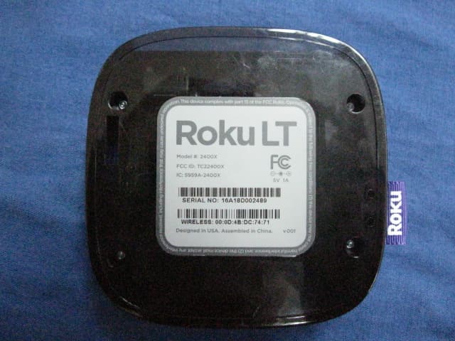
Click to zoom
Application Details
- Equipment Class
- DTS - Digital Transmission System
- Date of Grant
- Sep 26, 2011
- Application Purpose
- Original Equipment
- Date of Application
- Sep 25, 2011
- Equipment Note
- IP-STB
- Frequency Range
- 2412.00000000 - 2462.00000000
- Company
- Roku, Inc.
- Country
- United States
Documents & Files
Document Text
Text extracted from the exhibit documents filed with the FCC. Open a document above to read the original.
Users Manual
Hi! Let’s get started. What’s in the Box Roku playerRemote control 2 x aaa batteries for remote a/V cable RCa to 3.5mm Power adapter C D F e Get to knoW youR roKu B Front view Back view a e F D a status light – Flashes slowly when the Roku player starts up. Glows when it’s on. Flashes once with each press of the remote control. iR receiver – Receives signal from the included Roku remote. hDMi port – Connects your Roku player to an hDtV with an hDMi cable (not included). a/V port – Connects your Roku player to a tV with the included a/V cable (3.5mm to RCa). Provides standard definition quality only. Power port – Connects your Roku player to a 120V aC power source with the included power adapter. Reset button – Resets your Roku player to its original factory settings when pressed and held for 10 seconds (a feature you’ll rarely, if ever, use). C B DiD you notice? your Roku player has no on/off switch. it’s simpler that way and draws very little power—less than a nightlight! keep it plugged in so that it can download the latest software updates automatically. What You neeD Roku player tV (hD or standard definition) high-speed internet connection (DsL or cable modem) Wireless router (any Wi-Fi) a/V cable (included) hDMi cable (sold separately) or What to Do step 1 Ready for the step-by-step? We’ve only got four... connect your pLAyer Connect your Roku player to your tV in one of two ways: HiGH DeFinition: if you have an hDtV and want the best picture quality, use an hDMi cable (not included) to make the connection depicted in the diagram below: • Connect one end to the hDMi port on the back of your Roku player. • Connect the other end to an open hDMi port on your tV. DiD you Know? Because hDMi outputs digital video and audio, you don’t need a separate audio cable. hDMi also supports 5.1 surround sound (where available). Got A receiVer? you can also use hDMi to route video and audio directly through your receiver if it supports hDMi video pass-through. What to Do step 1 (C ontinueD) st AnDArD DeFinition: if you have a standard-definition tV, do not have an hDMi cable or do not have a free hDMi port on your tV, use the included a/V cable to make the connection depicted in the diagram below: • Connect one end to the composite video and analog audio ports on the back of your tV (look for Video in, then match the yellow/Red/White ports). • Connect the other end to the a/V port on the back of your Roku player. it’s speciAL. the a/V cable included with your Roku player was custom-built for Roku. Because the Roku Lt is so small, we use a single connector into the Roku player to carry video and stereo audio. What to Do step 2 power up Key coMponents in this step, we’ll make sure all systems are Go! First, power your Roku remote by inserting the included batteries: • turn the remote control over and locate the rectangular battery door on the rear of the unit. • to remove the battery door, press the top of the door while simultaneously sliding it down. • insert the batteries into their slots, making sure to match the positive (+) and negative (-) signs. • slide the battery door back over the compartment until it snaps securely into place. next, power on your Roku player by connecting it to a wall outlet using the included power adapter, like this: Finally, power on your tV and look for a Roku message to fill the screen. BLAnK screen? if your tV does not display a Roku screen, make sure your tV input matches the physical connection used to connect your Roku player. Press the input button (also called source) on your tV or tV remote to cycle through the various video inputs available until you see a Roku screen. What to Do step 2 (C ontinueD) What to Do step 3 conFiGure your networK step 3 establishes your network connection and brings out your inner geek. you can do it! wireLess: the Roku player will automatically detect wireless networks in your area, so you can grab that Roku remote and jump right into Guided setup. at wireless set up, have your network name & password ready and do the following: • select your network from the list of available networks. • enter your network password, if you use one. Remember, network passwords are case sensitive. Dos AnD Don’ts on wHere to pLAce your roKu pLAyer: • Do place your player within range of your wireless network. • Don’t place your player in an enclosed cabinet; it may interfere with the wireless signal. • Don’t place your player beneath anything; it may cause the player to overheat. eeeeks. What to Do step 4 coMpLete GuiDeD setup it’s the final stretch and hooray—it’s a breeze! Continue following the on-screen instructions and you’ll: • Get the latest software. • select the video output resolution. • Link the Roku player to your Roku account on your computer. and setup is done...congratulations! Continue using that Roku remote, which you can learn more about on the following pages, to personalize your channel line-up, stream movies or play games. the fun part has just begun, we promise. your roKu Account: During Guided setup, you’ll be prompted to create your Roku account online at roku.com/link. your Roku player will generate a unique code that links your player to your new account. Roku accounts are free and secure. and while a valid credit card number is required to create your account, rest assured you will only be charged if you authorize purchases of apps and games from the Roku Channel store. knoW youR Roku reMote the Roku remote should feel right at home in your hand. We designed it to be incredibly intuitive for watching tV and navigating on-screen menus. knoW youR Roku reMote (C ontinueD) B G i J k a F D e C h tip: Make sure there are no obstructions between the remote and the iR sensor on the front of the Roku player. a [BAcK] Return to previous screen [HoMe] Return to Roku home screen [oK] select an option from a menu [up] or [Down] Move up or down; [LeFt] or [riGHt] Move left or right [reV scAn] Rewind, scroll left one page at a time [pLAy/p…
Text truncated - open the document above for the full version.
Attestation Statements
ROKU ING Date: Sep. 02,2011 Federal Commu n ications Commission Authorization and Evaluation Division FCC ID, TC224OOX ATTESTATION FCC ID, TC224OOX Product: IP-srB Model: 2400X We don't provide any controls or software to allow operation outside the USA frequency band when we sell this product in USA. Sincerely, tor of Hardware Engineering
Cover Letter(s)
RF 160, lssue 02 ROKU INC. Declaration of Authorization We Name: ROKU lNC. Address: 12980 Saratoga Ave, Saratoga CA 95080 City: Saratoga Country: United States Declare that: Name Representative of agent: Agent Company name: Address: City: Country Gene Chang(1) QuieTek Corp. F1.2, No.345, Xin-hu 2nd Rd., Nei-hu District Taipei Taiwan is authorized to apply for Certification of the following product(s): Product description: Ip-srB Type designation: 2400x Trademark: Roku on our behalf. Date: City: Name: Function: Signature: 2011t09t02 Saratoga Greg Garner(2) Nofes: (1): Requircd for FCC application (2): For FCC it must be the Grantee Code "owne/' or the authoized agent.
Cover Letter(s)
ROKU LLC Date:Sep. 02, 2011 Federal Communications Commission Authorization and Evaluation Division FCC ID: TC22400X Confidentiality Request Pursuant to Sections 0.457 and 0.459 of the Commission’s Rules, the Applicant hereby requests confidential treatment of information accompanying this Application as outlined below: 1 Schematics 2 Block Diagram 3 Operational Description The above materials contain trade secrets and proprietary information not customarily released to the public. The public disclosure of these matters might be harmful to the Applicant and provide unjustified benefits to its competitors. In additional to above mentioned documents, pursuant to Public Notice DA 04-1705 of the Commission’s policy, in order to comply with the marketing regulations in 47 DFR § 2.803 and the importation rules in 47 CFR § 2.1204, while ensuring that business sensitive information remains confidential until the actual marketing of newly authorized devices.. We are requesting the commission to grant forty-five days short-term confidentiality request on the following attachments: External Photos Internal Photos Test Setup Photos User Manual The Applicant understands that pursuant to Rule 0.457, disclosure of this Application and all accompanying documentation will not be made before the date of the Grant for this application. Sincerely, Greg Garner/Director of Hardware Engineering ROKU LLC
Cover Letter(s)
ROKU LLC Attestation for FCC Declaration of Conformity FCC ID: TC22400X Date: 2011/09/02 Please be notified that we, the undersigned, ROKU LLC declares that the product which bears the above FCC ID is also compliant with the FCC requirements for DOC. The test report number supporting the DOC is 119118R-ITUSP01V02Testing in regards to this report was done by QuieTek Corp., located at No.5-22, Rueishu Keng, Rueiping Tsuen, Linkou Shiang, Taipei County 244, Taiwan, which has been accredited in accordance to all of the requirements of 47CFR 2.948 (d) and (e) of the FCC rules and KDB349827. Sincerely, Greg Garner/Director of Hardware Engineering ROKU LLC
External Photos
1. EUT Photograph (1) EUT Photo (2) EUT Photo Report No:119S001R-RF-US-P05V01 Page: 2 of 7 (3) EUT Photo (4) EUT Photo Report No:119S001R-RF-US-P05V01 Page: 3 of 7 (5) EUT Photo (6) EUT Photo Report No:119S001R-RF-US-P05V01 Page: 4 of 7 (7) EUT Photo (8) EUT Photo (remote control 1#) Report No:119S001R-RF-US-P05V01 Page: 5 of 7 (9) EUT Photo (remote control 2#) (10) EUT Photo Report No:119S001R-RF-US-P05V01 Page: 6 of 7 (11) EUT Photo (Adapter #3) (12) EUT Photo (Adapter #4) Report No:119S001R-RF-US-P05V01 Page: 7 of 7 (13) EUT Photo (Adapter #5) (14) EUT Photo (Adapter #5)
ID Label/Location Info
Back cover Label Location Note: The label is on the back cover of the product.
Internal Photos
(1) EUT Photo (2) EUT Photo (3) EUT Photo
RF Exposure Info
RF Exposure Evaluation Declaration Product Name : IP-STB Model No. : 2400X FCC ID : TC22400X IC : 5959A-2400X Applicant : Roku Inc. Address : 12980 Saratoga Ave, Suite D Saratoga, CA 95070 Date of Receipt : 01/09/2011 Issued Date : 07/09/2011 Report No. : 119S001R-RF-US Report Version : V1.0 This report was based on Quietek report No: 116S062R The test results relate only to the samples tested. The test results shown in the test report are traceable to the national/international standard through the calibration of the equipment and evaluated measurement uncertainty herein. This report must not be used to claim product endorsement by TAF, NVLAP, NIST or any agency of the Government. The test report shall not be reproduced except in full without the written approval of QuieTek Corporation. Report No: 119S001R-RF-US Page: 2 of 5 Test Report Certification Issued Date : 07/09/2011 Report No. : 119S001R-RF-US Product Name : IP-STB Applicant : Roku Inc. Address : 12980 Saratoga Ave, Suite D Saratoga, CA 95070 Manufacturer : Ambit Mircosystems(Shanghai) LTD. Address : 1925, Nanle Road, Songjiang Export Processing Zone, Shanghai, China 201613 Model No. : 2400X FCC ID : TC22400X IC : 5959A-2400X EUT Voltage : 100-240Vac +/-10% Trade Name : Roku Applicable Standard : FCC OET 65 Test Result : Complied Performed Location : Suzhou EMC Laboratory No.99 Hongye Rd., Suzhou Industrial Park Loufeng Hi-Tech Development Zone., Suzhou, China TEL: +86-512-6251-5088 / FAX: +86-512-6251-5098 FCC Registration Number: 800392 Documented By : (Engineering ADM: Alice Ni) Reviewed By : (Senior Engineer: Jame Yuan) Approved By : (Engineering Supervisor: Marlin Chen) Report No: 119S001R-RF-US Page: 3 of 5 Laboratory Information We, QuieTek Corporation, are an independent EMC and safety consultancy that was established the whole facility in our laboratories. The test facility has been accredited/accepted(audited or listed) by the following related bodies in compliance with ISO 17025, EN 45001 and specified testing scope: The related certificate for our laboratories about the test site and management system can be downloaded from QuieTek Corporation’s Web Site : http://www.quietek.com/tw/ctg/cts/accreditations.htm The address and introduction of QuieTek Corporation’s laboratories can be founded in our Web site : http://www.quietek.com/ If you have any comments, Please don’t hesitate to contact us. Our contact information is as below: HsinChu Testing Laboratory : No.75-2, 3rd Lin, Wangye Keng, Yonghxing Tsuen, Qionglin Shiang, Hsinchu County 307, Taiwan, R.O.C. TEL:+886-3-592-8858 / FAX:+886-3-592-8859 E-Mail : [email protected] LinKou Testing Laboratory : No. 5-22, Ruei-Shu Valley, Ruei-Ping Tsuen, Lin-Kou Shiang, Taipei, Taiwan, R.O.C. TEL : 886-2-8601-3788 / FAX : 886-2-8601-3789 E-Mail : [email protected] Suzhou (China) Testing Laboratory : No. 99 Hongye Rd., Suzhou Industrial Park Loufeng Hi-Tech Development Zone., Suzhou,China. TEL : +86-512-6251-5088 / FAX : +86-512-6251-5098 E-Mail : [email protected] Taiwan R.O.C. :BSMI, NCC, TAF Germany :TUV Rheinland Norway :Nemko, DNV USA :FCC, NVLAP Japan :VCCI Report No: 119S001R-RF-US Page: 4 of 5 1. RF Exposure Evaluation 1.1. Limits According to FCC 1.1310: The criteria listed in the following table shall be used to evaluate the environment impact of human exposure to radio frequency (RF) radiation as specified in 1.1307(b) LIMITS FOR MAXIMUM PERMISSIBLE EXPOSURE (MPE) Frequency Range (MHz) Electric Field Strength (V/m) Magnetic Field Strength (A/m) Power Density (mW/cm2) Average Time (Minutes) (A) Limits for Occupational/ Control Exposures 300-1500 -- -- F/300 6 1500-100,000 -- -- 5 6 (B) Limits for General Population/ Uncontrolled Exposures 300-1500 -- -- F/1500 6 1500-100,000 -- -- 1 30 F= Frequency in MHz Friis Formula Friis transmission formula: Pd = (Pout*G)/(4*pi*r2) Where Pd = power density in mW/cm2 Pout = output power to antenna in mW G = gain of antenna in linear scale Pi = 3.1416 R = distance between observation point and center of the radiator in cm Pd id the limit of MPE, 1 mW/cm2 . If we know the maximum gain of the antenna and the total power input to the antenna, through the calculation, we will know the distance r where the MPE limit is reached. Report No: 119S001R-RF-US Page: 5 of 5 1.2. Test Procedure Software provided by client enabled the EUT to transmit and receive data at lowest, middle and highest channel individually. The temperature and related humidity: 18°Cand 78% RH. 1.3. Test Result of RF Exposure Evaluation Product : IP-STB Test Item : RF Exposure Evaluation Test Site : AC-6 Antenna Gain: Antenna Gain: The maximum Gain measured in fully anechoic chamber is 2dBi. Max EIRP= Conducted Output Power + Antenna Gain = 22.75dBm= 0.18836W < 5W (Max Conducted Output Power = 20.75dBm , Antenna Gain = 2dBi) Output Power into Antenna & RF Exposure Evaluation Distance: Test Mode Frequency Band (MHz) Maximum Output Power to Antenna (mW) Power Density at R = 20 cm (mW/cm2) 802.11 b/g/n(20MHz) 2412~2462 118.8502 0.037474
Test Report
Test Report Industry Canada RSS-Gen Issue 3/RSS-210 Issue 8 FCC Part15 Subpart C Product Name : IP-STB Model No. : 2400X FCC ID : TC22400X IC : 5959A-2400X Applicant : Roku Inc. Address : 12980 Saratoga Ave, Suite D Saratoga, CA 95070 Date of Receipt : 01/09/2011 Test Date : 20/05/2011~ 30/05/2011 Issued Date : 07/09/2011 Report No. : 119S001R-RF-US-P05V01 Report Version : V1.1 This report was based on Quietek report No: 116S062R The test results relate only to the samples tested. The test results shown in the test report are traceable to the national/international standard through the calibration of the equipment and evaluated measurement uncertainty herein. This report must not be used to claim product endorsement by TAF, NVLAP or any agency of the Government. The test report shall not be reproduced except in full without the written approval of QuieTek Corporation. Report No:119S001R-RF-US-P05V01 Page: 2 of 107 Test Report Certification Issued Date : 07/09/2011 Report No. : 119S001R-RF-US-P05V01 Product Name : IP-STB Applicant : Roku Inc. Address : 12980 Saratoga Ave, Suite D Saratoga, CA 95070 Manufacturer : Ambit Mircosystems(Shanghai) LTD. Address : 1925, Nanle Road, Songjiang Export Processing Zone, Shanghai, China 201613 Model No. : 2400X FCC ID : TC22400X IC : 5959A-2400X EUT Voltage : 100-240Vac +/-10% Brand Name : Roku Applicable Standard : FCC CFR Title 47 Part 15 Subpart C: 2008 ANSI C63.4: 2009; ANSI C63.10: 2009 Industry Canada RSS-Gen Issue 3/RSS-210 Issue 8 Test Result : Complied Performed Location : Suzhou EMC Laboratory No.99 Hongye Rd., Suzhou Industrial Park Loufeng Hi-Tech Development Zone., Suzhou, China TEL: +86-512-6251-5088 / FAX: +86-512-6251-5098 FCC Registration Number: 800392; IC Lab Code: 4075B Documented By : (Engineering ADM: Alice Ni) Reviewed By : (Senior Engineer: Jame Yuan) Approved By : (Engineering Supervisor: Marlin Chen) Report No:119S001R-RF-US-P05V01 Page: 3 of 107 Laboratory Information We, QuieTek Corporation, are an independent EMC and safety consultancy that was established the whole facility in our laboratories. The test facility has been accredited/accepted(audited or listed) by the following related bodies in compliance with ISO 17025, EN 45001 and specified testing scope: The related certificate for our laboratories about the test site and management system can be downloaded from QuieTek Corporation’s Web Site : http://www.quietek.com/tw/ctg/cts/accreditations.htm The address and introduction of QuieTek Corporation’s laboratories can be founded in our Web site : http://www.quietek.com/ If you have any comments, Please don’t hesitate to contact us. Our contact information is as below: HsinChu Testing Laboratory : No.75-2, 3rd Lin, Wangye Keng, Yonghxing Tsuen, Qionglin Shiang, Hsinchu County 307, Taiwan, R.O.C. TEL:+886-3-592-8858 / FAX:+886-3-592-8859 E-Mail : [email protected] LinKou Testing Laboratory : No. 5-22, Ruei-Shu Valley, Ruei-Ping Tsuen, Lin-Kou Shiang, Taipei, Taiwan, R.O.C. TEL : 886-2-8601-3788 / FAX : 886-2-8601-3789 E-Mail : [email protected] Suzhou (China) Testing Laboratory : No. 99 Hongye Rd., Suzhou Industrial Park Loufeng Hi-Tech Development Zone., Suzhou,China. TEL : +86-512-6251-5088 / FAX : +86-512-6251-5098 E-Mail : [email protected] Taiwan R.O.C. :BSMI, NCC, TAF Germany :TUV Rheinland Norway :Nemko, DNV USA :FCC, NVLAP Japan :VCCI Report No:119S001R-RF-US-P05V01 Page: 4 of 107 TABLE OF CONTENTS Description Page 1. General Information .......................................................................................................6 1.1. EUT Description ......................................................................................................6 1.2. Mode of Operation...................................................................................................9 1.3. Tested System Details ...........................................................................................10 1.4. Configuration of Tested System ............................................................................. 11 1.5. EUT Exercise Software.......................................................................................... 11 2. Technical Test ..............................................................................................................13 2.1. Summary of Test Result.........................................................................................13 2.2. Test Environment...................................................................................................15 3. Conducted Emission ....................................................................................................16 3.1. Test Equipment......................................................................................................16 3.2. Test Setup..............................................................................................................16 3.3. Limit.......................................................................................................................17 3.4. Test Procedure......................................................................................................17 3.5. Uncertainty ............................................................................................................17 3.6. Test Result.............................................................................................................18 4. Radiated Emission.......................................................................................................20 4.1. Test Equipment......................................................................................................20 4.2. Test Setup..............................................................................................................21 4.3. Limit.......................................................................................................................22 4.4. Test Procedure...................…
Text truncated - open the document above for the full version.
Test Setup Photos
FCC Part15 Subpart C-Test Setup Photograph Description: Front View of Conducted Emission Test Setup Description: Back View of Conducted Emission Test Setup Description : Radiated Emission Test Setup for Below 1GHz Description : Radiated Emission Test Setup for 1~18GHz Description : Radiated Emission Test Setup for Above 18GHz
Contact Information
Applicant
Robert Curtis(VP Engineering)
Technical Contact
QuieTek Technology SuzhouMarlin Chen
[email protected]86 0512 6251 5088
No. 99 Hongye Rd. Suzhou Industrial Pk · Suzhou · China
Test Firm
DEKRA Testing and Certification (Suzhou) Co., Ltd.Jerry Pan
Technical Specifications
| # | Rule Parts | Frequency Range | Power Output |
|---|---|---|---|
| 1 | 15C | 2.41 GHz - 2.46 GHz | 119.00 mW |
Other Applications from Roku, Inc.
TC2-R1053
Aug 03, 2026Enhanced Voice Remote
Equipment Class
DTS - Digital Transmission SystemTC2-R1050
Sep 23, 2024Streaming Player
Equipment Class
DSS - Part 15 Spread Spectrum Transmitter
TC2-R1043
Nov 19, 2023Streaming Player with Built-in Speaker
Equipment Class
DTS - Digital Transmission System
TC2-R1040
Apr 12, 2021Set-top-box
Equipment Class
NII - Unlicensed National Information Infrastructure TX
TC2-R1039
Nov 22, 2020Remote Control
Equipment Class
NII - Unlicensed National Information Infrastructure TX