TC2M1001Network Music Player
Roku, Inc.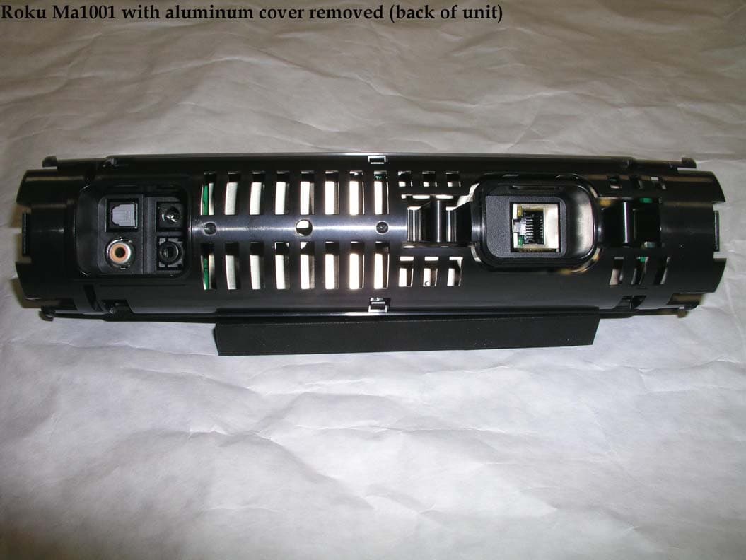
Click to zoom
Application Details
- Equipment Class
- DTS - Digital Transmission System
- Date of Grant
- Jul 18, 2005
- Application Purpose
- Original Equipment
- Date of Application
- Jul 18, 2005
- Equipment Note
- Network Music Player
- Frequency Range
- 2412.00000000 - 2462.00000000
- Company
- Roku, Inc.
- Country
- United States
Documents & Files
Document Text
Text extracted from the exhibit documents filed with the FCC. Open a document above to read the original.
Users Manual
User Guide | Software v 2.2 SoundBridge Network Music Player [inside front cover] Welcome Thanks for purchasing Roku SoundBridge! We hope you enjoy using it as much as we’ve enjoyed creating it. SoundBridge lets you play music you have stored on your PC or Mac anywhere in your home. It also lets you access many of the thousands of Internet radio stations that broadcast on the web without turning on your computer. Enjoy! Run the Latest Software! {#} Roku’s media players are designed to be upgradeable in the field, and we are always working on improving the software for our products. Your SoundBridge has a menu option to check for, and automatically install, software updates. We recommend you try this as soon as your system is set up to make sure you have the latest software. You can do it from the comfort of your couch, using the SoundBridge remote control. All you need is an active Internet connection. See “Checking for the Latest Software” on page 14 for easy instructions. Register Your SoundBridge! It’s quick, easy and allows you to receive the latest software updates for SoundBridge. Of course, we won’t share your personal information with anyone else. Download the Latest User Guide! When our software changes, so does our user guide. Visit www.rokulabs.com/support to download the latest version as a PDF document to learn about the latest features. Visit www.rokulabs.com/support to register your SoundBridge. TABLE OF CONTENTS Getting Started I. Music Server Software Requirements ..................3 II. Hooking Up Your Home Network Hardware (Wired Ethernet or Wireless) ....................................7 III. Hooking Up Your Speakers or Stereo System ...7 IV. Connecting SoundBridge to AC Power ...............9 V. Using Your Remote Control ......................................9 VI. Establishing a Network Connection ...................10 VII. Enabling Music Sharing ............................................12 VIII. Choosing Your Music Library .................................13 IX. Playing Music ...............................................................14 X. Setting Display Preferences (optional) ..............14 XI. Checking for the Latest Software (recommended) ..........................................................14 XII. Wall or Under-Cabinet Mounting (optional) ...15 Music Playback — Overview Audio File Formats Supported .........................................16 Navigation Quick Reference ..............................................16 Screen Icons Quick Reference ...........................................17 Music Playback — Tutorial The Home Menu .....................................................................18 Browsing by Album ...............................................................19 Building a Song Queue ........................................................20 Reviewing a Song Queue ....................................................22 Erasing a Song Queue .........................................................23 Repeat and Shuffle ................................................................23 Pausing Music Playback .......................................................23 Skipping Tracks During Playback ....................................24 Playing a Playlist .....................................................................24 Browsing by Artist, Song or Composer .........................25 Browsing by Genre ................................................................26 Search Options ........................................................................26 Changing Music Libraries ...................................................27 Internet Radio ..........................................................................27 Web Page Control ..................................................................31 When You Are Finished Using SoundBridge ...............37 Advanced Features Control Brightness, Contrast and Text Display ...........38 The Settings Menu ................................................................38 Music Visualizer Settings ....................................................38 Clock Settings ..........................................................................39 Language Setup .....................................................................41 Safe Mode .................................................................................42 Restoring Factory Default Settings .................................42 Geeks — Read This ................................................................42 Wi-Fi Setup and Password Help Wi-Fi Setup Examples Apple AirPort (Mac Users) ...........................................47 Apple AirPort (PC Users) ..............................................50 Linksys WAP54G .............................................................54 Netgear WG602 ...............................................................56 Customer Support ..............................................................59 Appendices End User Software License Agreement ........................60 iTunes Disclaimer ...........................................................60 Limited Warranty ...................................................................61 FCC Warnings and Safety Information ...........................63 European Community .......................................................66 Technical Specifications ..................................................67 3 GETTING STARTED To use SoundBridge you will need to: I. Make sure you have a compatible music server installed. Compatible music servers include iTunes, ® Microsoft ® Windows ® Media Connect, Rhapsody, ™ Musicmatch, ® and others. II. Connect SoundBridge Ethernet or Wi-Fi network hardware. III. Connect SoundBridge to powered speakers or your home stereo system’s receiver or amplifier. IV. Plug in SoundBridge to AC power (there is no “on/off” switch). V. Put batteries into your SoundBridge remote control. VI. Establish a netwo…
Text truncated - open the document above for the full version.
Cover Letter(s)
FCC ID: TC2M1001 D.L.S. ELECTRONIC SYSTEMS, INC. 1250 Peterson Drive Wheeling, Illinois 60090 FCC Authorization & Evaluation Division 7435 Oakland Mills Road Columbia, Maryland 21045-0429 Gentlemen: We are submitting for Roku, LLC, a SoundBridge M1001 Transmitter, Model Number: M1001, with a FCC ID: TC2M1001 for Certification. This unit has been tested and complies to Part 15, Subpart C. If there are any questions in regards to this application, please call D.L.S. Electronic Systems, Inc. at (847) 537 6400. Enclosed you will find a copy of our test report with the information and results of tests that is required under Part 15, Section 15.247. Thank you for your assistance in this matter. Sincerely, Arnom C. Rowe EMC-001375-NE DLS/sr
Cover Letter(s)
Letter of Agency Date: June 23, 2005 American Telecommunications Certification Body, Inc. 6731 Whittier Avenue Suite C110 McLean, VA 22101 To Whom It May Concern: Please be advised that Roku, LLC authorizes D.L.S. Electronic Systems, Inc. to act on our behalf, until otherwise notified, for applications submitted to American Telecommunications Certification Body, Inc. (ATCB). We certify that we are not subject to denial of federal benefits, that includes FCC benefits, pursuant to Section 5301 of the Anti-Drug Abuse ACT of 1988, U.S.C. 862. Further, no party, as defined in 47 CFR 1.2002(b), to the application is subject to denial of federal benefits, that includes FCC benefits. Thank you for your attention to this matter. Signatory, Arnom C. Rowe EMC ENGINEER EMC-001375-NE D.L.S. Electronic Systems, Inc. FCC Labeling Requirements and Information Date: June 23, 2005 American Telecommunications Certification Body, Inc. 6731 Whittier Avenue Suite C110 McLean, VA 22101 RE: FCC Labeling Requirements FCC ID: TC2M1001 The following label information is required by the FCC Rules and Regulations for certified devices. Also attached, please find marketing information required by the FCC Rules and Regulations. Thank you for your attention to these matters. Sincerely, Arnom C. Rowe EMC ENGINEER EMC-001375-NE D.L.S. Electronic Systems, Inc. Request for Confidentiality Date: June 23, 2005 American Telecommunications Certification Body, Inc. 6731 Whittier Avenue Suite C110 McLean, VA 22101 RE: Certification Application FCC ID: TC2M1001 Pursuant to 47 CFR Section 0.459 Roku, LLC understands that requests for non disclosure and confidential treatment is being made for the following information as stated under the Code of Federal Regulations Chapter 47, Part 0.459 and behalf of APPLICANT NAME: • Block Diagram • Schematics The above materials contain trade secrets, proprietary and technical information that would customarily be guarded from competitors under 47 CFR section 0.457(d)(2). Disclosure or publication of any portion of this company confidential material to other parties could cause substantial competitive harm and provide unjustified benefits for competitors. Roku, LLC understands that pursuant to 47 CFR section 0.457(d)(1)(ii) disclosure of the applicant and all accompanying documentation will not be made before the date of the grant. Thank you for your attention to this matter. Signatory Arnom C. Rowe EMC ENGINEER EMC-001375-NE D.L.S. Electronic Systems, Inc. Modification Letter Date: June 23, 2005 American Telecommunications Certification Body, Inc. 6731 Whittier Avenue Suite C110 McLean, VA 22101 RE: Certification Application FCC ID: TC2M1001 Please be advised that the following information is a list of modifications that will be included in the production process for the above-referenced equipment. Change 1: There were no modifications made during testing. Change 2: Change 3: Change 4: Change 5: Change 6: Change 7: Change 8: Change 9 Change 10: Thank you for your attention to this matter. Signatory Arnom C. Rowe EMC ENGINEER EMC-001375-NE D.L.S. Electronic Systems, Inc. Manufacturer’s Letter Date: June 23, 2005 American Telecommunications Certification Body, Inc. 6731 Whittier Avenue Suite C110 McLean, VA 22101 RE: Certification Application FCC ID: TC2M1001 To Whom It May Concern: Please be advised that the manufacturer will ensure that the above-referenced model will be manufactured in accordance with the FCC Rules and Regulations. Thank you for your attention to this matter. Signatory Arnom C. Rowe EMC ENGINEER EMC-001375-NE D.L.S. Electronic Systems, Inc.
Cover Letter(s)
June 28, 2005 Attn: Director of Certification Authority to Act as Agent On behalf, I appoint AmericanTCB to act as our agent in the preparation of this application for equipment certification. I certify that submitted documents properly describe the device or system for which equipment certification is sought. I also certify that each unit manufactured, imported or marketed, as defined in Industry Canada’s regulations will have affixed to it a label identical to that submitted for approval with this application. For instances where our authorized agent signs the application for certification on our behalf, I acknowledge that all responsibility for complying with the terms and conditions for certification, as specified by Nemko Canada Inc, still resides with: D.L.S. Electronic Systems, Inc. 1250 Peterson Drive Wheeling, Illinois 60090 Dated this ____28th____ day of ___June__, 2005. Agency Agreement Expiration Date: February 25, 2006 By: Arnom C. Rowe (Print name) Title: EMC Test Engineer, EMC 001375-NE On behalf of: Roku, LLD (Company Name) Telephone: 847-537-6400
External Photos
Company: Roku, LLC Product: SoundBridge M1001 FCC ID: TC2M1001 Date: June 10, 2005 Photo Description: Roku M1001 front Company: Roku, LLC Product: SoundBridge M1001 FCC ID: TC2M1001 Date: June 10, 2005 Photo Description: Roku M1001 front – with aluminum cover removed Company: Roku, LLC Product: SoundBridge M1001 FCC ID: TC2M1001 Date: June 10, 2005 Photo Description: Roku M1001 back Company: Roku, LLC Product: SoundBridge M1001 FCC ID: TC2M1001 Date: June 10, 2005 Photo Description: Roku M1001 back – with aluminum cover removed Company: Roku, LLC Product: SoundBridge M1001 FCC ID: TC2M1001 Date: June 10, 2005 Photo Description: Roku M1001 with side cover removed
ID Label/Location Info
TAR-1005 U01 MARK 1. 1:1 ( 23.9mm X 16.4mm / R0.5mm ) 2.: 3. 4. MARK *Scale : 1:1 ( 23.9mm X 16.4mm / R0.5mm ) *Material : Silver Polyester with Back Adhesive *printing color: Ground: Silver ( Raw material color ) Text and symbol: Black Label location: Left side opening recess
Internal Photos
Company: Roku, LLC Product: SoundBridge M1001 FCC ID: TC2M1001 Date: June 10, 2005 Photo Description: Roku M1001 front of PC board Company: Roku, LLC Product: SoundBridge M1001 FCC ID: TC2M1001 Date: June 10, 2005 Photo Description: Roku M1001 back of PC board with shield Company: Roku, LLC Product: SoundBridge M1001 FCC ID: TC2M1001 Date: June 10, 2005 Photo Description: Roku M1001 back of PC board (shield removed) Company: Roku, LLC Product: SoundBridge M1001 FCC ID: TC2M1001 Date: June 10, 2005 Photo Description: Roku M1001 antennas Company: Roku, LLC Product: SoundBridge M1001 FCC ID: TC2M1001 Date: June 10, 2005 Photo Description: Roku M1001 PC board back side of antennas
Operational Description
Description of how M1001 works: The M1001 is a networked music player. It operates by connecting to a networked storage device which contains a music server. The network connection can be either wired Ethernet or Wireless 802.11b. The M1001 will allow the user to select from multiple music servers. The M1001 has a VFD display which is driven from a serial shift register on the CPU. The CPU keeps the VFD display painted at all times. The M1001 has an IR sensor by which it receives IR commands that tell it what to do. When the user presses buttons on the IR remote, the M1001 will change the display accordingly. Once the user has selected a song or a list of songs to play from a server, then the M1001 will fetch the songs over the network. The songs are then decoded inside the CPU, and put out to the AC97 codec. The codec changes the digital codes back into analog and digital audio. A suitable stereo can be connected to the M1001 using analog line out, or digital coax SPDIF out, or digital optical SPDIF out. The transmitter on the M1001 is a 802.11b module that we purchase from Philips. The M1001 commands this device to transmit and receive using the SPI bus. The 802.11b module is connected to a 44MHz crystal, and the module connects to two antennas. One antenna is for receive only, and the other antenna is able to transmit and receive. The transmit/receive antenna signal has a low pass filter on it to stop harmonics of the 2.4GHz main transmit signal. The antennas used on the M1001 are chip antennas that mount directly to the PCB. There is ground plane next to the antenna. The traces that run from the Philips 802.11b module to the antenna are 50 Ohm traces.
RF Exposure Info
RF Exposure Exhibit for Roku TC2M1001 Mobile Devices are defined as a transmitting device designed to be used in other than fixed locations and to generally be used in such a way that a separation distance of at least 20 centimeters is maintained between the transmitter’s radiated structure(s) and the body of the user or nearby persons. Therefore, this device is classified under section 2.1091 as a “mobile” device. Although this device is categorically excluded from RF exposure evaluation under Part 2, it can be shown that the device meets the limits used for evaluating other devices (those which are not excluded) under this section. Section 2.1091 for mobile devices state that the limits are given in 1.1310. The limit given in 1.1310 for general population/uncontrolled at 2400 MHz is a Maximum Permissible Exposure (MPE) limit of 1 mW/cm 2 . The FCC OET Bulletin 65 Section 2 can be used to determine compliance with guidelines for human exposure to RF radiation. We will use equation 3 of that section for predicting RF fields. S = PG 4πR 2 S = power density (units e.g. mW/cm 2 ) P = power into to the antenna (or power output) (units e.g. mW) G = power gain of the antenna (worst case = 1) R = distance to the center of antenna (units e.g. cm) The highest power measurement for this device is 15.92 dBm. For this prediction we will use a worst-case power of 15.92 dBm or 39.0841 mW. Since the device is “portable”, we will use a worst-case distance of 20 cm. For worst-case antenna gain, we will use a gain of one. Using equation 3 of OET Bulletin 65 Section 2, the power density is calculated to be 0.007779476 mW/cm 2 . This is well within the limit given in 1.1310.
Test Report
1250 Peterson Dr., Wheeling, IL 60090 Company: Roku Model Tested: M1001 Report Number: 11433 FCC Rules and Regulations / Intentional Radiators Operational in the 902-928 MHz, 2400-2483.5 MHz, and 5725-5850 MHz, Bands Part 15, Subpart C, Section 15.247 THE FOLLOWING ''MEETS'' THE ABOVE TEST SPECIFICATION Formal Name: SoundBridge M1001 Kind of Equipment: Networked Music Player Test Configuration: Connected to stereo via analog RCA cables, and a SPDIF Digital RCA cable. Also connected via Ethernet to a computer with iTunes software running. (Tested at 120 vac, 60 Hz) Model Number(s): M1001 Model(s) Tested: M1001 Serial Number(s): 55D001008AH Date of Tests: May 11 and June 1 & 8, 2005 Test Conducted For: Roku 399 Sherman Palo Alto, California 94306 NOTICE: “This report must not be used by the client to claim product endorsement by NVLAP or any agency of the U.S. Government”. Please see the "Additional Description of Equipment Under Test" page listed inside of this report. This report must not be reproduced (except in full), without the approval of D.L.S. Electronic Systems. Page - 1 - 1250 Peterson Dr., Wheeling, IL 60090 Company: Roku Model Tested: M1001 Report Number: 11433 SIGNATURE PAGE Report By: Arnom C. Rowe Test Engineer EMC-001375-NE Reviewed By: William Stumpf OATS Manager Approved By: Brian Mattson General Manager Company Official: Roku Page - 2 - 1250 Peterson Dr., Wheeling, IL 60090 Company: Roku Model Tested: M1001 Report Number: 11433 Page -3 - 1250 Peterson Dr., Wheeling, IL 60090 Company: Roku Model Tested: M1001 Report Number: 11433 Page -4 - 1250 Peterson Dr., Wheeling, IL 60090 Company: Roku Model Tested: M1001 Report Number: 11433 Page -5 - 1250 Peterson Dr., Wheeling, IL 60090 Company: Roku Model Tested: M1001 Report Number: 11433 Page -6 - 1250 Peterson Dr., Wheeling, IL 60090 Company: Roku Model Tested: M1001 Report Number: 11433 Page -7 - 1250 Peterson Dr., Wheeling, IL 60090 Company: Roku Model Tested: M1001 Report Number: 11433 Page -8 - 1250 Peterson Dr., Wheeling, IL 60090 Company: Roku Model Tested: M1001 Report Number: 11433 Page -9 - 1250 Peterson Dr., Wheeling, IL 60090 Company: Roku Model Tested: M1001 Report Number: 11433 Page -10 - 1250 Peterson Dr., Wheeling, IL 60090 Company: Roku Model Tested: M1001 Report Number: 11433 Page -11 - 1250 Peterson Dr., Wheeling, IL 60090 Company: Roku Model Tested: M1001 Report Number: 11433 Page -12 - 1250 Peterson Dr., Wheeling, IL 60090 Company: Roku Model Tested: M1001 Report Number: 11433 Page -13 - 1250 Peterson Dr., Wheeling, IL 60090 Company: Roku Model Tested: M1001 Report Number: 11433 Page -14 - 1250 Peterson Dr., Wheeling, IL 60090 Company: Roku Model Tested: M1001 Report Number: 11433 Page -15 - 1250 Peterson Dr., Wheeling, IL 60090 Company: Roku Model Tested: M1001 Report Number: 11433 TABLE OF CONTENTS i. Cover Page.......................................................................................................................................1 ii. Signature Page.................................................................................................................................2 iii. NVLAP Certificate of Accreditation...............................................................................................3 iv. NVLAP Scope of Accreditation......................................................................................................4 v. Table of Contents...........................................................................................................................16 1.0 Summary of Test Report................................................................................................................18 2.0 Introduction....................................................................................................................................18 3.0 Object.............................................................................................................................................18 4.0 Test Set-Up....................................................................................................................................19 5.0 Test Equipment..............................................................................................................................20 6.0 Ambient Measurements.................................................................................................................21 7.0 Description of Test Sample............................................................................................................22 8.0 Additional Description of Test Sample..........................................................................................23 9.0 Photo Information and Test Set-Up...............................................................................................24 10.0 Radiated Photos Taken During Testing.........................................................................................25 10.0 Conducted Photos Taken During Testing......................................................................................27 11.0 Results of Tests..............................................................................................................................28 12.0 Conclusion.....................................................................................................................................28 TABLE 1 – EQUIPMENT LIST...............................................................................................................29 Page -16 - 1250 Peterson Dr., Wheeling, IL 60090 Company: Roku Model Tested: M1001 Report Number: 11433 TABLE OF CONTENTS Appendix A – Electric Field Radiated Emissions Test..............................................................................31 1.0 Conducted Emission Measurements..............................................................................................32 1.0 Conducted Data and Graph(s) taken during testing................…
Text truncated - open the document above for the full version.
Test Report
1250 Peterson Dr., Wheeling, IL 60090 APPENDIX A Company: Roku Model Tested: M1001 Report Number: 11433 TABLE OF CONTENTS 6.0 Field Strength of Spurious Emission Measurements.....................................................................66 6.0 Radiated Data and Graph(s) taken for Spurious Emission (Transmit Mode)................................69 6.0 Radiated Data and Graph(s) taken for Spurious Emission (Receive Mode) ...............................120 7.0 6 dB Bandwidth Graphs taken during testing..............................................................................145 7.0 Conducted Peak Output Power Graphs taken during testing.......................................................149 7.0 Peak Power Spectral Density Graphs taken during testing..........................................................153 7.0 Out-of-Band Emission Graphs taken during testing (2437 MHz)...............................................157 1250 Peterson Dr., Wheeling, IL 60090 APPENDIX A Company: Roku Model Tested: M1001 Report Number: 11433 6.0 FIELD STRENGTH OF SPURIOUS EMISSION MEASUREMENTS The radiated measurements made at D.L.S. Electronic Systems, Inc., for the SoundBridge M1001, Model Number: M1001, are shown in tabulated and graph form. Preliminary radiation measurements were performed at a 3 meter test distance with the limits adjusted linearly when required. The frequency range from 30 MHz to over 960 MHz, depending upon the fundamental frequency as stated in Part 15.33a, was automatically scanned and plotted at various angles. Measurements for the SoundBridge M1001 were made up to 26000 MHz, in accordance with Section 15.33a for Intentional Radiators with a fundamental frequency of 2400 MHz. For intentional radiators, the frequency range to be investigated is determined by the lowest radio frequency generated by the device without going below 30 MHz, up to at least the tenth harmonic of the highest fundamental frequency or 10 GHz, whichever is lower. At those frequencies where significant signals were detected, measurements were made over the entire frequency range specified in FCC Part 15, Subpart C, Section 15.247 at the open field test site, located at Genoa City, Wisconsin, FCC file number 31040/SIT. When required, levels were extrapolated from 10 meters to 3 meters using a linear extrapolation. All signals in the frequency range of 30 MHz to 2000 MHz were measured with a Biconical Antenna or tuned dipoles and from 200 MHz to 1000 MHz, a Log Periodic or Tuned Dipoles were used. From 1000 MHz to 25 GHz Horn Antennas were used. During the test the equipment was rotated and the antenna was raised and lowered from 1 meter to 4 meters to find the maximum level of emissions. In order to find maximum emissions, the cables were moved through all the positions the equipment would be expected to experience in the field. The EUT, peripheral equipment and cables were configured to meet the conditions in ANSI C63.4-2003, Clauses 6 & 8 and Clause 12.1.4. Tests were made with the receive antenna(s) in both the horizontal and vertical planes of polarization. In each case, the table was rotated to find the maximum emissions. As stated in Section 15.247(b) the allowed maximum peak output power of the transmitter shall not exceed 1 Watt. In any 100 kHz bandwidth outside these frequency bands (the power that is produced by the modulation products of the spreading sequence), the information sequence and the carrier frequency shall be either at least 20 dB below that in the 100 kHz bandwidth within the band that contains the highest level of the desired power. Attenuation below the general limits specified in 15.209 is not required. Page - 66 - 1250 Peterson Dr., Wheeling, IL 60090 APPENDIX A Company: Roku Model Tested: M1001 Report Number: 11433 6.0 FIELD STRENGTH OF SPURIOUS EMISSION MEASUREMENTS (CON’T) Field strength limits are at a distance of 3 meters. The emission limits shown are based on measurement instrumentation employing an average detector. Emissions radiated outside of the specified frequency bands, except for harmonics are attenuated by at least 50 dB below the level of the fundamental or to the general radiated emission limits in Section 15.209, whichever is the lesser attenuation. Preliminary radiated emission measurements were performed at a 3 meter test distance. The frequency range from 30 MHz to 1000 MHz was automatically scanned and plotted at various angles. For receivers the tests were performed according to the procedures of the FCC as stated in the ''Methods of Measurement of Radio-Noise Emissions for Low-Voltage Electrical and Electronic Equipment in the Range of 9 kHz to 40 GHz'' found in the American National Standards Institute, ANSI C63.4-2003, Clause 12.1. All preliminary data below 1000 MHz was automatically plotted using the ESI 26/ESI 40 Fixed Tuned Receiver. The data was taken using Peak, Quasi-Peak or the Average Detector Functions as required. This information was then used to determine the frequencies of maximum emissions. Above 1000 MHz, final data was taken using the Average Detector. Below 1000 MHz, final data was taken using the ESI 26/ESI 40 Fixed Tuned Receiver. These plots were made using the Peak or Quasi-Peak Detector functions, with manual measurements performed on the questionable frequencies using the Quasi-Peak or the Average Detector Function of the Analyzer or ESI 26/ESI 40 Receiver as required. Above 1000 MHz, final data was taken using the Peak Detector on the Spectrum Analyzer. The bandwidths used are specified by the FCC as stated in the American National Standards Institute, ANSI C63.4-2003, Clause 4.2. From 150 kHz to 30 MHz a bandwidth of 9 or 10 kHz was used and from 30 MHz to 1000 MHz a bandwidth of 120 kHz and above 1000 MHz, a bandwidth of 1 MHz was used. Page - 67 - 1250 Peterson Dr., Wheeling, IL 60090 APPENDIX A Company: Roku Model Tested: M1001 Report Number: 11433 6.0 FIELD STRENGTH OF SPURIOUS EMISSION MEASUREMENTS (CON’T) The allow…
Text truncated - open the document above for the full version.
Contact Information
Applicant
Robert Curtis(VP Engineering)
Technical Contact
D.L.S. Electronic Systens, Inc.Arnom Rowe
[email protected]847-537-6400
1250 Peterson Drive · Wheeling, Illinois · United States
Test Firm
DLS Electronic Systems, Inc.William Stumpf
Technical Specifications
| # | Rule Parts | Frequency Range | Power Output |
|---|---|---|---|
| 1 | 15C | 2.41 GHz - 2.46 GHz | 39.00 mW |
Other Applications from Roku, Inc.
TC2-R1053
Aug 03, 2026Enhanced Voice Remote
Equipment Class
DTS - Digital Transmission SystemTC2-R1050
Sep 23, 2024Streaming Player
Equipment Class
DSS - Part 15 Spread Spectrum Transmitter
TC2-R1043
Nov 19, 2023Streaming Player with Built-in Speaker
Equipment Class
DTS - Digital Transmission System
TC2-R1040
Apr 12, 2021Set-top-box
Equipment Class
NII - Unlicensed National Information Infrastructure TX
TC2-R1039
Nov 22, 2020Remote Control
Equipment Class
NII - Unlicensed National Information Infrastructure TX