TDBVSN240VSN 240 Wireless Sensor & Repeater
Sensys Networks, Inc.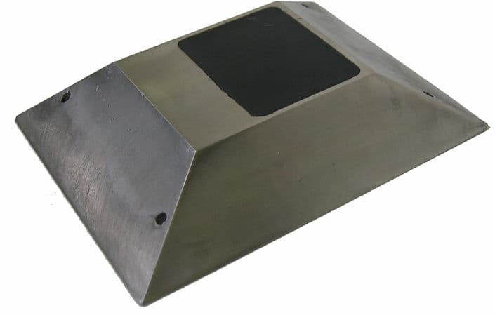
Click to zoom
Application Details
- Equipment Class
- DTS - Digital Transmission System
- Date of Grant
- Jan 02, 2006
- Application Purpose
- Original Equipment
- Date of Application
- Jan 02, 2006
- Equipment Note
- VSN 240 Wireless Sensor & Repeater
- Frequency Range
- 2405.00000000 - 2480.00000000
- Company
- Sensys Networks, Inc.
- Country
- United States
Documents & Files
Document Text
Text extracted from the exhibit documents filed with the FCC. Open a document above to read the original.
Users Manual
VSN240 Sensor Installation and User Manual Rev S-00001-20051010-1 Page 2 of 15 Contents Contents............................................................................................................... 2 1 Overview....................................................................................................... 3 RF Specifications...................................................................................................3 Physical Specifications ..........................................................................................3 Durability................................................................................................................3 Environmental........................................................................................................3 2 Package Contents......................................................................................... 4 3 Installation..................................................................................................... 5 3.1 Label Location and Information .............................................................................5 3.2 VSN240-F Install....................................................................................................5 Required Equipment:.............................................................................................6 Sensor Location and Orientation...........................................................................6 Coring Bits .............................................................................................................6 Installation Procedure............................................................................................7 3.3 VSN240-S Install....................................................................................................8 Required Equipment..............................................................................................8 Sensor Location and Orientation...........................................................................9 Metal Brush............................................................................................................9 Installation Procedure............................................................................................9 4 Using the SmartStud Adhesive................................................................... 11 Required Material.................................................................................................11 Adhesive Tube Integrity Check............................................................................11 Attach Mixing Nozzle and Flow Meter .................................................................11 Adhesive Applicator.............................................................................................12 5 Configuration and Integration...................................................................... 13 Overview..............................................................................................................13 An Example..........................................................................................................13 6 Support and Warranty Information.............................................................. 14 7 Communications Regulation Information .................................................... 15 FCC Compliance Statement................................................................................15 RF Exposure Statement.......................................................................................15 Rev S-00001-20051010-1 Page 3 of 15 1 Overview Congratulations for purchasing your Wireless Magnetic Sensor. This manual will support the installation of both in-pavement and surface mount models of the sensor, VSN240-F and VSN240-S respectively. The sensors use deviations in the earth’s magnetic field along three axes, to determine the presence or absence of a vehicle at the sensors location. Event information is then wirelessly transmitted back to an Access Point, AP240, which is responsible for analysis and further reporting. RF Specifications • IEEE 802.15.4 Standard Compliant Radio • 2.4 GHZ ISM Band Physical Specifications Table 1 VSN240-S Measure Metric US Length (L) 13.9 cm 5.35 inches Width (W) 9.2 cm 3.6 inches Height (H) 2.2 cm 0.9 inches Table 2 VSN240-F Measure Metric US Length (L) 7.4 cm 2.9 inches Width (W) 7.4 cm 2.9 inches Height (H) 4.9 cm 1.9 inches Durability • VSN240-F – Expected lifetime of 8 to 11 years, depending on traffic volumes. • VSN240-S – Expected lifetime of 5 to 7 years, depending on traffic volumes. Environmental • Nema 6P / IP 68 • Temperature Range: -40°C to +80°C Rev S-00001-20051010-1 Page 4 of 15 2 Package Contents Each VSN240 comes with the items found in the list below. If any of the contents is missing, contact customer service at [email protected]. • VSN240 Installation and Users manual. • The sensor itself (sealed and ready for installation). • An information sheet specifying the information below: o Senor ID (In hexadecimal format). o Operating Channel o Time Slot Assignment o Software Release Version o Board Rev Number o Battery Age o System Certification Checks. o Initials of System test Engineer. NOTE: If the new sensor has an identical slot number as another sensor in the same location, see the section on Changing Slot Numbers, in the VDS240 Wireless Vehicle Detection System Users Guide. Rev S-00001-20051010-1 Page 5 of 15 3 Installation NOTE: Sensys Networks is exempt from all responsibility of damage and injury caused by the installation or improper installation of either of the VSN240-F or VSN240-S sensors. Sensys Networks can recommend a “best method” of installation based on lab testing and field experience. It is at the discretion of the customer to choose how the installation will proceed. The recommended installation of the flush mount sensors is very different from the recommended …
Text truncated - open the document above for the full version.
Block Diagram
Exhibit 3 Block Diagrams VSN240 RP240
Block Diagram
Electromagnetic Compatibility Sensys Networks Equipment Configuration CFR Title 47, Part 15, Subpart C MET Report: EMCS18028-FCC247 © 2005, MET Laboratories, Inc. Page 8 of 57 Figure 2. Block Diagram of Test Configuration (Conducted measurements)
Block Diagram
Exhibit 3 Block Diagrams VSN240 RP240
Cover Letter(s)
Attn: Reviewing Engineer Federal Communications Commission 7435 Oakland Mills Road Columbia, MD 21046 RE: LETTER OF AGENT AUTHORIZATION To Whom It May Concern: We, the undersigned, hereby authorize MET Laboratories, Inc. to act on our behalf in all matters relating to application for equipment authorization, including the signing of all documents relating to these matters. We also hereby certify that no party to the application authorized hereunder is subject to the denial of benefits, including FCC benefits, pursuant to Section 5301 of the Anti-Drug Abuse Act of 1988, 21 U.S.C.853(a). This agreement expires one year from the current date. Sincerely, October 13, 2005 _________________________________ Robert Kavaler
Cover Letter(s)
Attn: Reviewing Engineer Federal Communications Commission 7435 Oakland Mills Road Columbia, MD 21046 RE: CONFIDENTIALITY REQUEST FOR EUT VSN240 (RP240 under Modular Approval) Wireless Magnetic Sensor, FCC ID# TDB-VSN240 To Whom It May Concern: This letter serves as an official request for confidentiality under FCC Rule Section 0.459. We have requested that the schematic diagrams required to be submitted with this application be withheld from public review. The circuitry implements the proprietary Sensys Nanopower Protocol (SNP), and the schematics should never get into the possession of our competitors. Please contact me if there is any information you may need. Sincerely, October 13, 2005 ______________________________________ Robert Kavaler
Cover Letter(s)
Rev Page 1 of 5 Request for Limited Modular Approval Sensys Networks, Inc is requesting a Limited modular approval for our VSN240 sensor and RP240 products. The RP240 implements the exact same circuit design as the VSN240, minus the magnetic sensors. They also run different software images. Below we have addressed and adhered to seven of the eight requirements of the Modular application criteria. The request for a limited approval opposed to a complete modular approval comes in regards to the shielding of our products (see question 1). Sensys Networks will retain total control over the final installation of both the VSN240 and RP240, as they will be factory tuned, and be installed in completely self contained units. Installation of the modular component will never be done by the customer, therefore, full compliance of the end product is always ensured. The labeling of either product will incorporate a label on the outside cover, that will define that device contains FCCID TDB-VSN240. 1. The modular transmitter must have its own RF shielding. This is intended to ensure that the module does not have to rely upon the shielding provided by the device into which it is installed in order for all modular transmitter emissions to comply with Part 15 limits. It is also intended to prevent coupling between the RF circuitry of the module and any wires or circuits in the device into which the module is installed. Such coupling may result in non-compliant operation. The EUT complied with all FCC Part 15 limits without ANY shielding, because our product does not depend on shielding to keep us within the standardized limits. Either device, VSN240 and RP240 is a complete standalone device, with no opportunity for coupling. 2. The modular transmitter must have buffered modulation/data inputs (if such inputs are provided) to ensure that the module will comply with Part 15 requirements under conditions of excessive data rates or over-modulation. The VSN240 and RP240 have buffering in both the microprocessor and the radio. 3. The modular transmitter must have its own power supply regulation. This is intended to ensure that the module will comply with Part 15 requirements regardless of the design of the power supplying circuitry in the device into which the module is installed. The power supply for the transmitter does have its own power regulator. 4. The modular transmitter must comply with the antenna requirements of Section 15.203 and 15.204(c). The antenna must either be permanently attached or employ a “unique” antenna coupler (at all connections between the module and the antenna, including the cable). Any antenna used with the module must be approved with the module, either at the time of initial authorization or through a Class II permissive change. The “professional installation” provision of Section 15.203 may not be applied to modules. Both the VSN240 and RP240 utilize the same permanently attached antenna, which has been has been tested and passed all FCC limitations. 5. The modular transmitter must be tested in a stand-alone configuration, i.e., the module must not be inside another device during testing. This is intended to demonstrate that the module is capable of complying with Part 15 emission limits regardless of the device into which it is eventually installed. Unless the transmitter module will be battery powered, it must comply with the AC line conducted requirements found in Section 15.207. AC or DC power lines and data input/output lines connected to the module must not contain ferrites; unless they will be marketed with the module (see Section 15.27(a)). The length of these lines shall be length typical of actual use or, if that length is unknown, at least 10 centimeters to insure that there is no coupling between the case of the module and supporting equipment. Any accessories, peripherals, or support equipment connected to the module during testing shall be unmodified or commercially available (see Section 15.31(i)). It was tested in a stand alone configuration, with a battery (without any ferrites) providing DC power. 6. The modular transmitter must be labeled with its own FCC ID number, and, if the FCC ID is not visible when the module is installed inside another device, then the outside of the device into which the module is installed must also display a label referring to the enclosed module. This exterior label can use wording such as the following: “Contains Transmitter Module FCC ID: XYZMODEL1” or “Contains FCC ID: XYZMODEL1.” Any similar wording that expresses the same meaning may be used. The Grantee may either provide such a label, an example of which must be included in the application for equipment authorization, or, must provide adequate instructions along with the module which explain this requirement. In the latter case, a copy of these instructions must be included in the application for equipment authorization. The modular transmitter will be printed on the circuit board, and both the cases for the VSB240 and RP240 will have the necessary labeling. 7. The modular transmitter must comply with any specific rule or operating requirements applicable to the transmitter and the manufacturer must provide adequate instructions along with the module to explain any such requirements. A copy of these instructions must be included in the application for equipment authorization. For example, there are very strict operational and timing requirements that must be met before a transmitter is authorized for operation under Section 15.231. For instance, data transmission is prohibited, except for operation under Section 15.231(e), in which case there are separate field strength level and timing requirements. Compliance with these requirements must be assured Both devices are factory tuned, and require no special instructions. 8. The modular transmitter must comply with any applicable RF exposure requirements. For example, FCC Rules in Sections 2.1091, 2.1093 and specific Sections of …
Text truncated - open the document above for the full version.
Cover Letter(s)
DOC-FCC009 4/14/2005 Page 1 of 2 FEDERAL COMMUNICATIONS COMMISSION - FCC FORM 731 APPLICATION FOR EQUIPMENT AUTHORIZATION Approved by OMB 3060 - 0934 Expires 02/28/2005 Item 1. Applicant's complete, legal business name: Sensys Networks, Inc. Item 2. Applicant's mailing address Line 1: 2560 Ninth Street, Suite 211 Line 2: P.O.Box: City: Berkeley State: CA Country (if foreign address): Zip/Postal Code: 94710 Item 3. FCC ID: TDBVSN240 Grantee code: TDB Equipment Product Code (14 characters maximum): Item 4. Person at the applicant's address to receive grant or for contact: First Name: Robert Last Name: Kavaler Telephone: 510-548-4620 Title: VP Engineering E-mail: [email protected] Fax No: 510-548-8264 Item 5. Instead of Applicant, the original Grant is authorized to be mailed to: Item 6. Technical Contact: Firm Name: Sensys Networks, Inc. Telephone: 510-548-4620 Fax No: 510-548-8264 First Name: Robert Middle Initial: A Last Name: Kavaler Address Line 1: 2560 Ninth Street, Suite 211 Address Line 2: City: Berkeley Country (if foreign address): Zip/Postal Code: 94710 E-mail: [email protected] Item 7. Non-Technical Contact: Firm Name: Sensys Networks, Inc. Telephone: 510-548-4963 Fax No: 510-548-8264 First Name: Amine Middle Initial: Last Name: Haoui Address Line 1: 2560 Ninth Street, Suite 211 Address Line 2: City: Berkeley Country (if foreign address): Zip/Postal Code: 94710 E-mail: [email protected] Item 8. * Does this application include a request for confidentiality for any portion(s) of the data contained in this application pursuant to 47 CFR § 0.459 of the Commission Rules? If "Yes" see instructions. (please mark as appropriate) M Yes Ο No Item 9. Does the applicant request that the Commission defer grant of this application pursuant 47 CFR § 0.457(d)(1)(ii)? No If so, specify date when grant may be issued (MM/DD/YYYY format): Item 10. * Equipment Class: DTS * Description of Product as it is Marketed: Wireless Magnetic Sensor (NOTE: This text will appear below the equipment class on the grant) Item 11. * Application is for: (please mark as appropriate) M Original Equipment (See instructions) Ο Change in identification of presently authorized equipment: Original FCC ID: Grant Date (MM/DD/YYYY format): Ο Class II permissive change or modification of presently authorized equipment (See instructions) Item 12. Is the equipment in this application: * (a) a composite device subject to an additional equipment authorization? * (b) part of a system that operates with, or is marketed with, another device that requires an equipment authorization? If either of the above questions is answered "Yes" complete section 12(c). Ο Yes M No Ο Yes M No (c) The related application: Ο has been granted under the FCC ID listed to the right Ο is in the process of being filed under the FCC ID listed to the right Ο is pending with the FCC under the FCC ID listed to the right FCC ID DOC-FCC009 4/14/2005 Page 2 of 2 Item 13. Name of test firm and contact person on file with the FCC, if different from applicant or contact person: Firm Name: MET Laboratories Last Name: Confroy First Name: Marie Address: 914 W. Patapsco Ave, Balto. MD 21230 Telephone: 410-354-3300 Ext: 412 Fax No.: 410-354-3313 E-mail: [email protected] Item 14. Enter any text that you would like to appear at the bottom of the Grant of Equipment Authorization. N/A Read each certification carefully before answering and signing this application Equipment Specifications: Rule Part Frequency Range (MHz) Power (W) Frequency Tolerance and Units Emission Designator Note Codes 15.247, Subpart C 2405 to 2480 MHz 1.4 mW +-40ppm WILLFUL FALSE STATEMENTS MADE ON THIS FORM ARE PUNISHABLE BY FINE AND IMPRISONMENT (U.S. CODE, TITLE 18, SECTION 1001), AND/OR REVOCATION OF ANY STATION LICENSE OR CONSTITUTION PERMIT (U.S. CODE, TITLE 47, SECTION 312(a)(1)), AND/OR FORFEITURE (U.S. CODE, TITLE 47, SECTION 503). Item 15. *SECTION 5301 (ANTI-DRUG ABUSE) CERTIFICATION: The applicant must certify that neither the applicant nor any party to the application is subject to a denial of Federal benefits, that include FCC benefits, pursuant to Section 5301 of the Anti-Drug Abuse Act of 1988, 21 U.S.C. § 862 because of a conviction for possession or distribution of a controlled substance. See 47 CFR 1.2002(b) for the definition of a "party" for these purposes. Does the applicant or authorized agent so certify? M Yes Ο No Item 16. APPLICANT/AGENT CERTIFICATION: I certify that I am authorized to sign this application. All of the statements herein and the exhibits attached hereto, are true and correct to the best of my knowledge and belief. IN accepting a Grant of Equipment Authorization issued by the FCC as a result of the representations made in this application, the applicant is responsible for (1) labeling the equipment with the exact FCC ID specified in this application, (2) compliance statement labeling pursuant to the applicable rules, and (3) compliance of the equipment with the applicable technical rules. If the applicant is not the actual manufacturer of the equipment, appropriate arrangements have been made with the manufacturer to ensure that production units of this equipment will continue to comply with the FCC's technical requirements. Authorizing an agent to sign this application, is done solely at the applicant's discretion; however, the applicant remains responsible for all statements in this application. If an agent has signed this application on behalf of the applicant, a written letter of authorization which includes information to enable the agent to respond to the above section 5301 (Anti-Drug Abuse) Certification statement has been provided by the applicant. It is understood that the letter of authorization must be submitted to the FCC upon request, and that the FCC reserves the right to contact the applicant directly at any time. * Signature of Authorized Person Filing: Marie Ann Confroy Title of authorized signature: TCB Administrator…
Text truncated - open the document above for the full version.
External Photos
Exhibit 7 External Photos Figure 1 VSN240-F Flush Mount Sensor Figure 2 VSN240-S Surface Mount Sensor
ID Label/Location Info
Exhibit 19 Label and Location
Internal Photos
The figure below represents a circuit board with an antenna, and one without. As one can see, there are no components located below/underneath the antenna.
Operational Description
Exhibit 2 Operational / Technical Description The circuit provides three main functions: general purpose micro-processor, rf transceiver and magnetic sensors. Each circuit has its own power supply and regulator, and corresponding filter and noise-reducing capacitors. The microprocessor controls the rf transceiver and the magnetic sensors. The microprocessor is a TI MSP430F149, the rf transceiver is a Chipcon CC2420 802.15.4 compliant transceiver in the 2.4 GHz ISM band. The magnetic sensors is a circuit made up of analog circuit components and Honeywell magnetic sensors. The devices start by listening on the RF transceiver for a packet from an access point device. Upon receiving this packet, the device starts sampling the magnetic sensors. The magnetic sensor data, either in raw format or processed format, is then transmitted by the device using the RF transceiver. The antenna is a ceramic patch antenna, loaded monopole antenna, or a slot antenna. In any case, one side of the PCB is ground, acting as the ground plane for the antenna. The unbalanced antenna output operates at 50 ohm impedance.
Operational Description
Description of Product as Marketed VSN240-s WIRELESS SENSOR VDS240 Wireless Vehicle Detection System In-Pavement Wireless Vehicle Sensor Measures Deviation of Earth’s Magnetic Field Traffic Count, Speed, Vehicle Presence & Type Freeways, Intersections, Parking Lots & Gates Rapid Deployment & Updates “Over the Air” The Sensys Networks VSN240-s is an in-pavement wireless vehicle sensor designed for both permanent and temporary deployment in all traffic conditions, from freeways to intersections to parking lots to gates. The VSN240-S detects vehicular traffic and reports it back to an AP240 access point. The VSN240-s measures the X, Y and Z components of the Earth’s magnetic field and analyzes these components to determine the presence or absence of a vehicle at its location. In a typical freeway count station application, one VSN240-s is deployed in each lane of traffic. Where individual vehicle speeds are desired, two VSN240-s devices can be deployed in each lane at a known distance from each other, typically 2m, in a manner similar to current inductive loop deployment. The VSN240-s can be glued, using a custom two-part adhesive, to the surface of the pavement similar to a raised pavement marker, or in regions where snow plow activity prohibits surface deployment, in a depression in the pavement or even buried under the pavement (see VSN240-f). Data Collection and Reporting The VSN240-s measures the Earth's magnetic field using a magneto resistive sensor, sampled at 128Hz. The VSN240-s automatically computes the “baseline” magnetic field (called “off”), and reports deviation of this field from this baseline at the presence of a vehicle (called “on”). The VSN240-s synchronizes its sample clock with the AP240, and therefore the data collected from one VSN240-s can be compared against another VSN240 to determine the length and the speed of a vehicle. There are three modes of operation: Event Mode, Data Mode, and Sleep Mode. The mode of operation and the parameters of operation can be selected from the AP240. In event mode, a sequence of off-on and on-off events is transmitted to the AP240 in a packet. The latency, number of events, minimum reporting interval, maximum reporting interval, synchronization of reporting, and other parameters are selectable via the AP240. In data mode, the actual output samples of the magnetic sensor are reported to the AP240. Reporting is performed in packets representing 125ms of data (16 samples) for the X, Y, and Z axes of the Earth’s magnetic field. In sleep mode, no data is reported to the AP240, saving power in the VSN240-s. Wireless Interface The VSN240-s implements the Sensys Nanopower Protocol, a TDMA protocol that allows for both high performance and long battery lifetime. Each VSN240-s is individually addressable, and transmits its data in a time-slot assigned by the AP240. Messages can be sent by the AP240 to set parameters on the VSN240-s, and to send commands to the VSN240-s such as changing its mode of operation. Up to 32 VSN240-s can operate on a single radio channel reporting with a minimum reporting interval of 125ms. More VSN240-s can be deployed by either using an additional AP240 on a different channel, or by increasing the minimum reporting interval. Another major feature of the VSN240-s is that its firmware can be updated “over the air” to ensure that the installed base of detectors can benefit from feature enhancements and software bug fixes. Recommended distances between an AP240 access point and the VSN240-s are as follows: AP240 Recommended Maximum AP240 to VSN240-f 12ft (4m) 75ft (25m) 18ft (6m) 105ft (35m) 24ft (8m) 150ft (50m) VNS240-s Dimensions: Length: 13.6 cm | 5.35 inches Width: 9.2 cm | 3.6 inches Height: 2.2 cm | 0.9 inches RF Specification IEEE 802.15.4 Standard Compliant Radio 2.4GHZ ISM Band Programmable Event Reporting Parameters Transmit Interval in seconds: 0.125, 0.25, 1, 2, 3, 5, 6 Reporting Latency in seconds: 0.125, 0.25, 0.5, 1, 2, 5, 10, 30 Durability Expected in-pavement lifetime of 5 to 7 years, depending on traffic volume. Environmental NEMA 6P / IP 68 Temperature: -40C to +80C ========================================================= VSN240-f WIRELESS SENSOR VDS240 Wireless Vehicle Detection System In-Pavement Wireless Vehicle Sensor Measures Deviation of Earth’s Magnetic Field Traffic Count, Speed, Vehicle Presence & Type Freeways, Intersections, Parking Lots & Gates Rapid Deployment & Updates “Over the Air” The Sensys Networks VSN240-f is an in-pavement wireless vehicle sensor designed for permanent deployment in all traffic conditions, from freeways to intersections to parking lots to gates. The VSN240-f detects vehicular traffic and reports it back to an AP240 access point. The VSN240-f measures the X, Y and Z components of the Earth’s magnetic field and analyzes these components to determine the presence or absence of a vehicle at its location. In a typical freeway count station application, one VSN240-f is deployed in each lane of traffic. Where individual vehicle speeds are desired, two VSN240-f devices can be deployed in each lane at a known distance from each other, typically 2m, in a manner similar to current inductive loop deployment. The VSN240-f is installed flush with the pavement surface in a 2” deep cored hole. Installation can be completed in less than 15 minutes. Data Collection and Reporting The VSN240-f measures the Earth's magnetic field using a magneto resistive sensor, sampled at 128Hz. The VSN240-f automatically computes the “baseline” magnetic field (called “off”), and reports deviation of this field from this baseline at the presence of a vehicle (called “on”). The VSN240-f synchronizes its sample clock with the AP240, and therefore the data collected from one VSN240-f can be compared against another VSN240-f to determine the length and the speed of a vehicle. There are three modes of operation: Event Mode, Data Mode, and Sleep Mode. The mode of operation and the parameters of operatio…
Text truncated - open the document above for the full version.
Parts List/Tune Up Info
Exhibit 18 Tune-up procedure over power range or at specific operating levels. Both the VSN240 and RP240 are factory tuned and aligned.
Test Report
MET Laboratories, Inc. Safety Certification - EMI - Telecom Environmental Simulation 33439 WESTERN AVENUE ! UNION CITY, CALIFORNIA 94587 ! PHONE (510) 489-6300 ! FAX (510) 489-6372 Electromagnetic Compatibility Criteria Test Report for the Sensys Networks Inc. Wireless Magnetic Sensor Verified under the FCC Certification Rules contained in Title 47 of the CFR, Part 15.247, Subpart C for Intentional Radiators MET Report: EMCS18028-FCC247 August 18, 2005 Prepared For: Sensys Networks Inc. 2560 Ninth Street, Suite 211 Berkeley, CA 94710 Prepared By: MET Laboratories, Inc. 33439 Western Ave. Union City, California 94587 Sensys Networks Inc. CFR Title 47, Part 15, Subpart C Wireless Magnetic Sensor 2.4 GHz ISM Band MET Report: EMCS18028-FCC247 © 2005, MET Laboratories, Inc. Page ii of vi Electromagnetic Compatibility Criteria Test Report for the Sensys Networks Inc. Wireless Magnetic Sensor Tested Under the FCC Certification Rules contained in Title 47 of the CFR, Part 15.247, Subpart C for Intentional Radiators Shawn McMillen, Project Engineer Cheryl Anicete Electromagnetic Compatibility Lab Documentation Department Engineering Statement: The measurements shown in this report were made in accordance with the procedures indicated, and the emissions from this equipment were found to be within the limits applicable. I assume full responsibility for the accuracy and completeness of these measurements, and for the qualifications of all persons taking them. It is further stated that upon the basis of the measurements made, the equipment tested is capable of operation in accordance with the requirements of Part 15.247, of the FCC Rules under normal use and maintenance. Tony Permsombut, Manager, Electromagnetic Compatibility Lab Sensys Networks Inc. CFR Title 47, Part 15, Subpart C Wireless Magnetic Sensor 2.4 GHz ISM Band MET Report: EMCS18028-FCC247 © 2005, MET Laboratories, Inc. Page iii of vi Report Status Sheet Revision Report Date Reason for Revision ∅ August 18, 2005 Initial Issue. Sensys Networks Inc. Table of Contents Wireless Magnetic Sensor 2.4 GHz ISM Band CFR Title 47, Part 15, Subpart C MET Report: EMCS18028-FCC247 © 2005, MET Laboratories, Inc. Page iv of vi Table of Contents I. Executive Summary .................................................................................................................................................1 A. Purpose of Test ...................................................................................................................................................2 B. Executive Summary ...................................................................................................…
Text truncated - open the document above for the full version.
Contact Information
Applicant
Robert Kavaler(VP Engineering)
Test Firm
MET LaboratoriesAlvin Ilarina
Technical Specifications
| # | Rule Parts | Frequency Range | Power Output |
|---|---|---|---|
| 1 | 15C | 2.40 GHz - 2.48 GHz | 1.40 mW |
Other Applications from Sensys Networks, Inc.
TDB-FLEX-RP
Sep 23, 2014FLEX RP Repeater
Equipment Class
DXX - Part 15 Low Power Communication Device Transmitter
TDB-MAG2
Aug 26, 2014MAG2/GR Sensor
Equipment Class
DXX - Part 15 Low Power Communication Device Transmitter
TDB-AP240E
Feb 20, 2006AP240-E, Wireless Sensor Device
Equipment Class
DTS - Digital Transmission System