TE4MPOD2-CAutomotive Diagnostic Scan Tool
Bright Star Engineering, Inc.
Click to zoom
Application Details
- Equipment Class
- DTS - Digital Transmission System
- Date of Grant
- Oct 03, 2012
- Application Purpose
- Original Equipment
- Date of Application
- Oct 03, 2012
- Equipment Note
- Automotive Diagnostic Scan Tool
- Frequency Range
- 2412.00000000 - 2462.00000000
- Country
- United States
Documents & Files
Document Text
Text extracted from the exhibit documents filed with the FCC. Open a document above to read the original.
Users Manual
ADDENDUM TO MICROPOD II USER MANUAL FCC Compliance Statements IC Compliance Statements RF Radiation Exposure and Hazard Statement To ensure compliance with RF exposure requirements, this device must be installed in a location such that the antenna of the device will be greater than 20 cm (8 in.) away from all persons. Using higher gain antennas and types of antennas not covered under the FCC/IC certification of this product is not allowed. Installers of the radio and end users of the product must adhere to the installation instructions provided in this manual. This device complies with Part 15 of the FCC Rules. Operation is subject to the following two conditions: (1) this device may not cause harmful interference, and (2) this device must accept any interference received, including interference that may cause undesired operation. In accordance with FCC 15.21, changes or modifications not expressly approved by the party responsible for compliance could void the user’s authority to operate the equipment. If necessary, the user should consult the dealer or an experienced radio/television technician for additional suggestions. The user may find the following booklet helpful: “Something About Interference.” This is available at FCC local regional offices. Our company is not responsible for any radio or television interference caused by unauthorized modifications of this equipment or the substitution or attachment of connecting cables and equipment other than those specified by our company. The correction will be the responsibility of the user. Use only shielded data cables with this system. This device has been designed to operate with an antenna having a maximum gain of 2 dB. Antenna having a higher gain is strictly prohibited per regulations of Industry Canada. The required antenna impedance is 50 ohms. Operation is subject to the following two conditions: (1) this device may not cause interference, and (2) this device must accept any interference, including interference that may cause undesired operation of the device. To reduce potential radio interference to other users, the antenna type and its gain should be so chosen that the equivalent isotropically radiated power (EIRP) is not more than that required for successful communication.
Users Manual
i microPod II User Guide Bright Star Engineering 299 Ballardvale Street, Suite 5 Wilmington, MA 01887 Tel: (978) 642-3200 Fax: (978) 642-3199 www.brightstareng.com ii iii Notice The information in this document is subject to change without notice. THE SOFTWARE AND DOCUMENTATION ARE PROVIDED "AS IS" WITHOUT WARRANTY OF ANY KIND INCLUDING WITHOUT LIMITATION, ANY WARRANTY OF MERCHANTABILITY OR FITNESS FOR A PARTICULAR PURPOSE. FURTHER, Bright Star Engineering DOES NOT, GUARANTEE, OR MAKE ANY REPRESENTATIONS REGARDING USE, OR THE RESULTS OF THE USE, OF THE SOFTWARE OR WRITTEN MATERIAL IN TERMS OF CORRECTNESS, ACCURACY, RELIABILITY, OR OTHERWISE. Restricted Rights Legend Use, duplication, or disclosure by the United States Government is subject to restrictions as set forth in subparagraph (c)(1)(ii) of the Rights in Technical Data and Computer Software clause at DFARS 252.227-7013. This document may not, in whole or in part, be copied, reproduced, translated, or reduced to any electronic medium or machine-readable form without prior consent, in writing, from Bright Star Engineering, Inc. Copyright 2012 Bright Star Engineering, Inc. All Rights Reserved Printed in the USA iv v Table of Contents Revision History .................................................................................................... 1 Getting Started with the Device ............................................................................ 2 Powering On...................................................................................................... 2 Connecting to the Device over USB .................................................................. 2 Device Overview ................................................................................................... 2 LED ................................................................................................................... 2 Configuring Device and Network Settings ............................................................. 3 Using the HTTP Interface .................................................................................. 3 System Settings ............................................................................................. 4 Network Settings ............................................................................................ 5 Wireless Settings ........................................................................................... 6 Manage Networks .......................................................................................... 8 Wireless Scan .............................................................................................. 11 TCP/IP over USB ......................................................................................... 12 Factory Defaults ........................................................................................... 13 Backup Settings ........................................................................................... 14 Software .............................................................................................................. 15 Software Upgrades .......................................................................................... 15 Using the HTTP Installer .............................................................................. 15 Recovering from a Failed Upgrade .............................................................. 16 Installing Applications ...................................................................................... 16 1 Revision History Revision Date Description 1.0 September 21, 2012 Initial release of platform documentation 2 Getting Started with the Device Powering On The device can be powered either by attaching to a vehicle or connecting a USB cable which is attached to a PC or USB power source. Verify the LED is illuminated GREEN. As soon as power is supplied to the device it will begin a boot sequence. The LED will blink RED during the boot phase. Once the device is booted into normal operational mode the LED will revert back to GREEN. Connecting to the Device over USB You should use a Windows PC that has the Bright Star Engineering CDCECM drivers installed. The drivers provide TCP/IP over USB capability to the Windows PC. Use a USB cable to connect the device to the PC. Once the device is booted you will be able to use an HTTP browser to connect to the device using the following URL: HTTP://172.22.22.22 The device configuration web site will appear. Device Overview LED The device has one LED which is capable of illuminating RED and GREEN. The following table describes the LED behavior when the device is in the designated state or mode. Power On When power is applied to the device the LED will illuminate GREEN for a brief period. BOOT When the system software initializes the LED will illuminate RED and blink at a moderate pace. RUNNING In a normal operating state the LED will illuminate GREEN. Note: If an application is running on the device, it has the ability to alter the behavior of the LED which may result in LED appearing in a differently. ERROR Under error conditions the LED will illuminate RED and blink at a very fast pace. S/W Upgrade During a software upgrade the LED will be illuminated READ and blink at a slow pace. RECOVERY If the device is unable to boot normally, an alternate system software configuration will be used. This is referred to as RECOVERY MODE. When running in this mode the LED will blink, alternating between RED and GREEN in a rapid pace. 3 Configuring Device and Network Settings Using the HTTP Interface Shown below is the main screen for the device configuration web site. The Overview page will provide you with version information for the hardware and software and the device serial number. 4 System Settings You can assign a name to the device that will be shown on the device discovery utility screen in place of the default serial number. You may also wish to set the date and time …
Text truncated - open the document above for the full version.
Cover Letter(s)
October 3, 2012 Product Name: MICROPOD II Automotive Diagnostic Scan Tool Model Number: MPOD2-C Bright Star Engineering, Inc. declares that the product listed above does not have provision to change country codes and these settings will be locked down in the factory. Sincerely, Roy Nachowitz Date: 10/3/12 Director of Operations 299 Ballardvale Street, Suite5 Wilmington, MA 01887 USA Tel: +1-978-642-3200 Fax: +1-978-642-3199 www.brightstareng.com
Cover Letter(s)
9/27/2012 Federal Communications Commission Equipment Authorization Branch 7435 Oakland Mills Road Columbia, MD 21046 Request for Confidentiality Company name: Bright Star Engineering, Inc. FCC ID: TE4MPOD2-C FCC Part 15 Certification Gentlemen, Pursuant to 47 CFR 0.457(d)(1)(ii) and 0.459 Bright Star Engineering, Inc. hereby requests permanent confidentiality of the following documents for the subject application: Exhibit Type File Name Description Schematics upod2_schematic Electrical schematics of MICROPOD2 Block Diagrams upod2_block_diagram Block diagrams of MICROPOD2 Operational Descriptions upod2_op_description Operational description of MICROPOD2 These documents contain detailed system, equipment description and related information about the product which Bright Star Engineering, Inc. considers to be proprietary, confidential, and a custom design otherwise not released to the general public. Since the design is a basis from which future technological products will evolve, Bright Star Engineering, Inc. considers that this information would be of benefit to its competitors and that the disclosure of the information in these documents would give competitors an unfair advantage in the market. Trade secret” information is information which is not generally known or reasonably ascertainable, by which a business can obtain an economic advantage over competitors. The information is not normally released to any party or person outside the company. The documents shown above are NOT publicly available. Sincerely, Signature: Name: Roy Nachowitz Title: Director of Operations Company: Bright Star Engineering, Inc. Address: 299 Ballardvale Street, Suite 5 Wilmington, Massachusetts 01887 299 Ballardvale Street, Suite5 Wilmington, MA 01887 USA Tel: +1-978-642-3200 Fax: +1-978-642-3199 www.brightstareng.com
Cover Letter(s)
Letter of Authorization Company: Bright Star Engineering, Inc. Address: 299 Ballardvale Street, Suite 5, Wilmington, MA 01887 Product Name: MICROPOD II Automotive Diagnostic Scan Tool Model Number: MPOD2-C We authorize MiCOM Labs, 440 Boulder Court, Suite 200, Pleasanton, CA 94566, USA, to act on our behalf on all matters concerning the above named equipment. Any individual within MiCOM Labs is authorized to act on our behalf and take action on the application. This shall include the following: Testing Approval applications and procedures Payment of approval fees We declare that MiCOM Labs, 440 Boulder Court, Suite 200, Pleasanton, CA 94566, USA, is allowed to forward all information related to the approval project to the applied notified body and to the notification entities and to discuss any issues concerning the approval application. Any and all acts carried out by MiCOM Labs on our behalf shall have the same effect as acts of our own. Name: Roy Nachowitz Date: 8/6/12 Title: Director of Operations Signature of applicant: 299 Ballardvale Street, Suite5 Wilmington, MA 01887 USA Tel: +1-978-642-3200 Fax: +1-978-642-3199 www.brightstareng.com
External Photos
MiCOM Labs, 440 Boulder Court, Suite 200, Pleasanton, CA 94566 Tel: +1 (925) 462-0304, Fax: +1 (925) 462-0306, Web: www.micomlabs.com the wireless lab 21 September 2012 Bright Star Engineering MPOD2-C External Photographs EUT Front Page 2 of 3 the wireless lab EUT Side Page 3 of 3 the wireless lab EUT Back
Internal Photos
MiCOM Labs, 440 Boulder Court, Suite 200, Pleasanton, CA 94566 Tel: +1 (925) 462-0304, Fax: +1 (925) 462-0306, Web: www.micomlabs.com the wireless lab 1 October 2012 Internal Photos Bright Star Engineering MPOD2-C The MPOD2-C consists of two PCB assemblies glued together. It was not possible to split the assemblies. Page 2 of 5 the wireless lab Page 3 of 5 the wireless lab Page 4 of 5 the wireless lab Page 5 of 5 the wireless lab
Test Report
COVER PAGE Test of Brig ht Star Engineering Inc. MicroPod MP OD2-C To: FCC 47 CFR Part 15.247 & IC RSS-210 Test Report Serial No.: BSTR39-U3 Rev B TITLE PAGE TEST REPORT FROM Test of Bright Star Engineering Inc. MicroPod MPOD2-C to To FCC 47 CFR Part 15.247 & IC RSS-210 Test Report Serial No.: BSTR39-U3 Rev B This report supersedes: BSTR39-U3 Rev A Applicant: Bright Star Engineering Inc 299 Ballardvale Street, Suite 5 Wilmington, MA 01887 USA Product F unction: Wireless Automobile OBDII Monitoring System Copy No: pdf Issue Date: 1st October 2012 MiCOM Labs is an ISO 17025 Accredited Testing Laboratory This Test Report is Issued Under the Authority of; MiCOM Labs, Inc. 440 Boulder Court, Suite 200 Pleasanton, CA 94566 USA Phone: +1 (925) 462-0 304 Fax: +1 (925) 462-0306 TEST CERTIFICATE #2381.01 www.micomlabs.com This test report may be reproduced in full only. The document may only be updated by MiCOM Labs personnel. Any changes will be noted in the Document History section of the report. Title: To: Serial #: Issue Date: Page: Bright Star Engineering Inc. MicroPod MPOD2-C FCC 47 CFR Part 15.247 & IC RSS-210 BSTR39-U3 Rev B 1st October 2012 3 of 109 This test report may be reproduced in full only. The document may only be updated by MiCOM Labs personnel. Any changes will be noted in the Document History section of the report. MiCOM Labs, 440 Boulder Court, Suite 200, Pleasanton, CA 94566 USA, Phone: 925.462.0304, Fax: 925.462.0306, www.micomlabs.com This page has been left intentionally blank Title: Bright Star Engineering Inc. MicroPod MPOD2-C To: Serial #: Issue Date: Page: FCC 47 CF R Part 15.247 & IC RSS-210 BSTR39-U3 Rev B 1st October 2012 4 of 109 This test report may be reproduced in full only. The document may only be updated by MiCOM Labs p ersonnel. Any changes will be noted in the Document History section of the report. MiCOM Labs, 440 Boulder Court, Suite 200, Pleasanton, CA 94566 USA, Phone: 925.462.0304, Fax: 925.462.0306, www.micomlabs.com TABLE OF CONTENTS ACCREDITATION, LISTINGS & RECOGNITION............................................................ 5 TESTING ACCREDITATION............................................................................................ 5 RECOGNITION................................................................................................................. 6 PRODUCT CERTIFICATION............................................................................................ 7 1. ................................................................................... 9 TEST RESULT CERTIFICATE 2. ........................................ 10 REFERENCES AND MEASUREMENT UNCERTAINTY 2.1. ............................................................................................. 10 Normative References 2.2. ............................................................................ 11 Test and Uncertainty Procedures 3. .......................................... 12 PRODUCT DETAILS AND TEST CONFIGURATIONS 3.1. ..................................................................................................... 12 Technical Details 3.2. ............................................................................................ 13 Scope of Test Program 3.3. ............................................................. 16 Equipment Model(s) and Serial Number(s) 3.4. ....................................................................................................... 16 Antenna Details 3.5. .............................................................................................. 16 Cabling and I/O Ports 3.6. ................................................................................................. 16 EUT Configurations 3.7. .................................................................................................. 17 Test Configurations 3.8. .................................................................................................... 17 Equipment Details 3.9. .......................................................................................... 19 Equipment Modifications 3.10. ..................................................................... 19 Deviations from the Test Standard 4. ........................................................ 20 TESTING EQUIPMENT CONFIGURATION(S) 4.1. ...................................................................... 20 Conducted RF Emission Test Set-up 4.2. .................................................. 21 Radiated Spurious Emission Test Set-up > 1 GHz 4.3. ......................................................... 22 Digital Emissions Test Set-up (0.03 – 1 GHz) 5. ...................................................................................................... 23 TEST SUMMARY 6. ........................................................................................................ 25 TEST RESULTS 6.1. ............................................................................................. 25 Device Characteristics 6.1.1. ...................................................................................25 Conducted Testing 6.1.2. ......................................................................87 Radiated Emission Testing 6.1.3. ........................102 AC Wireline Conducted Emissions (150 kHz – 30 MHz) 7. ..................................................................................................... 104 PHOTOGRAPHS 7.1. ......................................................... 104 Test Setup - Digital Emissions below 1 GHz 7.2. .................................................... 106 Test Setup - Spurious Emissions Above 1 GHz 8. ................................................................................................. 108 TEST EQUIPMENT Title: Bright Star Engineering Inc. MicroPod MPOD2-C To: Serial #: Issue Date: Page: FCC 47 CF R Part 15.247 & IC RSS-210 BSTR39-U3 Rev B 1st October 2012 5 of 109 This test report may be reproduced in full only. The do…
Text truncated - open the document above for the full version.
Test Setup Photos
MiCOM Labs, 440 Boulder Court, Suite 200, Pleasanton, CA 94566 Tel: +1 (925) 462-0304, Fax: +1 (925) 462-0306, Web: www.micomlabs.com the wireless lab 21 September 2012 Bright Star Engineering MPOD2-C TEST SETUP PHOTOGRAPHS Test Setup - Digital Emissions below 1 GHz Page 2 of 4 the wireless lab Page 3 of 4 the wireless lab Test Setup - Spurious Emissions Above 1 GHz Page 4 of 4 the wireless lab
Contact Information
Applicant
Roy Nachowitz(Director of Operations)
Technical Contact
Bright Star EngineeringRoy Nachowitz
[email protected](978)642-3212
299 Ballardvale Street · Wilmington · United States
Test Firm
Micom LabsGordon Hurst
Technical Specifications
| # | Rule Parts | Frequency Range | Power Output |
|---|---|---|---|
| 1 | 15C | 2.41 GHz - 2.46 GHz | 141.00 mW |
Other Applications from Bright Star Engineering, Inc.
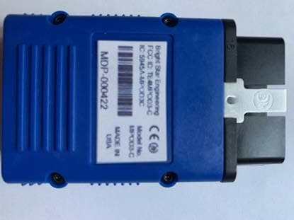
TE4MPOD3-C
Nov 01, 2020Automotive Diagnostic Tool
Equipment Class
DTS - Digital Transmission System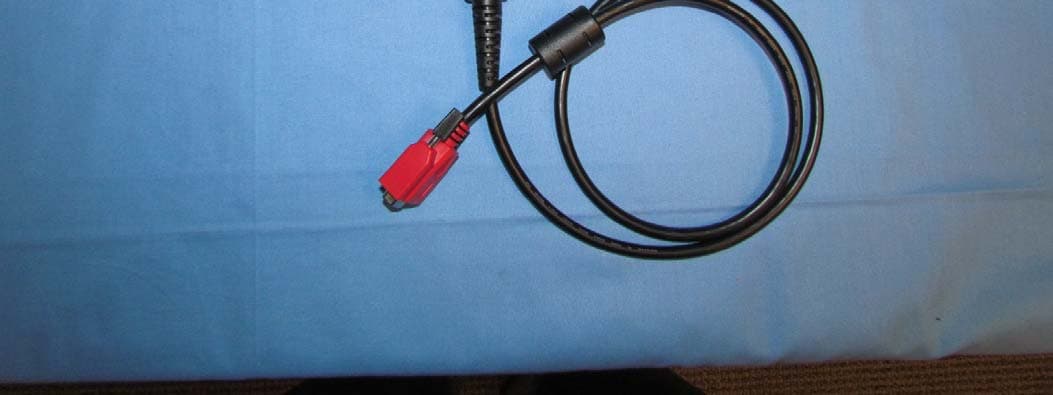
TE4WCB33
Mar 22, 2011Automotive Diagnostic Tool Cable
Equipment Class
DTS - Digital Transmission System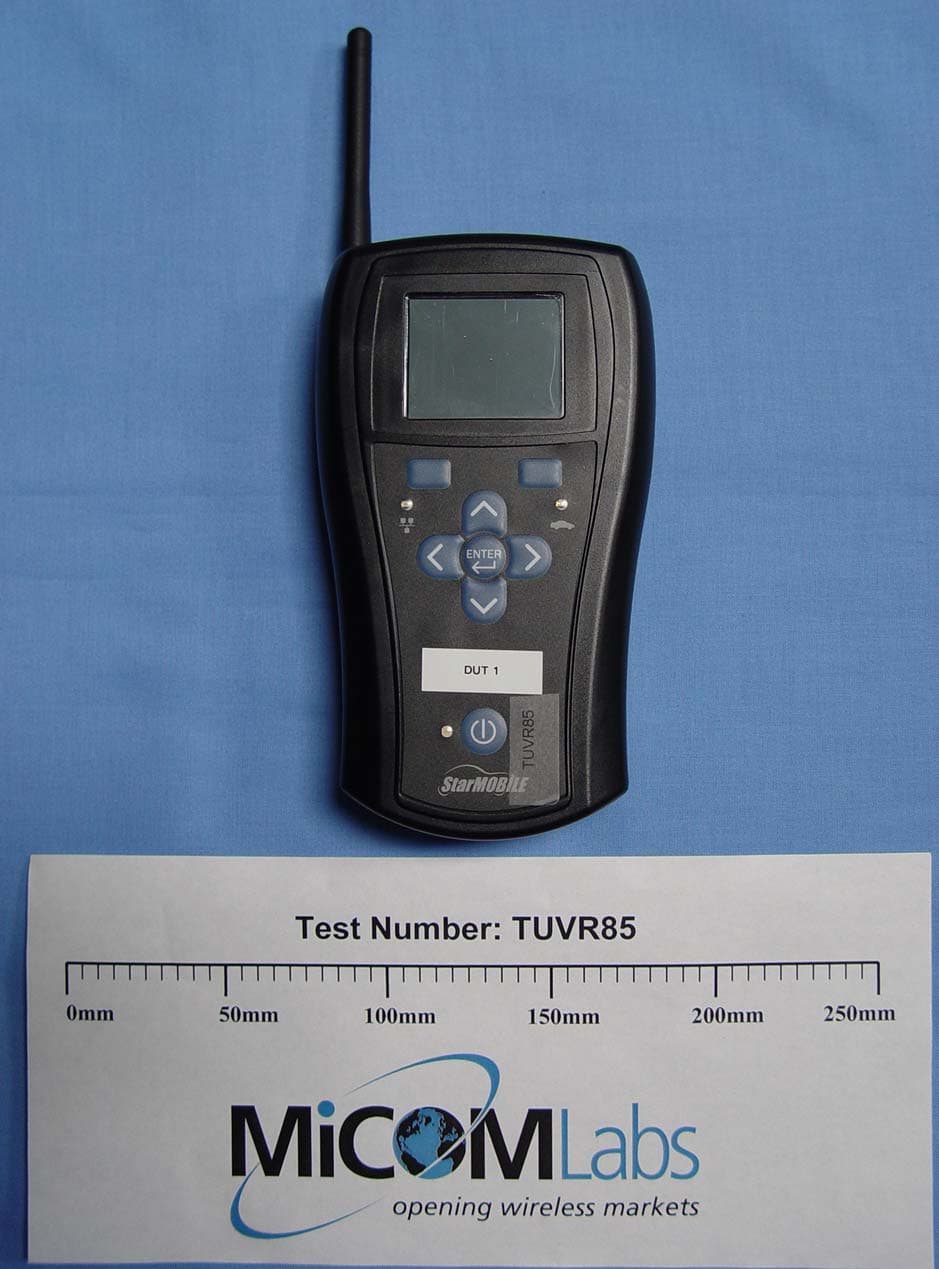
TE4CH9801
Jul 13, 2005Automotive Diagnostic Scan Tool
Equipment Class
DTS - Digital Transmission System