TGN-TCD8465Multimedia Hub
TiVo Solutions Inc. d/b/a TiVo Inc.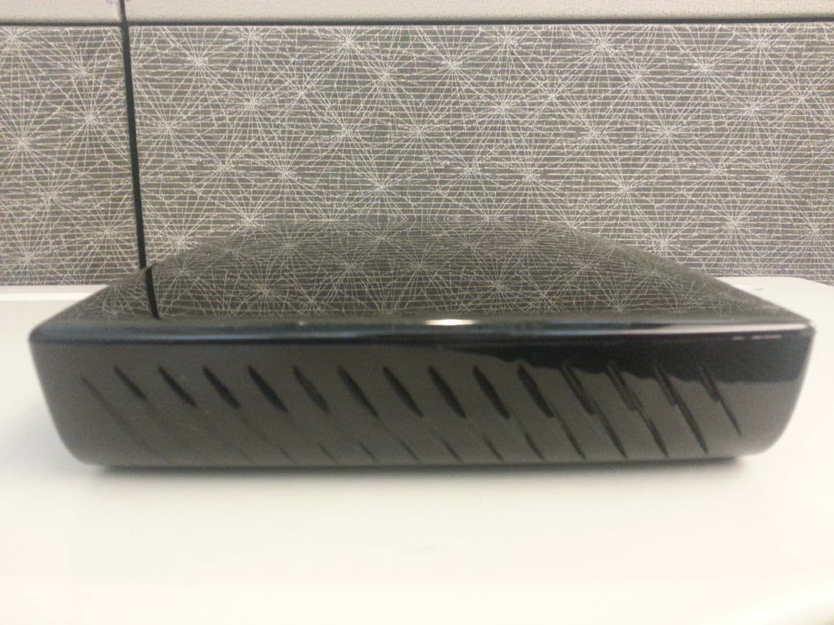
Click to zoom
Application Details
- Equipment Class
- DTS - Digital Transmission System
- Date of Grant
- Aug 06, 2013
- Application Purpose
- Original Equipment
- Date of Application
- Aug 06, 2013
- Equipment Note
- Multimedia Hub
- Frequency Range
- 2425.00000000 - 2475.00000000
- Country
- United States
Documents & Files
Document Text
Text extracted from the exhibit documents filed with the FCC. Open a document above to read the original.
Users Manual
Need some help? For more info on setting up or using your TiVo Roamio, see the Viewer’s Guide available online. tivo.com/howto CABLE / ANT DIGITAL AUDIO (OPTICAL) EXTERNAL STORAGE (E-SATA) COMPOSITEHDMIUSB POWER TiVo Inc. ETHERNET Complete Guided Setup Turn on your TV. After the TiVo Roamio starts up, you’ll see a Welcome screen. When you see the Welcome screen, you’re ready to begin Guided Setup. Just follow the on-screen instructions. You should complete Guided Setup even if you don’t yet have a CableCARD decoder. Note: If you don’t see the Welcome screen, use the Input, Source, or TV/Video button on your TV remote or TV to select the correct video input source. Once you’ve completed Guided Setup, turn this poster over to learn more about using your TiVo Roamio! 7 Plug in the power adapter The TiVo Roamio’s front panel displays a green light at startup. 6 Connect to your TV Connect an HDMI cable from the HDMI port of the TiVo box to the HDMI IN port on the back of your TV. If your TV does not have an HDMI port, see tivo.com/support for additional installation instructions. Television S-Video INPUT 3 HDMI 5 Connect to the cable service or antenna Connect the Coaxial RF cable coming from the wall, or connect the HDTV antenna, to the CABLE/ANT port on the back of the DVR. If this cable is connected to the TV or cable box, disconnect it and connect it to the TiVo DVR instead. 3 Ethernet (wired) – Connect an Ethernet cable from the TiVo DVR’s ETHERNET port to an open port on your router or to an Ethernet jack in your wall. MoCA (wired) – MoCA (Multimedia over Coax Alliance) gives you the same high-speed connection you get through a wired Ethernet cable, but it delivers it through your existing coax cable—the same cable you use to get cable TV. If you already have a MoCA network in your home, connect your TiVo Roamio to your MoCA network using a MoCA network adapter (available at tivo.com/store). If you don’t have a MoCA network yet, visit tivo.com/moca to learn how easy it is to get started. Connect to the Internet The TiVo Roamio needs a high-speed network connection to receive program listings, TiVo service updates, and on-demand content. The wired and wireless connection methods listed below are all sufficient for these purposes. However, if you plan to have multiple TiVo boxes in your home and would like to stream shows between them, or if you want to stream shows to your iPad ® or iPhone ® using the TiVo Stream (sold separately), you must use a wired connection (Ethernet or MoCA ® ). Choose one of the connection types below. (Don’t worry, you can always change this later.) Wireless – Use your DVR’s built-in wireless connection. You don’t need to connect any additional cables or adapters. 4 (To MoCA network adapter) Coaxial RF cable for receiving a cable signal and/or for connecting to the Internet through a MoCA network. Get to know your cables HDMI ® cable for high definition video and digital audio — recommended for HD setup. Power adapter (included). Ethernet cable for connecting to the Internet through a wired network if not using MoCA. Order a CableCARD decoder from your cable company (Skip this step if you use an HDTV antenna to receive TV.) If you receive cable TV from a cable provider, you’ll need a multi-stream CableCARD decoder to receive HD and digital cable channels. Order one Multi-Stream CableCARD (M-CARD) from your cable company and disconnect your digital cable box (if you have one). The M-CARD will replace your digital cable box. For CableCARD installation instructions, see the “Installing a CableCARD” insert that came with your TiVo Roamio. You don’t have to wait for your CableCARD to set up your TiVo Roamio. Continue to step 2. 1 2 CableCARD TM M-CARD Set up your TiVo ® Roamio in 7 easy steps. Welcome! Start Here Setting up your TiVo ® Roamio DVR is easy. Activate the TiVo ® service (if you haven’t already). The TiVo service is what makes your TiVo Roamio smart. It includes everything from your program listings to Season Pass ® recordings and WishList ® searches—all the cool features you’ve heard about. Some TiVo DVRs are sold with a TiVo service plan. If yours was not, activate the TiVo service at www.tivo.com/activate or call TiVo Customer Support at 1-877-367-8486. You’ll need your 15-digit TiVo Service Number (TSN), found on the label on the back of the Roamio. Write it here for reference ___________________________. About TV programming sources You can receive TV on your TiVo Roamio from a cable provider or from an HDTV antenna. For cable programming, the TiVo Roamio needs one Multi-Stream CableCARD TM decoder (M-CARD), available from your cable company. You don’t need to wait for your CableCARD decoder. Start connecting your TiVo Roamio now. You can install the CableCARD decoder later. For instructions, see the “Installing a CableCARD” insert that came with your TiVo Roamio. To get started connecting your TiVo Roamio, go to step 1. Start Here Follow these easy steps to connect your TiVo Roamio DVR Safety Instructions Save These Safety Instructions. Before you begin Make sure all your equipment is turned off and the TiVo DVR is unplugged. Your TiVo DVR is only capable of supporting the weight of one or two common A/V components such as VCRs, DVD players, or A/V receivers (provided they have four good, broad, padded feet that distribute of the weight near the corners of the TiVo DVR). Also, avoid stacking your TiVo DVR on top of other electronic components — such as DVD players, A/V receivers — or the vents of your TV. This product is for use only with listed ITE (Information Technology Equipment). Safety information This product was designed and manufactured to meet strict quality and safety standards. There are, however, some installation and operation precautions of which you should be particularly aware. Please read these instructions before operating the equipment and save them for future reference. 1. Read Instructions — All the safety and operating instruc…
Text truncated - open the document above for the full version.
Cover Letter(s)
TiVo Inc. Alviso | 2160 Gold Street, PO Box 2160 | Alviso, CA | 95002 | Phone (408) 519 -9100 | Fa x (408) 519-5 3 30 tivo.com New Yo r k | 150 E. 52nd Street, 15th Floor | New York, NY | 10022 | Phone (212) 520-1860 | Fax (212) 31 9 -5 074 June 7, 2013 National Technical Systems – Silicon Valley TCB 41039 Boyce Road Fremont, CA. 94538 Gentlemen: This is your letter of authorization to accept our appointment of National Technical Systems – Silicon Valley as our Agent for TiVo, Inc. 2160 Gold Street, PO Box 2160 Alviso CA. 95002, to sign applications before National Technical Systems – Silicon Valley TCB and to make representations to you on our behalf. National Technical Systems – Silicon Valley is to receive and exchange data between our company and National Technical Systems – Silicon Va l le y T C B. I hereby certify on behalf of TiVo, Inc. 2160 Gold Street, PO Box 2160 Alviso CA. 95002 (“Applicant”) that neither Applicant nor any party to the application (officers, directors, and 5% shareholders) is subject to a denial of Federal benefits that includes FCC benefits pursuant to section 5301 of the Anti-Drug Abuse Act of 1988. 21 U.S.C. 853a. Sincerely, Jim Inokuchi Manager Engineering Design Services TiVo Inc. | [email protected] | (408) 519-9253
Cover Letter(s)
TiVo Inc. Alviso | 2160 Gold Street, PO Box 2160 | Alviso, CA | 95002 | Phone (408) 519 -9100 | Fa x (408) 519-5 3 30 tivo.com New Yo r k | 150 E. 52nd Street, 15th Floor | New York, NY | 10022 | Phone (212) 520-1860 | Fax (212) 31 9 -5 074 June 14, 2013 Federal Communications Commission Authorization and Evaluation Division 7435 Oakland Mills Road, Columbia, MD 21046 Re: Request of Confidentiality for FCC ID: TGN-TCD8400 To Whom it May Concern: Pursuant to Sections 0.457 and 0.459 of the Commission’s Rules (CFR 47), and Section 552(b)(4) of the Freedom of Information Act, TiVo Inc. hereby requests confidentiality and treatment of certain information accompanying this application. The materials contain trade secrets and proprietary information not customarily released to the public. The public disclosure of these matters might be harmful to the Applicant and provide unjustified benefits to its competitors. We also hereby request Short-Term Confidentiality for 180 days after the grant as outlined in Public Notice DA 04-1705. This provision will give TiVo Inc. temporary confidentiality of commercially sensitive information prior to product release. The requested Permanent and Short-Term Confidential exhibits are listed as follows: PERMANENT AND SHORT-TERM CONFIDENTIAL LIST PeriodDescription Permanent Block Diagram Operational Description Schematics Short-Term All External, Internal and Test Setup Photos User’s Manual / Start Here Poster The Applicant understands that pursuant to Rule 0.457, disclosure of this application and all accompanying documentations, where applicable, will not be made public before the date of the Grant for this application. Sincerely Yours, Jim Inokuchi Manager, Engineering Design Services TiVo Inc.
Cover Letter(s)
Page 1 of 1 National Technical Systems – Silicon Valley TCB 41039 Boyce Road Fremont, CA. 94538 FCC ID: TGN-TCD8465 To whom it may concern: The enclosed documents constitute a formal submittal and application for Equipment Authorization for a Multimedia Hub that uses a RF4CE radio pursuant to the following rules: Subpart C of Part 15 of FCC Rules (CFR 47), Intentional Radiators The device also incorporates a WiFi module FCC ID: H8N-WLU5054. This device is also subject to the a Declaration of Conformity authorization as a computer peripheral and is labeled as such. National Technical Systems – Silicon Valley, as duly authorized agent prepared this submittal. A copy of the letter of our appointment as agent is included with the application. If there are any questions or if further information is needed, please contact National Technical Systems – Silicon Valley for assistance. Sincerely, David W. Bare Chief Engineer
RF Exposure Info
EMC Test Data Client: Contact: Standard: Test Specific Details General Test Configuration Yes, 13 6 cm Device complies with Power Density requirements at 20cm separation: Test Engineer: David Bare Calculation uses the free space transmission formula: S = (PG)/(4 πd 2 ) Where: S is power density (W/m 2 ), P is output power (W), G is antenna gain relative to isotropic, d is separation distance from the transmitting antenna (m). Summary of Results Maximum Permissible Exposure Objective: The objective of this test session is to perform final qualification testing of the EUT with respect to the specification listed above. Date of Test: 7/5/2013 Jim InokuchiProject Coordinator: - FCC Part 15BClass: N/A TivoJob Number: J90461 Model: TCD846500 T-Log Number: T90833 Project Manager: Sheareen Jacobs 13.6 cm - 20cm separation: If not, required separation distance (in cm): Modifications Made During Testing No modifications were made to the EUT during testing Deviations From The Standard No deviations were made from the requirements of the standard. T90833 Tivo.xlsMPE Calc 05-Jul-13Page 1 of 3 EMC Test Data Client: Contact: Standard: Jim InokuchiProject Coordinator: - FCC Part 15BClass: N/A TivoJob Number: J90461 Model: TCD846500 T-Log Number: T90833 Project Manager: Sheareen Jacobs Use: General Peak AveragedBmWWdBm 2412 - 2462 Module28.3-5.333.72.3231112.32333.66 2425 - 2475 EUT1.6-2.03.60.002310.0023.60 22.32533.66 Peak AveragedBmWWdBm 2425 - 2475 EUT1.6-2.03.60.002310.0023.60 5180 - 5240 Module17.0-6.323.30.214310.21423.30 20.21623.35 PeakAveragedBmWWdBm Band Output PowerAntenna gain (Max) EIRPChannels Available Totals: Totals: Band Output Power Channels Used Total EIRP Channels Used Total EIRP Antenna gain (Max) EIRPChannels Available Channels Used Total EIRP Band Output PowerAntenna gain (Max) EIRPChannels Available PeakAveragedBmWWdBm 2425 - 2475 EUT1.6-2.03.60.002310.0023.60 5260 - 5320 Module18.3-6.624.90.309310.30924.90 20.31124.93 Peak AveragedBmWWdBm 2425 - 2475 EUT1.6-2.03.60.002310.0023.60 5500 - 5700 Module18.1-6.724.80.302310.30224.80 20.30424.83 Channels Used Total EIRP Totals: Totals: Band Output PowerAntenna gain (Max) EIRPChannels Available gain (Max)AvailableUsed T90833 Tivo.xlsMPE Calc 05-Jul-13Page 2 of 3 EMC Test Data Client: Contact: Standard: Jim InokuchiProject Coordinator: - FCC Part 15BClass: N/A TivoJob Number: J90461 Model: TCD846500 T-Log Number: T90833 Project Manager: Sheareen Jacobs PeakAveragedBmWWdBm 2425 - 2475 EUT1.6-2.03.60.002310.0023.60 5725 - 5850 Module25.9-6.432.31.698511.69832.30 21.70132.31 Maximum From Above 0.4631.00013.6cm at 20 cmat 20 cmS <= MPE Limit mW/cm^2mW/cm^2cm Power Densit y MPE LimitDistance where Channels Available Channels Used Total EIRP Totals: Band Output PowerAntenna gain (Max) EIRP T90833 Tivo.xlsMPE Calc 05-Jul-13Page 3 of 3
Test Report
File: R92289 Rev 1 Page 1 EMC Test Report Application for Grant of Equipment Authorization Industry Canada RSS-Gen Issue 3 / RSS 210 Issue 8 FCC Part 15 Subpart C Model: TCD846500 FCC ID: TGN-TCD8465 APPLICANT: Tivo Inc. P.O. Box 2160 Gold Street Alviso, CA 95002-2160 TEST SITE(S): National Technical Systems - Silicon Valley 41039 Boyce Road. Fremont, CA. 94538-2435 IC SITE REGISTRATION #: 2845B-3; 2845B-4, 2845B-5, 2845B-7 REPORT DATE: June 12, 2013 REISSUE DATE: July 23, 2013 FINAL TEST DATES: May 2, 17, 20, 22 and 23, 2013 TOTAL NUMBER OF PAGES: 43 PROGRAM MGR / QUALITY ASSURANCE DELEGATE / TECHNICAL REVIEWER: FINAL REPORT PREPARER: ______________________________ ______________________________ David W. Bare David Guidotti Chief Engineer Senior Technical Writer National Technical Systems - Silicon Valley is accredited by the A2LA, certificate number 0214.26, to perform the test(s) listed in this report, except where noted otherwise. This report and the information contained herein represent the results of testing test articles identified and selected by the client performed to specifications and/or procedures selected by the client. National Technical Systems (NTS) makes no representations, expressed or implied, that such testing is adequate (or inadequate) to demonstrate efficiency, performance, reliability, or any other characteristic of the articles being tested, or similar products. This report should not be relied upon as an endorsement or certification by NTS of the equipment tested, nor does it represent any statement whatsoever as to its merchantability or fitness of the test article, or similar products, for a particular purpose. This report shall not be reproduced except in full National Technical Systems - Silicon Valley -- EMC Department Test Report Report Date: June 12, 2013 Reissue Date: July 23, 2013 File: R92289 Rev 1 Page 2 REVISION HISTORY Rev# Date Comments Modified By - 06-12-2013 First release 1 07-23-2013 Revised descriptive note for calculation of output power on Page 6 DWB National Technical Systems - Silicon Valley -- EMC Department Test Report Report Date: June 12, 2013 Reissue Date: July 23, 2013 File: R92289 Rev 1 Page 3 TABLE OF CONTENTS REVISION HISTORY ................................................................................................................................................ 2 TABLE OF CONTENTS ............................................................................................................................................ 3 SCOPE .......................................................................................................................................................................... 4 OBJECTIVE ................................................................................................................................................................ 5 STATEMENT OF COMPLIANCE ........................................................................................................................... 5 DEVIATIONS FROM THE STANDARDS .............................................................................................................. 5 TEST RESULTS SUMMARY ................................................................................................................................... 6 DIGITAL TRANSMISSION SYSTEMS (2400 – 2483.5MHZ) .............................................................................. 6 GENERAL REQUIREMENTS APPLICABLE TO ALL BANDS .......................................................................... 6 MEASUREMENT UNCERTAINTIES .................................................................................................................... 6 EQUIPMENT UNDER TEST (EUT) DETAILS ...................................................................................................... 7 GENERAL ................................................................................................................................................................ 7 ANTENNA SYSTEM .............................................................................................................................................. 7 ENCLOSURE ........................................................................................................................................................... 7 MODIFICATIONS ................................................................................................................................................... 7 SUPPORT EQUIPMENT ......................................................................................................................................... 7 EUT INTERFACE PORTS ...................................................................................................................................... 8 EUT OPERATION ................................................................................................................................................... 8 TEST SITE ................................................................................................................................................................... 9 GENERAL INFORMATION ................................................................................................................................... 9 CONDUCTED EMISSIONS CONSIDERATIONS ................................................................................................ 9 RADIATED EMISSIONS CONSIDERATIONS .................................................................................................... 9 MEASUREMENT INSTRUMENTATION ............................................................................................................ 10 RECEIVER SYSTEM ............................................................................................................................................ 10 INSTRUMENT CONTROL COMPUTER .............................................................…
Text truncated - open the document above for the full version.
Contact Information
Applicant
Joseph Lopez
Technical Contact
National Technical Systems - Silicon ValleyDavid Bare
[email protected]510-578-3500
41039 Boyce Road · Fremont, California · United States
Non-Technical Contact
National Technical Systems - Silicon ValleyDavid Guidotti
[email protected]510-578-3500
Test Firm
Element Materials Technology Fremont NewarkDavid Bare
Technical Specifications
| # | Rule Parts | Frequency Range | Power Output |
|---|---|---|---|
| 1 | 15C | 2.42 GHz - 2.48 GHz | 1.00 mW |
Other Applications from TiVo Solutions Inc. d/b/a TiVo Inc.
TGN-C00260
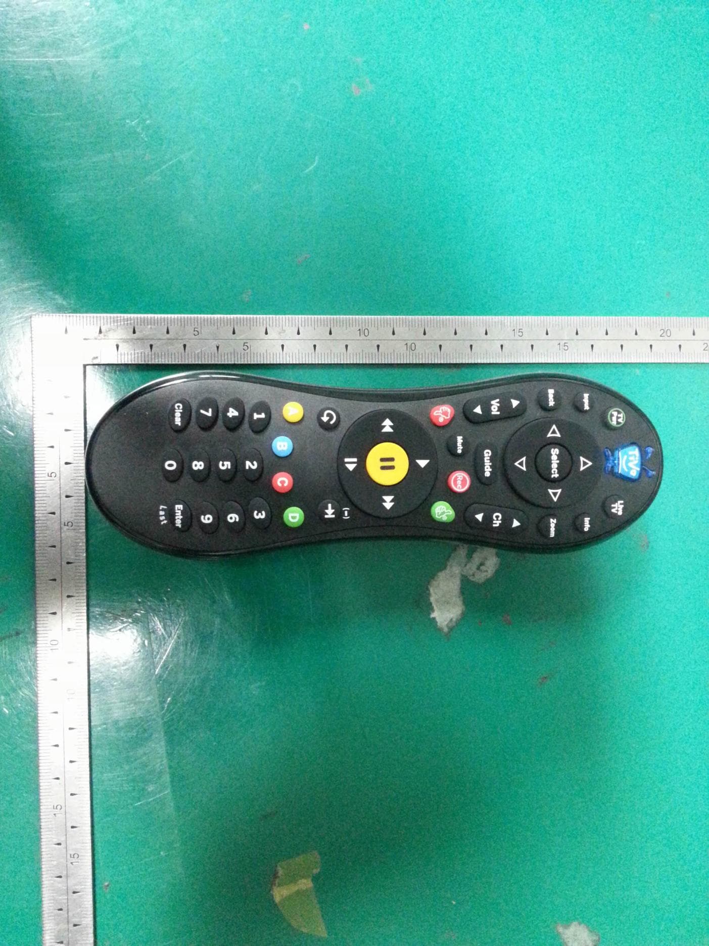
Oct 16, 2013IR & RF Remote Control
Equipment Class
DXX - Part 15 Low Power Communication Device Transmitter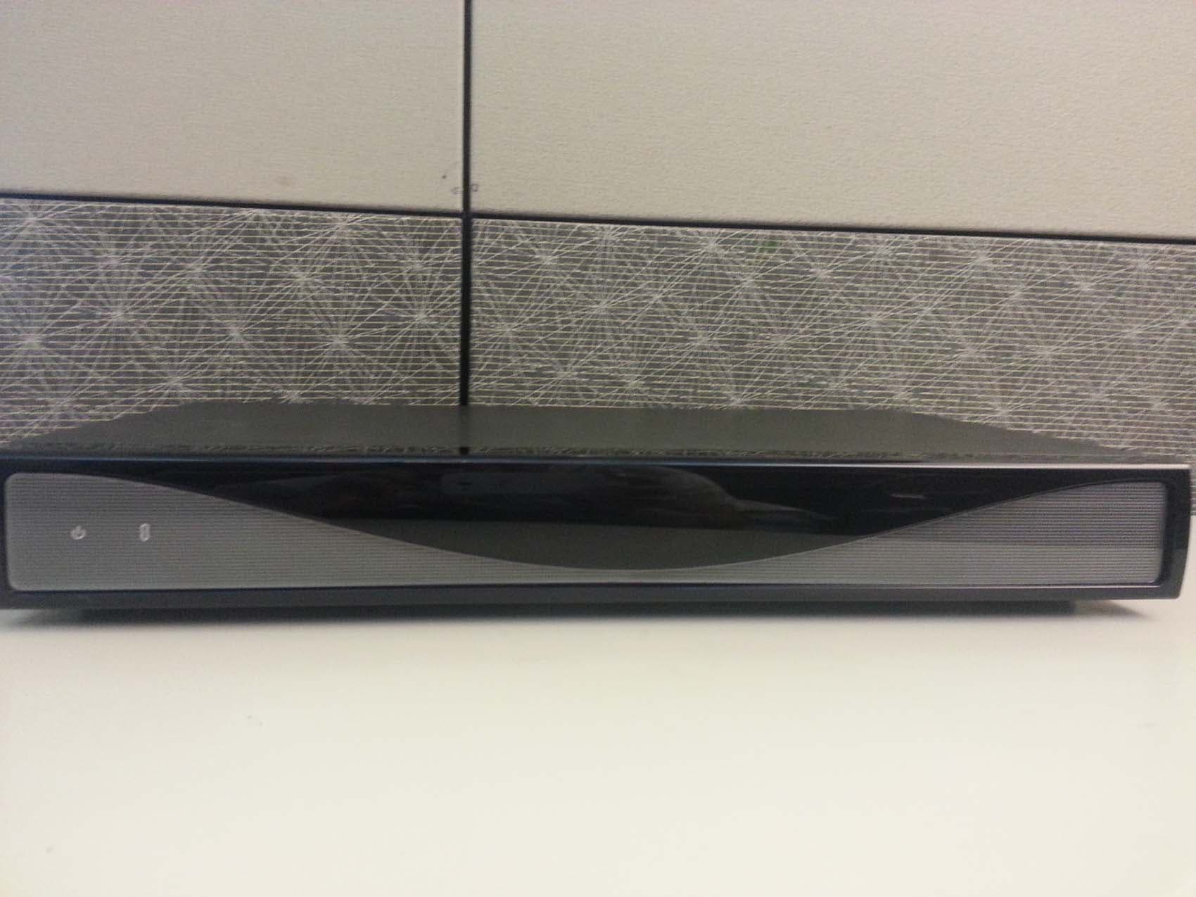
TGN-TCD8400
Aug 06, 2013Multimedia Hub
Equipment Class
DTS - Digital Transmission System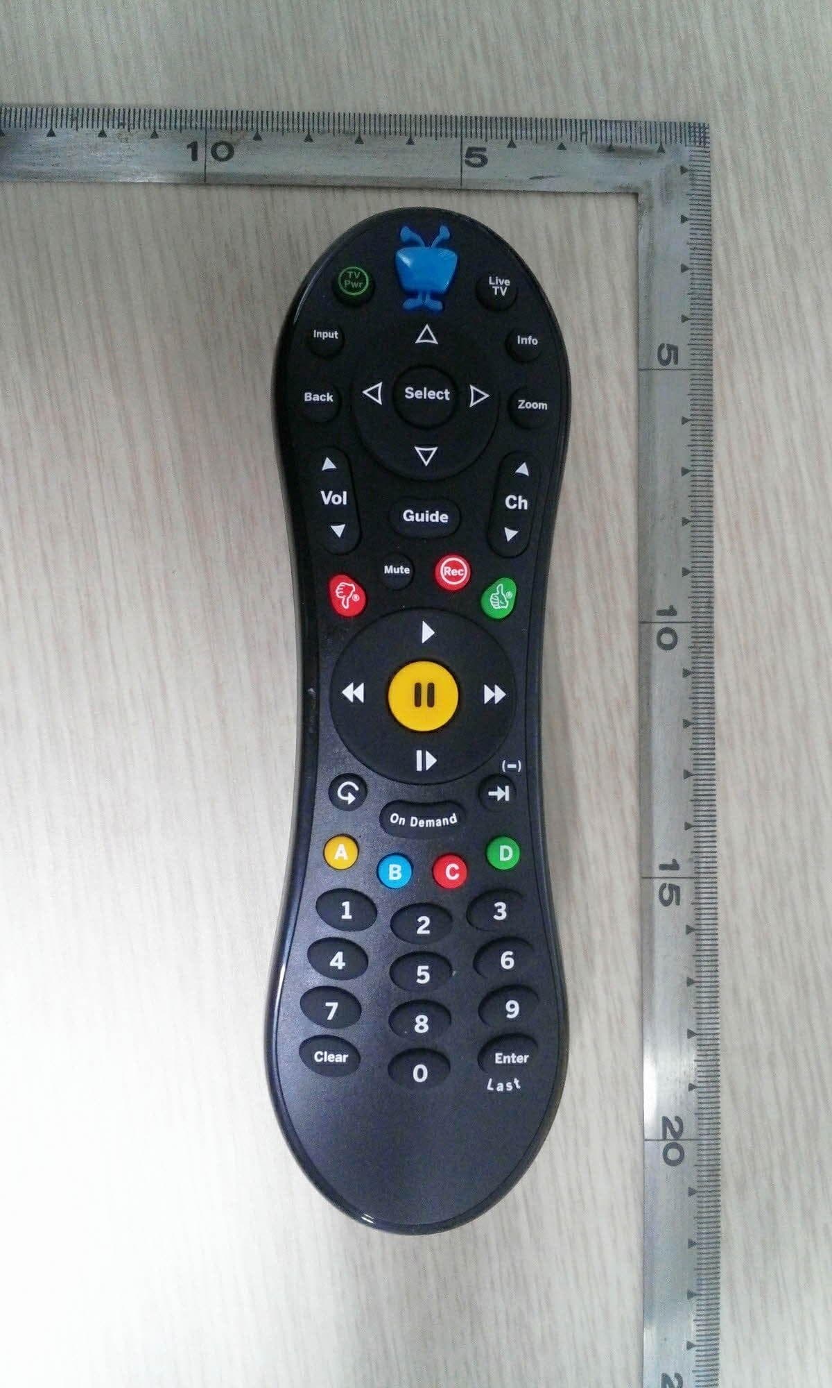
TGN-RC30
Jun 11, 2013IR&RF Remote Control
Equipment Class
DXX - Part 15 Low Power Communication Device Transmitter
TGN-C00240A
Jun 21, 2010TiVoSlide
Equipment Class
DSS - Part 15 Spread Spectrum Transmitter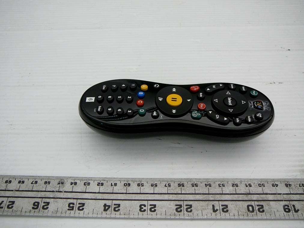
TGN-C00240
Jun 09, 2010Remote Control, Qwerty keyboard with Bluetooth
Equipment Class
DSS - Part 15 Spread Spectrum Transmitter