THCB19AC19� CCTV Monitor
D&T Inc.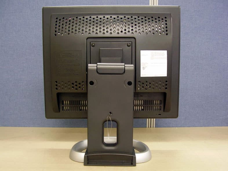
Click to zoom
Application Details
- Equipment Class
- JBP - Part 15 Class B Computing Device Peripheral
- Date of Grant
- Oct 17, 2005
- Application Purpose
- Original Equipment
- Date of Application
- Oct 17, 2005
- Equipment Note
- 19� CCTV Monitor
- Company
- D&T Inc.
- Country
- South Korea
Documents & Files
Document Text
Text extracted from the exhibit documents filed with the FCC. Open a document above to read the original.
Users Manual
User’s Guide H950V(B19AC) TFT-LCD Monitor Regulatory Information ............................ ......................... ......................... ......................... ........................ 2 Introduction Package ..................... ......................... ......................... ......................... ....................... ................ ................. 3 The range of control Angle ......... ......................... ...................... ...................... ...................... ........................3 Connection to Signal Source ...... ......................... ......................... ...................... ..................... ......................4 Controls Front panel ........................... ...................... ...................... ....................... ..................... .................. .............. 5 Functions ................... ......................... ......................... ......................... ....................... ................... ...............5 Adjusting OSD(PC MODE) .............. ......................... ...................... ....................... .................... ....................6 Adjusting OSD(CVBS, S-VIDEO MODE) ......................... ......................... ....................... .................... ....... 11 Caution .......................... ........................... ......................... ......................... ........................ ..........................16 Power Management Feature ......................... ......................... ......................... ...................... ................... 17 Standard Signal Table ........................... ......................... ......................... ......................... ......................... 18 Specifications ............................ ......................... ......................... ......................... ........................ .............. 19 Pin assignment table D-Sub Mini 15pin connector ............................ ......................... ...................... 20 Troubleshooting .......................... ............................ ......................... ......................... ....................... .......... 21 Table of Contents TFT-LCD Monitor 2 Regulatory Information - FCC Information Caution Changes or modifications not expressly approved by the party responsible for compliance could void the user’s authority to operate the equipment. - Canadian Notice This Class B digital apparatus meets all requirements of the Canadian Interference Causing Equipment Regulations. - Avis Canadien Cet appareil numérique de la classe B respecte toutes les exigences du Règlement sur le matériel brouilleur du Canada. - Energy Star As an ENERGY STAR partner, Hansol LCD Inc. has determined that this product meets energy Star guidelines for energy efficiency. Notice The information contained in this docum ent is subject to change without notice. This equipment has been tested and found to comp ly with limits for a class B digital device, pursuant to Part 15 of the FCC Rules. T hese limits are designed to provide reasonable protection against harmful interference in a residential installation.This equipment can generates, uses, and radiate r adio frequency energy and, if not installed and used in accordance with the instructions, may cause harmful interference to radio communications. However, there is no guarantee that interference will not oc cur in a particular installation. If this equipment does cause unacceptabl e interference to radio and television reception, which can be determined by turning the equipment off and on, the user is encouraged to try to correct the interference by one or more of the following measures. Reorient or relocate the receiving antenna. Increase the separation between the equipment and receiver. Connect the equipment into an outlet on a circuit diff erent from that to which the receiver is connected. Consult the dealer or an experienc ed Radio/TV technician for help. TFT-LCD Monitor 3 Introduction - Package - The range of control Angle LCD Monitor UKU.S.A/CanadaEuropeAustraliaKorea AC Power Cable Signal Cable C D(User’s Guide & etc) Warranty Card Congratulations on your purchase of this top quality color monitor!The items illustrated below are contained in the carton.First, be sure that your carton includes all of them.If any items are missing or damaged, please contact your local dealer or supplier. ▲ Forward 5 ° ▲ Default ▲ Backward 3 3 ° How to Adjust the Stand Stereo Cable(Option) TFT-LCD Monitor 4 Introduction - Connection to Signal Source <Power Source Connection> <Signal Cable Connection> ① ① Port for AC power cable . ② Port for BNC output. ③ Port for BNC input. ④ Port for S-VHS input. ⑤ Port for Audio input . ⑥ Kensington Lock. ⑦ Port for signal cable from signal source. ② ③ ④ ⑤ ⑥ ⑦ General For Macintosh Adapter for Macintosh(Optional) Refer to the table on the rear side of the optional Macintosh adapter and adjust DIP switch by the resolution. 1. Use 220V or 110 V. (Free Voltage)2. Connect monitor and Signal Source via Signal cable. 3. Power on the monitor and computer.4. Connection is finished. Basic Connection TFT-LCD Monitor 5 Controls - Front panel - Functions Power button Power button is located in the lower center of the Front Bezel. You can push the button to trun on/off the power. Power Indicating LED Dark : Power off Green : Normal mode Green blinking : DPMS mode or Check Signal Cable mode. On Screen Display(OSD) Function Button OSD buttons on the front of bez el perform the following functions. SOURCE : Monitor displa y s source of the signal in order (PC → CVBS → S-VHS) MENU/EXIT : Press this button to display menus.If you press this button when OSD is displayed, you can switch display to the previous menu and exit menu. SELECT/AUTO : Press this button, when OSD is not di splayed, to perform automati…
Text truncated - open the document above for the full version.
Users Manual
TFT-LCD Monitor 11 Controls - Adjusting OSD (CVBS, S-VIDEO MODE) Brightness / Contrast 1. Press the MENU button to access main menu.2. Use – , + to move Brig htness / Contrast ICON. 3. Press SELECT button into the submenu. Brightness Contrast 1. Use – , + to move Contrast ICON.2. Press SELECT button to select it.3. Use – , + to adjust the Contrast of the screen. 1. Use – , + to move Brightness ICON.2. Press SELECT button to select it.3. Use – , + to adjust the brightness of the screen. – + SELECT – + MENU – + SELECT – + SELECT – + Image 1. Press the MENU button to access main menu.2. Use – , + to move Image ICON.3. Press the SELECT button to go in the submenu. MENU – + SELECT MENU – + SELECT TFT-LCD Monitor 12 Aspect Ratio – + SELECT – + 1. Use – , + to move Aspect Ratio ICON. 2. Press the SELECT button to select it.3. Use – , + to select 4:3 or 5:4. Sharpness – + SELECT – + 1. Use – , + to move Sharpness ICON.2. Press SELECT button to select it.3. Use – , + to adjust the shrpness. (Adjust the clearness of the screen) Horizontal PositionVertical Position – + SELECT – + – + SELECT – + 1. Use – , + to move V-Position ICON.2. Press SELECT button to select it.3. Use – , + to adjust display upward or downward.1. Use – , + to move H-Position ICON. 2. Press SELECT button to select it.3. Use – , + to adjust display left or right. TFT-LCD Monitor 13 – + SELECT – + – + SELECT – + Color 1. Press MENU button to access main menu.2. Use – , + to move Color ICON.3. Press SELECT button into the submenu. HUE 1. Use – , + to select the HUE ICON.2. Press SELECT button to select it.3. Use – , + to adjust the HUE. Saturation 1. Use – , + to select the Saturation ICON.2. Press SELECT button to select it.3. Use – , + to adjust the saturation. MENU – + SELECT TFT-LCD Monitor 14 – + SELECT – + – + SELECT – + Preset Color – + MENU 1. Use – , + to select the Mode 1, and Mode 2. 2. Press the Menu button to re turn to the previous state. OSD 1. Press Menu button to access main menu.2. Use – , + to move OSD ICON.3. Press SELECT button into the submenu. OSD H-Position 1. Use – , + to move OSD H-Position ICON.2. Press SELECT button to select it.3. Use – , + to adjust OSD left or right. OSD V-Position 1. Use – , + to move OSD V-Position ICON.2. Press SELECT button to select it.3. Use – , + to adjust OSD upward or downward. 9300K : Slighty Bluish white. 6500K : Slighty Reddish white. MENU – + SELECT TFT-LCD Monitor 15 MENU – + SELECT – + SELECT OSD Time – + SELECT – + 1. Use – , + to move OSD Time ICON.2. Press SELECT button to select it.3. Use – , + to adjust OSD display time.4. Press Menu button to return main menu. Special 1. Press the MENU button to access main menu.2. Use – , + to move Special ICON.3. Press SELECT button into the submenu. Language 1. Use – , + to move the Language ICON.2. Press SELECT button to select it.3. Use – , + to select language. Factory Reset 1. Use – , + to move the Factory Reset ICON. 2. Press SELECT button to return to default setting. MENU – + SELECT – + TFT-LCD Monitor 16 Caution Information 1. Use – , + to move the Information ICON.2. Press SELECT button to select it. Sound 1. Use – , + to decrease or increase volume level.2. Press SELECT button to select it.3. Use – , + to control volume. MENU – + SELECT ※ You can know display information. According to the characteristic of video card, display information can be incorrect. MENU – + SELECT The lighting flash with arrowhead symbol,Within an equilateral trangle, is intended to alert the user to the presence of uninsulated"dangerous voltage" within the product's enclosure thatmay be of sufficient magnitud e to constitude a risk of electric shock to persons.The exclamation point within an equilateral trangle is intended to alert the user to the presence of important operating and maintenance (ser vicing) instructions in the literature accompan ying the appliance. CAUTION : TO REDUCE THE RISK OF ELECTRIC SHOCK DO NOT REMOVE COVER(OR BACK)NO USER-SERVICEABLE PARTS INSIDE.REFER SERVICING TO QUALIFIED SERVICE PERSONNEL TFT-LCD Monitor 17 Power Management Feature The monitor is equipped with a power saving circuit that confirms to t he world-standard Display Power Manager Signalling (DPMS) mode of Video El ectronics Standard Association(VESA). The power management feature requires that the video card of the comput er should support DPMS function. Status LED Sign Power Consumption Normal mode Green ON Normal Power DPMS mode Green Blinking 3W or Below DPMS with Audio Mute ON 3W or Below Mute OFF 5W or Below No image is displayed with Green blinking. Monitor is in power saving mode.Use mouse or keyboard to release power saving mode. No image is displayed without LED on. Power cable plug must be pulled out.Check the power plug on monitor and on the wall. "Out of range" displayed on the screen. This message is displayed when the si gnal from video card exceeds the maximum frequency of the monitor. Readjust resolution and frequency in accordance with the monitor capacity. (Refer to Standard Signal Table) TFT-LCD Monitor 18 Standard Signal Table Resolution Horizontal Frequency(kHz) Vertical Frequency(Hz) Clock Frequency (MHz) Sync Polarity (H/V) VGA (720 x 400) 31.469 70.087 28.322 - / + VGA (640 x 480) 31.469 59.940 25.175 - / - VGA (640 x 480) 37.500 75.000 31.500 - / - SVGA (800 x 600) 37.900 60.320 40.000 + / + SVGA (800 x 600) 46.875 75.000 49.500 + / + XGA (1024 x 768) 48.363 60.004 65.000 + / + XGA (1024 x 768) 60.023 75.029 78.750 + / + SXGA (1280 x 1024) 63.981 60.020 108.000 + / + SXGA (1280 x 1024) 79.976 75.025 135.000 + / + MAC (640 x 480) 35.000 66.667 30.240 - / - MAC (832 x 624) 49.726 74.551 57.284 - / - MAC (1152 x 870) 68.681 75.062 100.000 - / - PC Supported ModeDVR Supported Mode Resolution Horizontal Frequency(kHz) Vertical Frequency(Hz) Clock Frequency (MHz) Sync Polarity (H/V) NTSC 1 (616 x 452) 31.469 59.940 24.5454 - / - NTSC 2 (680 x 452) 31.469 59.940 27.000 - / - PAL 1 (736 x 544) 31.250 50.000 29.500 - / - PAL 2 (…
Text truncated - open the document above for the full version.
Block Diagram
AUDIO OSDCONTROLS
External Photos
CERTiTEK Standards Laboratory Co., Ltd. 386-1, Ho-Dong, Yongin-City, Kyungki-Do, Korea 449-100 Tel: +82-31-339-9970 Fax: +82-31-339-9855 http://www.certitek.com/ Test Report No.: 2005100015 Date: October 17, 2005 Page 19 of 25 This Report shall not be reproduced except in full without the written approval of CERTiTEK Form No.: CTK-FF2.0 CERTiTE K EUT External Photographs
ID Label/Location Info
CERTiTEK Standards Laboratory Co., Ltd. 386-1, Ho-Dong, Yongin-City, Kyungki-Do, Korea 449-100 Tel: +82-31-339-9970 Fax: +82-31-339-9855 http://www.certitek.com/ Test Report No.: 2005100015 Date: October 17, 2005 Page 24 of 25 This Report shall not be reproduced except in full without the written approval of CERTiTEK Form No.: CTK-FF2.0 CERTiTE K Photographs related to Label CERTiTEK Standards Laboratory Co., Ltd. 386-1, Ho-Dong, Yongin-City, Kyungki-Do, Korea 449-100 Tel: +82-31-339-9970 Fax: +82-31-339-9855 http://www.certitek.com/ Test Report No.: 2005100015 Date: October 17, 2005 Page 25 of 25 This Report shall not be reproduced except in full without the written approval of CERTiTEK Form No.: CTK-FF2.0 CERTiTE K FCC ID label location
Internal Photos
CERTiTEK Standards Laboratory Co., Ltd. 386-1, Ho-Dong, Yongin-City, Kyungki-Do, Korea 449-100 Tel: +82-31-339-9970 Fax: +82-31-339-9855 http://www.certitek.com/ Test Report No.: 2005100015 Date: October 17, 2005 Page 20 of 25 This Report shall not be reproduced except in full without the written approval of CERTiTEK Form No.: CTK-FF2.0 CERTiTE K EUT Internal Photographs CERTiTEK Standards Laboratory Co., Ltd. 386-1, Ho-Dong, Yongin-City, Kyungki-Do, Korea 449-100 Tel: +82-31-339-9970 Fax: +82-31-339-9855 http://www.certitek.com/ Test Report No.: 2005100015 Date: October 17, 2005 Page 21 of 25 This Report shall not be reproduced except in full without the written approval of CERTiTEK Form No.: CTK-FF2.0 CERTiTE K PCB CERTiTEK Standards Laboratory Co., Ltd. 386-1, Ho-Dong, Yongin-City, Kyungki-Do, Korea 449-100 Tel: +82-31-339-9970 Fax: +82-31-339-9855 http://www.certitek.com/ Test Report No.: 2005100015 Date: October 17, 2005 Page 22 of 25 This Report shall not be reproduced except in full without the written approval of CERTiTEK Form No.: CTK-FF2.0 CERTiTE K CERTiTEK Standards Laboratory Co., Ltd. 386-1, Ho-Dong, Yongin-City, Kyungki-Do, Korea 449-100 Tel: +82-31-339-9970 Fax: +82-31-339-9855 http://www.certitek.com/ Test Report No.: 2005100015 Date: October 17, 2005 Page 23 of 25 This Report shall not be reproduced except in full without the written approval of CERTiTEK Form No.: CTK-FF2.0 CERTiTE K
Test Report
CERTiTEK Standards Laboratory Co., Ltd. 386-1, Ho-Dong, Yongin-City, Kyungki-Do, Korea 449-100 Tel: +82-31-339-9970 Fax: +82-31-339-9855 http://www.certitek.com/ Test Report No.: 2005100015 Date: October 17, 2005 Page 1 of 25 This Report shall not be reproduced except in full without the written approval of CERTiTEK Form No.: CTK-FF2.0 CERTiTE K EMC TEST REPORT For FCC Test Report No. : 2005100015 Date of Issue : October 17, 2005 FCC ID : THCB19AC Model/Type No. : B19AC Kind of Product : 19” CCTV MONITOR Applicant : D&T Inc. Applicant Address : 59-6 Jang-Dong, Yuseong-Gu Daejeon City, Korea 305-343 Manufacturer : D&T Inc. Manufacturer Address : 59-6 Jang-Dong, Yuseong-Gu Daejeon City, Korea 305-343 Contact Person : Won-Woo Lee (General Manager) Telephone : +82-18-311-1246 Received Date : October 5, 2005 Test period : Start : October 10, 2005 End : October 12, 2005 Test Results : In Compliance Not in Compliance The test results presented in this report relate only to the object tested. CERTiTEK Standards Laboratory Co., Ltd. is accredited by Korea Laboratory Accreditation Scheme (KOLAS) which signed the International Laboratory Accreditation Cooperation (ILAC) Mutual Recognition Arrangement (MRA) for the above test item(s) and test method(s). Tested by Reviewed by Eun-Won, Lee EMC Test Engineer James Hong EMC Technical Manager Date: October 17, 2005 Date: October 17, 2005 CERTiTEK Standards Laboratory Co., Ltd. 386-1, Ho-Dong, Yongin-City, Kyungki-Do, Korea 449-100 Tel: +82-31-339-9970 Fax: +82-31-339-9855 http://www.certitek.com/ Test Report No.: 2005100015 Date: October 17, 2005 Page 2 of 25 This Report shall not be reproduced except in full without the written approval of CERTiTEK Form No.: CTK-FF2.0 CERTiTE K REPORT REVISION HISTORY Date Revision Page No October 17, 2005 Issued (2005100015) All This report shall not be reproduced except in full, without the written approval of CERTiTEK Standards Laboratory Co., Ltd. This document may be altered or revised by CERTiTEK Standards Laboratory Co., Ltd. personnel only, and shall be noted in the revision section of the document. Any alteration of this document not carried out by CERTiTEK Standards Laboratory Co., Ltd. will constitute fraud and shall nullify the document. CERTiTEK Standards Laboratory Co., Ltd. 386-1, Ho-Dong, Yongin-City, Kyungki-Do, Korea 449-100 Tel: +82-31-339-9970 Fax: +82-31-339-9855 http://www.certitek.com/ Test Report No.: 2005100015 Date: October 17, 2005 Page 3 of 25 This Report shall not be reproduced except in full without the written approval of CERTiTEK Form No.: CTK-FF2.0 CERTiTE K TABLE OF CONTENTS REPORT REVISION HISTORY ........................................................................................... 2 1.0 General Product Description ................................................................................ 4 1.1 Model Differences .............................................................................................. 4 1.2 Device Modifications........................................................................................... 5 1.3 EUT Configuration(s).......................................................................................... 6 1.4 Test Software .................................................................................................... 6 1.5 EUT Operating Mode(s) ...................................................................................... 6 1.6 Configuration .................................................................................................... 7 1.7 Calibration Details of Equipment Used for Measurement ......................................... 8 1.8 Test Facility....................................................................................................... 8 1.9 Measurement Procedure ..................................................................................... 8 1.10 Laboratory Accreditations and Listings.................................................................. 9 2.0 Emissions Test Regulations ............................................................................... 10 2.1 Conducted Voltage Emissions ............................................................................ 11 2.2 Radiated Electric Field Emissions ....................................................................... 12 APPENDIX A – TEST DATA............................................................................................. 13 Conducted Voltage Emissions .................................................................................. 13 Radiated Electric Field Emissions.............................................................................. 15 APPENDIX B - Test Setup Photos and Configuration.......................................................... 16 Conducted Voltage Emissions .................................................................................. 16 Radiated Electric Field Emissions.............................................................................. 17 APPENDIX C – EUT Photographs .................................................................................... 18 EUT External Photographs ....................................................................................... 19 EUT Internal Photographs ....................................................................................... 20 PCB...................................................................................................................... 21 Photographs related to Label ................................................................................... 24 FCC ID label location .............................................................................................. 25 CERTiTEK Standards Laboratory Co., Ltd. 386-1, Ho-Dong, Yongin-City, Kyungki-Do, Korea 449-100 Tel: +82-31-339-9970 Fax: +82-31-339-9855 http://www.certitek.com/ Test Report No.: 2005100015 Date: October 17, 2005 Page 4 of 25 This Report shall no…
Text truncated - open the document above for the full version.
Test Setup Photos
CERTiTEK Standards Laboratory Co., Ltd. 386-1, Ho-Dong, Yongin-City, Kyungki-Do, Korea 449-100 Tel: +82-31-339-9970 Fax: +82-31-339-9855 http://www.certitek.com/ Test Report No.: 2005100015 Date: October 17, 2005 Page 16 of 25 This Report shall not be reproduced except in full without the written approval of CERTiTEK Form No.: CTK-FF2.0 CERTiTE K APPENDIX B - Test Setup Photos and Configuration Conducted Voltage Emissions CERTiTEK Standards Laboratory Co., Ltd. 386-1, Ho-Dong, Yongin-City, Kyungki-Do, Korea 449-100 Tel: +82-31-339-9970 Fax: +82-31-339-9855 http://www.certitek.com/ Test Report No.: 2005100015 Date: October 17, 2005 Page 17 of 25 This Report shall not be reproduced except in full without the written approval of CERTiTEK Form No.: CTK-FF2.0 CERTiTE K Radiated Electric Field Emissions
Contact Information
Applicant
Park Kyutae(Principal Research Engineer)
Test Firm
CTK Co., Ltd.Jang-Hee Hong
Technical Specifications
| # | Rule Parts | Frequency Range | Power Output |
|---|---|---|---|
| 1 | 15B | - | - |
Other Applications from D&T Inc.

THCOS-1000CW
Jun 26, 2021OS-1000CW
Equipment Class
DCD - Part 15 Low Power Transmitter Below 1705 kHz
THCQWC-A800
Jun 02, 2021Wireless Charger
Equipment Class
DCD - Part 15 Low Power Transmitter Below 1705 kHz
THCFS-L1903C
May 15, 2012LCD Display
Equipment Class
JBP - Part 15 Class B Computing Device Peripheral
THCFS-A4206
Mar 08, 201242" Color TFT LCD Monitor (Model: FS-A4206C)
Equipment Class
JBP - Part 15 Class B Computing Device Peripheral
THCFS-S5501F
Jun 16, 201155" Color TFT LCD Monitor for building-in
Equipment Class
JBP - Part 15 Class B Computing Device Peripheral