TI79295300FM Module
Rosen Entertainment Systems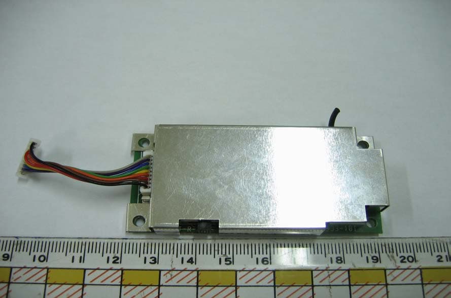
Click to zoom
Application Details
- Equipment Class
- DXX - Part 15 Low Power Communication Device Transmitter
- Date of Grant
- Oct 18, 2005
- Application Purpose
- Original Equipment
- Date of Application
- Oct 18, 2005
- Equipment Note
- FM Module
- Frequency Range
- 88.10000000 - 107.90000000
- Company
- Rosen Entertainment Systems
- Country
- United States
Documents & Files
Document Text
Text extracted from the exhibit documents filed with the FCC. Open a document above to read the original.
Users Manual
Rosen Entertainment Systems LLC 8/30/2005 Rosen FMT. Part # 9100458 Rosen Entertainment Systems Wireless FM Transmitter Part# 9100458 User Guide Rosen Entertainment Systems LLC 8/30/2005 Rosen FMT. Part # 9100458 Table of contents Table of contents......................................................................... 2 General Description ..................................................................... 3 Architectural Overview ................................................................. 3 Block Diagram ............................................................................ 4 Operating Guide .......................................................................... 5 Interface board wiring diagram .................................................. 5 Interface / Pinout Definition.......................................................... 6 Design considerations .................................................................. 6 Appendix 1: Frequency Table ........................................................ 7 Appendix 2: Sample Code ............................................................ 8 Example Code .......................................................................... 8 Appendix 3: Schematic Diagram...................................................10 Appendix 4: Specifications...........................................................11 Rosen Entertainment Systems LLC 8/30/2005 Rosen FMT. Part # 9100458 General Description Rosen’s FMT module, part# 9100458 is a 12-channel FM transmitter designed to transmit audio signals over the FM frequency band to enable users to listen to audio from an independent video system over the existing car audio system via the radio. Architectural Overview The FMT transmitter is designed around the BH1417 from Rohm. Refer to the datasheet for details on this part. The module runs off a 5VDC supply, left and right audio signals should be at 1V RMS to achieve maximum volume. A 74HC161 counter is used to control the channel selection of the FM transmitter. The interface to the counter is accomplished by way of a 3-wire communication bus consisting of CLOCK, CLEAR and GROUND lines. A 5V pulse on the CLOCK line will step to the next channel. A 5V pulse on the CLEAR line will reset back to the default channel. FM transmission can be switched on and off by applying and removing the 5VDC supply to the module itself. Rosen Entertainment Systems LLC 8/30/2005 Rosen FMT. Part # 9100458 Block Diagram The block diagram below shows the main components of the FMT module and how they are interconnected. Stereo TDM Pre-Scalar Pre-Scalar Divide Ratio BH1417F AMP VCO X1 7.60MHz 19KHz Antenna Counter Rosen Entertainment Systems LLC 8/30/2005 Rosen FMT. Part # 9100458 Operating Guide Using the supplied interface board you are able to test the operation of the FMT. To test your FMT setup as follows: Connect the interface board to the FMT using the supplied 9-pin harness. Connect the power wires on the interface board to a voltage supply between 4.8 & 5.2V DC. The red wire should connect to +ve and black should connect to Gnd. Connect a stereo audio source with a maximum 1V RMS signal to Audio_R and Audio_L connectors. Tune your radio receiver to 88.1Mhz. Audio should be heard. To step to the next FM transmission frequency press the channel select switch located on the interface board once. Re-tune your radio to the next frequency and audio should once again be heard at this frequency. Repeat steps 4 & 5 through all the 12 available FM transmission frequencies. For full details see appendix 1 To stop FM transmission, switch off the +5VDC supply. Interface board wiring diagram Rosen Entertainment Systems LLC 8/30/2005 Rosen FMT. Part # 9100458 Interface / Pinout Definition All control and audio is interfaced via a single connector JP1. It is intended to connect to a control board allowing firmware to control the channels selection as well as the power. See the following table for a pin description and definition: FMT JP1 Pin Definitions Pin # Signal Name Function/Description 1 +5V This is the power to the FMT 2 AR_A Right audio input 3 AL_A Left Audio Input 4 GND FMT Ground Reference 5 Load Not used; held low 6 GND FMT Ground Reference 7 SEL2_A Counter clock; sets the output of the counter 8 SEL1_A Counter Clear; resets the counter to 0 9 ANT Not Used; for test purpose only. Design considerations - The module is intended to interface to a control board that will send the required command to select the desired channel. This can be achieved using a simple push button switch interface however the architecture of the interface enables the interface to be controlled by a micro controller. Ideally you should develop an interface that will provide feedback to the user, possibly by way of an OSD, to indicate which channel the transmitter is currently set to. - In order to disable the FM transmission as well as removing the 5VDC supply, the data lines (SEL2_A, SEL1_A, and Load) should be held low. Rosen Entertainment Systems LLC 8/30/2005 Rosen FMT. Part # 9100458 Appendix 1: Frequency Table The frequency table below shows the value of the 74HC161 counter as well as the corresponding FM transmission frequency 2: 88.1 MHz 3: 88.3 MHz 4: 88.5 MHz 5: 88.7 MHz 6: 88.9 MHz 7: < no setting > { 7 is a meaningless value } 8: 106.7 MHz 9: 106.9 MHz 10: 107.1 MHz 11: 107.3 MHz 12: 107.5 MHz 13: 107.7 MHz 14: 107.9 MHz 15: <no setting> { 15 in a meaningless value } Rosen Entertainment Systems LLC 8/30/2005 Rosen FMT. Part # 9100458 Appendix 2: Sample Code The sample code below is used to communicate to the FMT using a PIC micro controller, when using this method in conjunction with outputting information on a video screen a user is able to see visually on screen the status of the FMT. Example Code I/O Name Function SEL1_A: Clear SEL2_B: Clock FMTLOAD: Load (reset) *** INITIALIZATION PROCESS *** // Initialization I/O SEL1_A = 1; SEL2_A = 1; FMTLOAD = 1; // Reset Counte…
Text truncated - open the document above for the full version.
Cover Letter(s)
Rosen Entertainment Systems FCC ID:TI719295300 Request for Modular Approval Transmitter Module Characteristics per FCC public notice DA 00-1407 requirements Item Requirements EUT 1 Have its own RF Shielding The module has its own shielding. Refer to external photos. 2 Have buffered modulation/data inputs (if such inputs are provided) No such design for this FM transmitter module. 3 Have it own power supply regulation This module does not contain an on-board voltage regulator. The transmitter is specified to operate across a voltage range of +5V +/-0.2volt. 4 Meet the antenna requirements of Section 15.203 The antenna is soldered to the module, no consideration of replacement. Refer to internal photos. 5 Be tested in a stand-alone configuration, i.e., the antenna, AC or DC power and data input/output lines must be connected to the module but, the module must not be inside another case during testing The module was tested outside the host device as stand-alone configuration. Refer to setup photos. 6 Be labeled with its own FCC ID number, and if the FCC ID is not visible when the module is installed inside another device, then the outside of the device into which the module is installed must also display a label referring to the enclosed module The module will be labeled with its own FCC ID, and when installed inside another device, the outside of that device will also display a label referring to the enclosed module. 7 The modular transmitter must comply with any specific rule or operating requirements a pplicable to the transmitter and the manufacturer must provide adequate instructions along with the module to explain any such requirements. A copy of these instructions must be included in the application for equipment authorization. For example, there are very strict operational and timing requirements that must be met before a transmitter is authorized for operation under Section 15.231. For instance, data transmission is prohibited, except for operation under Section 15.231(e), in which case there are separate field strength level and timing requirements. Compliance with The module operates under FCC 15.239. these requirements must be assured. 8 Address compliance with the Commission’s RF exposure limits in Sections 1.1310 and 2.1093. In addition, spread spectrum transmitters operating under Section 15.247 are required to address RF exposure compliance in accordance with Section 15.247(4) Complies with RF exposure limits.
Cover Letter(s)
1 Helen Zhao Subject:FW: Rosen Entertainment Systems, FCC ID: TI79295300, Assessment NO.: AN05T5111, Notice#1 Exhibit-C-Test_Rep ort_revised_... From: ss liou Sent: Wednesday, October 19, 2005 2:53 AM To: Helen Zhao Subject: Re: Rosen Entertainment Systems, FCC ID: TI79295300, Assessment NO.: AN05T5111, Notice#1 > Dear Helen, > > #1: The applicant will apply for a limited modular approval. The test data > of installing this device into the host equipment G8 and G10 have been > provided in the revised test report. Please see the attached file. > #2: The test report was revised and the test data at 106.7MHz was added. > Please refer to attached file. > #3: These two channels were blocked and the end user can not tune to them. > The block diagrams were corrected. > #4: The user manual has been revised. > #5: The revised label format including when installing the module in the > host device is provided. > > Best regards, > > S. S. Liou > > > > -----Original Message----- > > From: Compliance Certification Services [mailto:[email protected]] > > Sent: Friday, September 02, 2005 5:30 PM > > To: Helen Zhao > > Subject: Rosen Entertainment Systems, FCC ID: TI79295300, Assessment > > NO.: AN05T5111, Notice#1 > > > > > > Question #1: The modular approval cover letter indicates the module does not > > have buffer, does not have power regulator either, that means it is > > necessary to re-evaluate EMC characteristics when the module is installed > > inside the host device. In that case, Limited modular approval does not > > benefit your client too much, they can use the same FCC ID, but with each > > host, they need to file class II permissive change to repeat the test. 2 > > Please be aware of this. Please provide test data when the module is installed > > inside host equipment G8 and G10. > > > > Question #2: This device operates at 88.1-88.9MHz band and 106.7-107.9MHz > > band, for 88.1-88.9MHz band, it's OK to test at 88.1MHz only, but for 106.7- > > 107.9MHz band, based upon ANSI C63.4:2003, you need to test one near top, > > one near bottom, which will be 106.7MHz and 107.9MHz. Pleas provide test data >> at 106.7MHz. > > Question #3: The block diagram exhibit, as well as BH1417F chipset spec, the > > ocsillator frequency can be tuned to 87.7MHz or 87.9MHz. Please explain how > > the applicant prevent the end user to tune to the frequencies outside the > > allowed band. > > > > Question #4: The user manual does not contain user information as specified > > in FCC15.19. Please add OEM installation instruction to provide installer as > > how to label the final product. > > > > Question #5: Please provide label format when the module is installed inside > > the host device. > > > > Best Regards, > > Helen Zhao > > > > > > The items indicated above must be submitted before processing can continue > > on the above referenced application. Failure to provide the requested > > information within 30 days of the original e-mail date may result in > > application dismissal and forfeiture of the filing fee. Also, please note > > that partial responses increase processing time and should not be > submitted. > > Any questions about the content of this correspondence should be directed > to > > the e-mail address listed below the name of the sender. > > >
External Photos
ETC Report No.:ET94R-08-060 Sheet 1 of 2 Sheets FCC ID.: TI79295300 Rev. No 1.0 CONSTRUCTED PHOTOS of EUT 1. Front View of EUT
ID Label/Location Info
Model : Wireless FM Transmitter Part # 9100458 FCC ID : TI719295300 30mm 15mm Bottom View of Host Equipment Model : XXXXXX Contains FCC ID : TI719295300 30mm 10mm
Internal Photos
ETC Report No.:ET94R-08-060 Sheet 2 of 2 Sheets FCC ID.: TI79295300 Rev. No 1.0 CONSTRUCTED PHOTOS of EUT 2. Component View of PCB 3. Solder View of PCB
Test Report
Rev. No 1.0 FCC Part 15 Subpart C TEST REPORT of E.U.T. : FM Modular FCC ID. : TI79295300 MODEL : Wireless FM Transmitter Working Frequency : 88.1~107.9 MHz for APPLICANT : Rosen Entertainment Systems ADDRESS : 1120 California Ave., Corona, CA 92881 Test Performed by ELECTRONICS TESTING CENTER, TAIWAN NO. 34, LIN 5, DING FU TSUN, LINKOU HSIANG, TAIPEI HSIEN, TAIWAN, R.O.C. http://www.etc.org.tw ; e-mail : [email protected] Tel:(02)26023052 Fax:(02)26010910 Report Number : ET94R-08-060 ETC Report No.:ET94R-08-060 FCC ID.: TI79295300 Rev. No 1.0 TEST REPORT CERTIFICATION Applicant : Rosen Entertainment Systems 1120 California Ave., Corona, CA 92881 Manufacture : Rosen Entertainment Systems 1120 California Ave., Corona, CA 92881 Description of EUT : a) Type of EUT : FM MODULAR b) Trade Name : ROSEN c) Model No : Wireless FM Transmitter d) Working Frequency : 88.1~107.9 MHz e ) Power Supply : 5.0 V DC Regulation Applied : FCC Rules and Regulations Part 15 Subpart C (2005) I HEREBY CERTIFY THAT; The data shown in this report were made in accordance with the procedures given in ANSI C63.4 and the energy emitted by the device was founded to be within the limits applicable. I assume full responsibility for accuracy and completeness of these data. Issued Date : Oct. 14, 2005 Test Engineer : ( Vincent Chang ) Approve & Authorized Signer : Will Yauo, Manager EMC Dept. II of ELECTRONICS TESTING CENTER, TAIWAN ETC Report No.:ET94R-08-060 FCC ID.: TI79295300 Rev. No 1.0 Table of Contents Page 1. GENERAL INFORMATION..................................................................................................1 1.1 Product Description ...........................................................................................................1 1.2 Characteristics of Device: ................................................................................................1 1.3 Test Methodology ..............................................................................................................1 1.4 Test Facility .........................................................................................................................1 2. DEFINITION AND LIMITS....................................................................................................2 2.1 Definition .............................................................................................................................2 2.2 Restricted Bands of Operation ........................................................................................2 2.3 Limitation .............................................................................................................................2 2.4 Labeling Requirement .......................................................................................................3 2.5 User Information ................................................................................................................3 3. SYSTEM TEST CONFIGURATION.....................................................................................4 3.1 Justification ..........................................................................................................................4 3.2 Devices for Tested System ..............................................................................................4 4 RADIATED EMISSION MEASUREMENT..........................................................................5 4.1 Applicable Standard ..........................................................................................................5 4.2 Measurement Procedure ...................................................................................................5 4.3 Measuring Instrument .......................................................................................................7 4.4 Test Data ...............................................................................................................................8 4.4.1 Fundamental and Harmonics.........................................................................................................................8 4.4.2 Other Emissions............................................................................................................................................11 4.5 Field Strength Calculation .............................................................................................11 4.6 Radiated Measurement Photos .....................................................................................12 5 CONDUCTED EMISSION MEASUREMENT...................................................................15 5.1 Standard Applicable...............................................................................................................15 6 ANTENNA REQUIREMENT...............................................................................................16 6.1 Standard Applicable ........................................................................................................16 6.2 Antenna Construction .....................................................................................................16 7 EMISSION BAND MEASUREMENT..................................................................................17 7.1 Standard Applicable ........................................................................................................17 7.2 Measurement Procedure .................................................................................................17 7.3 Measurement Equipment ...............................................................................................17 7.4 Measurement Data ...........................................................................................................17 APPENDIX 1 : PLOTTED DATA FOR EMISSION BAND MEASUREMENT.................18 ETC Report No.:ET94R-08-060 Sheet 1 of 23 Sheets FCC ID.: TI79295300 Rev. No 1.0 1. GENERAL INFORMATION 1.1 Product Description a) Type of…
Text truncated - open the document above for the full version.
Test Setup Photos
ETC Report No.:ET94R-08-060 Sheet 12 of 22 Sheets FCC ID.: TI79295300 Rev. No 1.0 4.6 Radiated Measurement Photos ETC Report No.:ET94R-08-060 Sheet 13 of 22 Sheets FCC ID.: TI79295300 Rev. No 1.0 (Mode: G10) ETC Report No.:ET94R-08-060 Sheet 14 of 22 Sheets FCC ID.: TI79295300 Rev. No 1.0 (Mode: G8)
Contact Information
Applicant
Curtis Kucera(Vice President Engineering / Operations)
Test Firm
Electronics Testing Center, TaiwanWill Yauo
Technical Specifications
| # | Rule Parts | Frequency Range | Power Output |
|---|---|---|---|
| 1 | 15C | 88.1 MHz - 107.9 MHz | - |
Other Applications from Rosen Entertainment Systems
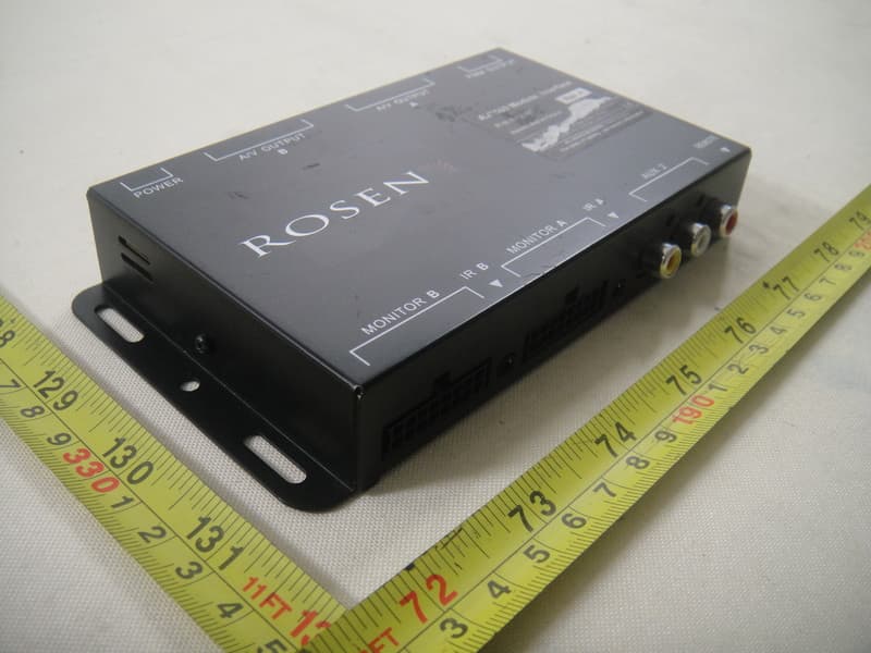
TI7HE0780D
Aug 03, 2011Dual DVD Headrest Replacement System
Equipment Class
DXX - Part 15 Low Power Communication Device Transmitter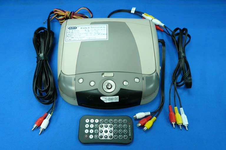
TI7ZE0800D
Mar 02, 2008DVD Player
Equipment Class
DXX - Part 15 Low Power Communication Device Transmitter