TI7HE0780DDual DVD Headrest Replacement System
Rosen Entertainment Systems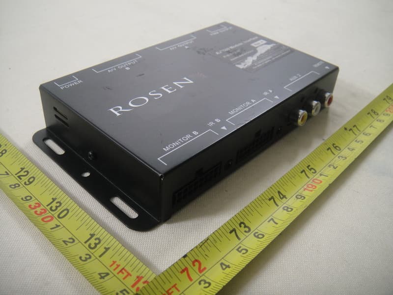
Click to zoom
Application Details
- Equipment Class
- DXX - Part 15 Low Power Communication Device Transmitter
- Date of Grant
- Aug 03, 2011
- Application Purpose
- Original Equipment
- Date of Application
- Aug 01, 2011
- Equipment Note
- Dual DVD Headrest Replacement System
- Frequency Range
- 88.10000000 - 107.90000000
- Company
- Rosen Entertainment Systems
- Country
- United States
Documents & Files
Document Text
Text extracted from the exhibit documents filed with the FCC. Open a document above to read the original.
Users Manual
Rosen Entertainment Systems Copyright 2007 all rights reserved HE0780D Installation Guide AP1024 Rev A Page 1 INSTALLATION GUIDE HE0780D Dual DVD Headrest Replacement System NOTICE OF INTENDED INSTALLATION AND USE E ROSEN ENTERTAINMENT SYSTEMS VIDEO PRODUCTS ARE NOT INTENDED FOR VIEWING BY THE DRIVER, AND ARE TO BE INSTALLED ONLY TO BE VIEWED BY REAR-SEAT OCCUPANTS. IMPROPER INSTALLATION COULD DISTRACT THE DRIVER OR INTERFERE WITH SAFE OPERATION OF THE VEHICLE, WHICH COULD RESULT IN SERIOUS INJURY OR DEATH, AND COULD ALSO VIOLATE STATE LAW. ROSEN ENTERTAINMENT SYSTEMS DISCLAIMS ANY LIABILITY FOR ANY BODILY INJURY OR PROPERTY DAMAGE THAT MAY RESULT FROM ANY IMPROPER OR UNINTENDED INSTALLATION AND/OR USE. BEFORE YOU START THE INSTALLATION, READ THIS GUIDE! Rosen “Headrest DVD” systems are the easiest-to-install DVD entertainment systems available today. However, we strongly recommend reading this guide before starting the installation! For additional technical tips, please visit www.Rosendealercentral.com 1 Make sure you have the tools you will need These common items are needed to complete this installation: · Digital multimeter (DMM) · #2 Phillips screwdriver · Appropriate tool for headrest removal · Allen wrench set · Panel removing tools · Cable routing tool (included) · Security latch tool (included) · Retractable knife · Wire cutters, strippers, and a crimping tool · 1/4” drive sockets are often needed for dashboard and trim disassembly · Check if Torx or Allen-drive bolts are used on any panels you will be removing · You will need a DVD in good condition when testing the system Standard installation parts you will need include wire, wire ties, wire crimp connectors or solder, and electrical insulating tape. Installation of aftermarket automotive electronics also often requires access to special parts. It is a good idea to have a source for these common installation parts. 2 Inspect the vehicle and plan your work k CHECK THE BATTERY Test the battery voltage to make sure it’s fully charged and inspect battery terminals for tightness and any corrosion. This only takes seconds and can save hours of troubleshooting later. DECIDE ON A LOCATION FOR THE INTERFACE UNIT Location of the interface unit varies by vehicle, but is typically secured underneath a driver or passenger seat out of sight and unobstructed by moving parts and passengers. Rosen Entertainment Systems Copyright 2007 all rights reserved HE0780D Installation Guide AP1024 Rev A Page 2 3 Installing the electronics mounting bracket You will need to install the electronics mounting bracket. The following steps will guide you through this process. Step 1: Locate clean, non-abrasive working surface to prepare the headrest units. Step 2: Locate the mounting bracket as shown. Step 3: Install the 4 supplied mounting screws to fully attach the mounting bracket 4 Running the cables through the headrest posts You will need to route the cables through the headrest posts. The following steps will guide you through this process. Step 1: Place the HE0780D electronics system above the headrest bucket as shown in figure 1. Step 2: Position the cables on each side of the headrest bucket and ensure they are smooth without kinks or knots. Step 3: Route the cables through the headrest posts, being careful not to cross the cables. Step 4: Position the HE0780D electronics unit in the headrest bucket while constantly pulling the cable through the headrest posts (see figure 2). This step is critical to prevent damage to the cables or HE0780D unit. IMPORTANT! Do NOT allow the cables to cross over one another or leave excess cable slack in the headrest bucket. This will prevent the unit from closing properly, could permanently damage the unit. Fig. 1 Fig. 2 IF YOU HAVE PURCHASED A PRE-ASSEMBLED HEADREST SYSTEM, SKIP TO SECTION 6 Headrest cushion with electronics mounting bracket installed Rosen Entertainment Systems Copyright 2007 all rights reserved HE0780DInstallation Guide AP1024 Rev A Page 3 5 Mounting the HE0780D electronics into the headrest bucket You will need to mount the HE0780D electronics unit into the headrest bucket. The following steps will guide you through this process. CAUTION! Do NOT press directly on the surface of the LCD. This will cause permanent damage to the LCD which will not be covered by warranty. Always REMOVE ANY SLACK in the cables during assembly. Failure to follow this step may cause damage to the cables. Step 1: Place the lower edge of the HE0780D unit into the headrest bucket first. Be sure that the lower edge of the HE0780D unit does NOT go below the top surface of the headrest bucket (see figure 3). Use caution so the material on the bucket is not damaged. Step 2: Pull any additional slack created in the cables through the headrest posts. Step 3: Align electronics on electronics mounting bracket. Push firmly, the side latch will “click” to lock monitor in place. Remove excess cable slack! Use caution NOT to press on the LCD surface as this can cause permanent damage to the LCD. (see figure 4) IMPORTANT! Do not force electronics into the bracket, the components are designed to easily align when properly installed. BE 100% CERTAIN TO REMOVE ALL SLACK in the cables during assembly of the units. Failure to follow this step may damage the unit, internal cables or prevent the unit from properly closing. If you feel resistance when closing the unit, please confirm that all cable slack has been removed. Fig. 3 Fig. 4 Rosen Entertainment Systems Copyright 2007 all rights reserved HE0780D Installation Guide AP1024 Rev A Page 4 REMOTE POWER A/V OUTPUTA/V OUTPUT FMM OUTPUT MONITOR BMONITOR A IR BIR A AUX 2 Wiring diagram 6 Removing the factory headrests IMPORTANT! Do NOT start this step until you have inspected the seats and factory headrests for any obstructions. You will need to remove the existing factory headrests. The following steps will guide you through this process. Step 1: Determine if a locking device is present on the…
Text truncated - open the document above for the full version.
External Photos
Neutron Engineering Inc. Project No.: 1107C024 Page 24 of 39 1107C024 1107C024 Neutron Engineering Inc. Project No.: 1107C024 Page 24 of 39 1107C024 1107C024
ID Label/Location Info
Neutron Engineering Inc. Project No.: 1107C024 Page 24 of 39 1107C024 1107C024
Internal Photos
Neutron Engineering Inc. Project No.: 1107C024 Page 25 of 39 1107C024 1107C024 Neutron Engineering Inc. Project No.: 1107C024 Page 25 of 39 1107C024 1107C024 Neutron Engineering Inc. Project No.: 1107C024 Page 26 of 39 1107C024 1107C024 Neutron Engineering Inc. Project No.: 1107C024 Page 26 of 39 1107C024 1107C024 Neutron Engineering Inc. Project No.: 1107C024 Page 27 of 39 1107C024 1107C024 Neutron Engineering Inc. Project No.: 1107C024 Page 27 of 39 1107C024 1107C024 Neutron Engineering Inc. Project No.: 1107C024 Page 28 of 39 1107C024 1107C024 Neutron Engineering Inc. Project No.: 1107C024 Page 28 of 39 1107C024 1107C024
Test Report
Report No.: NEI-FCCP-1-1107C024 Page 1 of 36 Neutron Engineering Inc. FCC Radio TEST Report FCC ID: TI7HE0780D This report concerns (check one) : Original Grant Class II Change Issued Date : Jul. 13, 2011 Project No. : 1107C024 Equipment : Dual DVD Headrest Replacement System Model Name : HE0780D Applicant : Rosen Entertainment Systems L.P Address : 1120 California AVE,CORONA,CA92881,USA Manufacturer EVERVICTORY ELECTRONIC COMPANY LIMITED Address Chu Chi Management District, Hu Men Town, Dong-Guan City, Guang-Dong Province, P.R.China Tested by: Neutron Engineering Inc. EMC Laboratory Date of Receipt: Jul. 06, 2011 Date of Test: Jul. 06, 2011 ~ Jul. 12, 2011 Testing Engineer : (Ivan Cao) Technical Manager : (Leo Hung) Authorized Signatory : (Steven Lu) Neutron Engineering Inc. No.3,Jinshagang 1st Road, ShiXia, Dalang Town, Dong Guan, China. TEL : (0769) 8318-3000 FAX : (0769) 8319-6000 Report No.: NEI-FCCP-1-1107C024 Page 2 of 36 Neutron Engineering Inc. Declaration Neutron represents to the client that testing is done in accordance with standard procedures as applicable and that test instruments used has been calibrated with the standards traceable to National Measurement Laboratory (NML) of R.O.C., or National Institute of Standards and Technology (NIST) of U.S.A. Neutron's reports apply only to the specific samples tested under conditions. It is manufacture’s responsibility to ensure that additional production units of this model are manufactured with the identical electrical and mechanical components. Neutron shall have no liability for any declarations, inferences o r generalizations drawn by the client or others from Neutron issued reports. Neutron’s reports must not be used by the client to claim product endorsement by the authorities or any agency of the Government. This report is the confidential property of the client. As a mutual protection to the clients, the public and Neutron-self, extracts from the test report shall not be reproduced except in full with Neutron’s authorized written approval. Neutron’s laboratory quality assurance procedures are in compliance with the ISO Guide 17025 requirements, and accredited by the conformity assessment authorities listed in this test report. Limitation For the use of the authority's logo is limited unless the Test Standard(s)/Scope(s)/Item(s) mentioned in this test report is (are) included in the conformity assessment authorities acceptance respective. Report No.: NEI-FCCP-1-1107C024 Page 3 of 36 Neutron Engineering Inc. Table of Contents Page 1 . CERTIFICATION 5 2 . SUMMARY OF TEST RESULTS 6 2.1 TEST FACILITY 7 2.2 MEASUREMENT UNCERTAINTY 7 3 . GENERAL INFORMATION 8 3.1 GENERAL DESCRIPTION OF EUT 8 3.2 DESCRIPTION OF TEST MODES 10 3.3 BLOCK DIGRAM SHOWING THE CONFIGURATION OF SYSTEM TESTED 11 3.4 DESCRIPTION OF SUPPORT UNITS 12 4 . EMC EMISSION TEST 13 4.1 CONDUCTED EMISSION MEASUREMENT 13 4.1.1 POWER LINE CONDUCTED EMISSION 13 4.1.2 MEASUREMENT INSTRUMENTS LIST 13 4.1.3 TEST PROCEDURE 14 4.1.4 DEVIATION FROM TEST STANDARD 14 4.1.5 TEST SETUP 14 4.1.6 EUT OPERATING CONDITIONS 14 4.1.7 TEST RESULTS 15 4.2 RADIATED EMISSION MEASUREMENT 16 4.2.1 RADIATED EMISSION LIMITS 16 4.2.2 MEASUREMENT INSTRUMENTS LIST 17 4.2.3 TEST PROCEDURE 17 4.2.4 DEVIATION FROM TEST STANDARD 17 4.2.5 TEST SETUP 18 4.2.6 EUT OPERATING CONDITIONS 19 4.2.7 TEST RESULTS (Below 30MHZ) 19 4.2.8 TEST RESULTS (30~1000MHZ) 20 4.3 FIELD STRENGTH OF FUNDAMENTAL AND BAND EDGE EMISSIONS MEASUREMENT 26 4.3.1 LIMITS OF FIELD STRENGTH OF FUNDAMENTAL AND BAND EDGE EMISSIONS MEASUREMENT 26 4.3.2 MEASURING INSTRUMENTS AND SETTING 26 4.3.3 TEST PROCEDURE 26 4.3.4 TEST SETUP LAYOUT 26 4.3.5 TEST DEVIATION 26 5 . BANDWIDTH REQUIREMENT 33 Report No.: NEI-FCCP-1-1107C024 Page 4 of 36 Neutron Engineering Inc. Table of Contents Page 5.1 LIMITS OF EMISSION BAND MEASUREMENT 33 5.1.1 MEASUREMENT INSTRUMENTS LIST 33 5.1.2 TEST PROCEDURE 33 5.1.3 TEST SETUP LAYOUT 33 5.1.4 TEST DEVIATION 33 5.1.5 EUT OPERATION DURING TEST 33 5.1.6 TEST RESULT OF 20dB SPECTRUM BANDWIDTH 34 6 . EUT TEST PHOTO 36 Report No.: NEI-FCCP-1-1107C024 Page 5 of 36 Neutron Engineering Inc. 1. CERTIFICATION E q u i p m e n t : Dual DVD Headrest Replacement System Brand Name : CARSHOW Model Name : HE0780D Applicant : Rosen Entertainment Systems L.P Factory : EVERVICTORY ELECTRONIC COMPANY LIMITED Address : Chu Chi Management District, Hu Men Town, Dong-Guan City, Guang-Dong Province, P.R.China Date of Test : Jul. 06, 2011 ~ Jul. 12, 2011 T e s t I t e m : ENGINEERING SAMPLE Standards : FCC Part15, Subpart C (15.239)/ ANCI C63.4 : 2003 The above equipment has been tested and found compliance with the requirement of the relative standards by Neutron Engineering Inc. EMC Laboratory. The test data, data evaluation, and equipment configuration contained in our test report (Ref No. NEI-FCCP-1-1107C024) were obtained utilizing the test procedures, test instruments, test sites that has been accredited by the Authority of NVLAP and TAF according to the ISO-17025 quality assessment standard and technical standard(s). Report No.: NEI-FCCP-1-1107C024 Page 6 of 36 Neutron Engineering Inc. 2. SUMMARY OF TEST RESULTS Test procedures according to the technical standards: (Antenna to EUT distance is 3 m) FCC Part15, Subpart C / Canada RSS-210:2010 Standard Test Item Limit Frequency Range (MHz) Judgment 15.207 Conducted Emission Class B 0.15 - 30 N/A 15.209 Table(2) Radiated Emission Class B 30-1000 PASS 15.239 A2.8(a) Radiated Emission 250 V/m (48dBV/m) @ 3m 88~108 PASS NOTE: (1)” N/A” denotes test is not applicable in this Test Report Report No.: NEI-FCCP-1-1107C024 Page 7 of 36 Neutron Engineering Inc. 2.1 TEST FACILITY The test facilities used to collect the test data in this report is DG-C03/DG-CB03 at the location of No.3,Jinshagang 1st Road, ShiXia, Dalang Town, Dong Guan, China.523792 Neutron's test firm number for FCC 319330 2.2 MEASUREMENT UNCERTAINTY Where relevant, the following measurement uncertainty levels have been estima…
Text truncated - open the document above for the full version.
Test Setup Photos
Report No.: NEI-FCCP-1-1107C024 Page 36 of 36 Neutron Engineering Inc. 6. EUT TEST PHOTO Radiated Measurement Photos Report No.: NEI-FCCP-1-1107C024 Page 36 of 36 Neutron Engineering Inc. 6. EUT TEST PHOTO Radiated Measurement Photos
Contact Information
Applicant
Curtis Kucera(Vice President Engineering / Operations)
Technical Contact
Test Firm
BTL Inc.Daisy Dai
Technical Specifications
| # | Rule Parts | Frequency Range | Power Output |
|---|---|---|---|
| 1 | 15C | 88.1 MHz - 107.9 MHz | - |
Other Applications from Rosen Entertainment Systems
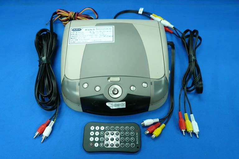
TI7ZE0800D
Mar 02, 2008DVD Player
Equipment Class
DXX - Part 15 Low Power Communication Device Transmitter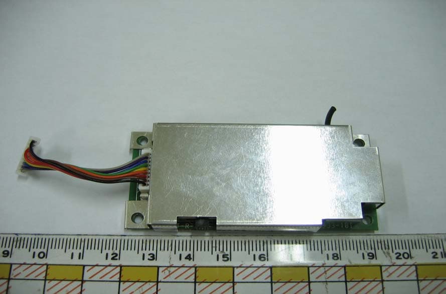
TI79295300
Oct 18, 2005FM Module
Equipment Class
DXX - Part 15 Low Power Communication Device Transmitter