TIUIW261CColor Weather Forecast Station
Nexus Industrial Design Ltd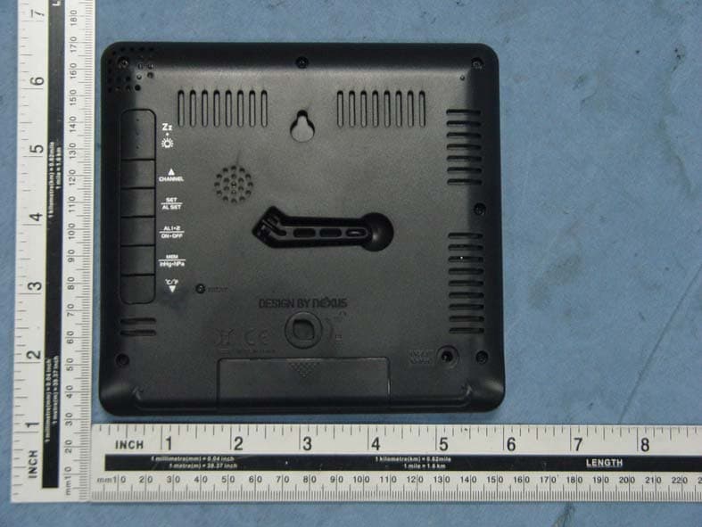
Click to zoom
Application Details
- Equipment Class
- CYY - Communications Receiver used w/Pt 15 Transmitter
- Date of Grant
- Aug 24, 2015
- Application Purpose
- Original Equipment
- Date of Application
- Aug 24, 2015
- Equipment Note
- Color Weather Forecast Station
- Frequency Range
- 433.92000000 - 433.92000000
- Company
- Nexus Industrial Design Ltd
- Country
- Hong Kong
Documents & Files
Document Text
Text extracted from the exhibit documents filed with the FCC. Open a document above to read the original.
Users Manual
Reset RF Transmission LED Reset Outdoor wireless transmitter FCC ID: TIUIW261C INPUT : DC5V BATTERY: DC4.5V 3xAAA Stand BATTERY + / - DIRECTION 1. INSERT THE STAND HORIZONTALLY 2. THEN ROTATE THE STAND CLOCKWISE BY 90° TO SECURE IT Stand / LED RESET HOLDER INSERT 2 x AAA BATTERIES CHANNEL 1 CHANNEL 2 CHANNEL 3 WIRELESS OUTDOOR TRANSMITTER FCC ID: TIUTW003 Model No. TW003 1.5V / AAA x 2 FCC ID: TIUTW003 Model No. TW003 1.5V / AAA x 2 INSTRUCTION MANUAL OF IW261C-N COLOR WEATHER FORECAST STATION V1.1 - June. 18, 2015 INSTRUCTION MANUAL OF IW261C-N COLOR WEATHER FORECAST STATION V1.1 - June. 18, 2015 RF 433.92MHz RF 433.92MHz P. 2 FEATURE LIST 4.7” / 120mm (diagonal) display with 1.1” time digits Alarm 1 and Alarm 2 Programmable Snooze 5-60 minutes Dimmer for nighttime viewing Color forecast : Sunny, Partly Cloudy, Cloudy, Rainy, Stormy 12-hour forecast based on changing air pressure Tendency indicator of weather forecast Indoor-outdoor temperature and humidity (RH%) Max-Min records of temperature and humidity Month-Date Calendar interchangeable with Air pressure readout (inHg) Degree C/F readout 12/24 hour time format 433Mhz wireless outdoor transmitter (one transmitter is included) Up to 50-meter transmission of outdoor temperature and humidity Auto scrolling of outdoor temperatures and humidity of up to three transmitters Low battery indicator of outdoor transmitter Can expand to use with two additional outdoor transmitters (purchase separately) Main unit powered by external AC/DC adaptor Batteries : 3 “AAA” alkaline for backup of the main weather station (not included) : 2 “AAA” alkaline for outdoor transmitter (not included) QUICK SETUP Step 1: Power up your weather station Insert the AC/DC adaptor to any 120V AC household outlet. Then insert the DC jack to the back case of your unit. Take out the stand at the back case and insert it horizontally to the back case, then rotate it by 90 degree to secure it to the back case. Step 2: install batteries to your outdoor transmitter Keep your weather station and wireless outdoor transmitter next to each other. Slide open the battery cover at the back of your wireless outdoor transmitter, then insert 2 x AAA alkaline batteries to the battery compartment. Make sure the Channel selector is at 1 position. Replace the battery cover. Remark : Make sure (Channel 1) is displayed under the outdoor temperature and humidity. You could press / CHANNEL to select Channel 1. Your weather station will receive data signal from the outdoor transmitter in few seconds. Then place your outdoor transmitter in a dry and shaded area. P. 3 Installing backup batteries to your weather station Your weather station requires 3 “AAA” alkaline batteries to provide backup power to it in the event of a temporary power interruption. 1. Place your unit face down on a flat surface. 2. Slide and remove the battery cover at the bottom of your unit. 3. Insert 3 “AAA” alkaline batteries into the battery compartment by observing the “+” and “-“ polarity as indicated. 4. Replace the battery cover. If the AC main power is interrupted, the backlight will go off. The backup batteries will keep the time and all settings of your unit. Press once to turn on the backlight for 5 seconds. Remarks: Keep in mind that your outdoor transmitter has a 180-ft open air transmission with no obstructions. Actual transmission range will vary depending on what is in the path of the signal. Each obstruction (roof, walls, floors, ceilings, thick trees, etc.) will effectively cut signal range in half. Insert the holder to the bottom of the outdoor transmitter for desktop or insert it to the back of the transmitter for wall mount purpose. TO SET YOUR UNIT MANUALLY The setting of your unit comes into the sequence of 12/24 hour, hours, minutes, year, month, date, month- date/date-month display and snooze duration. 1. Press and hold for 2 seconds, time digits change to “12Hr“ and flash. Press or to select “24 Hr” time format if need. When 12Hr time format is selected, PM indicator will be displayed. 2. Then press once again, “12” the hour digits flash. Press or button to set the hours. Press and hold / will accelerate your setting faster. 3. Then press once again, “00”” the minute digits flash. Press or button to set the minutes. Press and hold / will accelerate your setting faster. 4. Then press once again, “Yr” and “2013” digits flash. Press or button to set the year. P. 4 5. Then press once again, month digits flash. Press or button to set the month. 6. Then press once again, date digits flash. Press or button to set the date. 7. Then press once again, “m”, “d”, month-date digits flash. Press or to select month-date “m” “d” or date-month “d” “m” calendar display. 8. Then press once again, “SN” and “05”. Press or button to set the snooze duration from 5 minutes to 60 minutes. 9. Press to return to normal mode, or it will return to normal mode in around 10 seconds if no further press of any other buttons. TO SET ALARM TIME 1. Press once, time digits change to alarm time digits “6:00” and “A1”. Then press and hold for 2 seconds, the alarm hour digits flash. Press or to set the hours of your desired alarm time. 2. Then press once again, the alarm minute digits flash. Press or button to set the minutes of your desired alarm time. 3. Press once, time digits change to alarm time digits “6:00” and “A2” is displayed. Then repeat the above in Alarm 1 setting. P. 5 3. Your weather station will return to normal mode, or it will return to normal mode in around 10 seconds if no further press of any other buttons. TO TURN ON OR OFF YOUR DAILY ALARM Simply press to turn on or off the Alarm 1, Alarm 2, or Alarm 1 & 2. When Alarm 1 is turned on, the appears. When Alarm 2 is turned on, the appears. TO USE SNOOZE ALARM When time reaches your set alarm time, your weather station will give a beep sound to wake you up. The corresponding or will f…
Text truncated - open the document above for the full version.
Cover Letter(s)
SCS-F18: Project and Product Certification Representative Authorization Letter Page 1 of 2 Rev 5.0 775 Montague Expressway Milpitas, CA 95035 Tel: 408-526-1188 Fax: 408-526-1088 Email: [email protected] Project and Product Certification Representative Authorization Letter Revision History Reason for Amendment (current / obsolete) From To Approved Date Initial Release (obsolete) 1.0 1.0 Nov-14-2006 Revised wording (obsolete) 1.0 2.0 Sept–25-2007 Updated company template (obsolete) 2.0 3.0 Jan-31-2012 Updated letter information (obsolete) 3.0 4.0 May-23-2014 Added FCC ID field (current) 4.0 5.0 Sept 16 2014 SCS-F18: Project and Product Certification Representative Authorization Letter Page 2 of 2 Rev 5.0 Nexus Industrial Design Ltd 2015-08-07 To: SIEMIC, INC. 775 Montague Expressway, Milpitas, CA 95035 USA Dear Sir/Madam, Re: Product Certification Representative Authorization Letter We, Nexus Industrial Design L td hereby authorize SIEMIC, Inc. to act as a Certification Body for certifying for the following project(s): Product Description: Color Weather Forecast Station Model name: IW261C FCC ID: TIUIW261C Sincerely, Client’s signature Client’s name / title: Charles Wong / Project Executive Contact information / address :15/F., Tower 2, Tern Centre, 251 Queen’s Road Central, Hong Kong
Cover Letter(s)
SCS-F19: Confidentiality Request Letter Page 1 of 2 Rev 4.0 775 Montague Expressway Milpitas, CA 95035 Tel: 408-526-1188 Fax: 408-526-1088 Email: [email protected] Confidentiality Request Letter Revision History Reason for Amendment (current / obsolete) From To Approved Date Initial Release (obsolete) 1.0 1.0 Nov-14-2006 Adding CFR 2.459 (obsolete) 1.0 2.0 August – 11 - 2008 Updated company template & Added text box (obsolete) 2.0 3.0 Jan-31-2012 Added IC confidentiality letter form (current) 3.0 4.0 March-26-2015 SCS-F19: Confidentiality Request Letter Page 2 of 2 Rev 4.0 Nexus Industrial Design Ltd 2015-08-07 To: Federal Communications Commission Authorization and Evaluation Division 7435 Oakland Mills Road Columbia, MD Subject: Permanent Confidentiality Request for FCC ID: TIUIW261C We hereby request confidential treatment of information accompanying this application as outlined below: - Block Diagram - Schematics - Operational Description The above materials contain trade secrets and proprietary information not customarily released to the public. The public disclosure of these materials may be harmful to the applicant and provide unjustified benefits to its competitors. The applicant understands that pursuant to Section 0.457 & 0.459 of the Rules, disclosure of this application and all accompanying documentation will not be made before the date of the Grant for this application. Sincerely, Client’s signature : Client’s name / title:Charles Wong / Project Executive Contact information / address :15/F., Tower 2, Tern Centre, 251 Queen’s Road Central, Hong Kong
ID Label/Location Info
Back view ( Black casing Engraving (-0.3mm) Size : 7.4 x 4.3 mm Engraving (-0.3mm) Size : 31.3 x 3 mm Engraving (-0.3mm) Size : 21.2 x 8.9 mm Engraving (-0.3mm) Size : 5.6 x 1.6 mm Engraving (-0.3mm) Size : 7.5 x 12 mm Engraving Size : 53 x 4.6 mm FCC ID: TIUIW261C MODEL NO. : IW261C Back view ( Black casing FCC ID: TIUIW261C MODEL NO. : IW261C Buttons Silkscreen Color : White Color Size : 9.6 x 61 mm FCC ID: TIUIW261C MODEL NO. : IW261C FCC Silkscreen Color : White Color Size : 42.7 x 25.9 mm
Test Report
Report No.: ATE20151492 Page 1 of 23 FCC ID: TIUIW261C ACCURATE TECHNOLOGY CO., LTD APPLICATION FOR VERIFICATION On Behalf of Nexus Industrial Design Ltd Color Weather Forecast Station Model No.: IW261C FCC ID: TIUIW261C Prepared for : Nexus Industrial Design Ltd Address : 15/F., Tower 2, Tern Centre, 251 Queen’s Road Central, Hong Kong Prepared by : Accurate Technology Co., Ltd. Address : F1, Bldg. A&D, Changyuan New Material Port, Keyuan Rd., Science & Industry Park, Nanshan District, Shenzhen 518057, P.R. China Tel: +86-755-26503290 Fax: +86-755-26503396 Report No. : ATE20151492 Date of Test : Jul 08-14,2015 Date of Report : Jul 15,2015 Report No.: ATE20151492 Page 2 of 23 FCC ID: TIUIW261C ACCURATE TECHNOLOGY CO., LTD TABLE OF CONTENTS Description Page Test Report Declaration 1. TEST RESULTS SUMMARY......................................................................................................... 4 2. GENERAL INFORMATION............................................................................................................ 5 2.1. Product of Device (EUT).......................................................................................................................5 2.2. Accessory and Auxiliary Equipment....................................................................................................5 2.3. Description of Test Facility...................................................................................................................6 2.4. Measurement Uncertainty.....................................................................................................................6 3. MEASURING DEVICE AND TEST EQUIPMENT .............................................................. 7 4. POWER LINE CONDUCTED MEASUREMENT......................................................................... 7 4.1. Block Diagram of Test Setup....................................................................................................................9 4.2. The Emission Limit ..................................................................................................................................9 4.3. Configuration of EUT on Measurement............................................................................................10 4.4. Operating Condition of EUT...............................................................................................................10 4.5. Test Procedure.....................................................................................................................................10 4.6. Power Line Conducted Emission Measurement Results...............................................................11 5. RADIATED EMISSION MEASUREMENT................................................................................. 17 5.1. Block Diagram of Test Setup..................................................................................................................17 5.2. The Emission Limit For Section 15.109 (a) ...........................................................................................18 5.3. EUT Configuration on Measurement................................................................................................18 5.4. Operating Condition of EUT...............................................................................................................18 5.5. Test Procedure.....................................................................................................................................18 5.6. Radiated Emission Noise Measurement Result..............................................................................19 Report No.: ATE20151492 Page 3 of 23 FCC ID: TIUIW261C ACCURATE TECHNOLOGY CO., LTD Test Report Declaration Applicant : Nexus Industrial Design Ltd Manufacturer : Nexus Industrial Design Ltd EUT Description : Color Weather Forecast Station (A) MODEL NO.: IW261C (B) SERIAL NO.: N/A (C) POWER SUPPLY: AC 100-240V Measurement Procedure Used: FCC Rules and Regulations Part 15 Subpart B Class B & ANSI C63.4: 2014 The device described above is tested by Accurate Technology Co., Ltd. to determine the maximum emission levels emanating from the device. The maximum emission levels are compared to the FCC Part 15 Subpart B Class B limits both radiated and conducted emissions. The measurement results are contained in this test report and Accurate Technology Co., Ltd. is assumed full responsibility for the accuracy and completeness of these measurements. Also, this report shows that the Equipment Under Test (EUT) is to be technically compliant with the FCC requirements. This report applies to above tested sample only. This report shall not be reproduced in part without written approval of Accurate Technology Co., Ltd. Date of Test : Jul 08-14,2015 Date of Report : Jul 15,2015 Prepared by : (Mark Chen, Engineer) Approved & Authorized Signer : (Sean Liu, Manager) Report No.: ATE20151492 Page 4 of 23 FCC ID: TIUIW261C ACCURATE TECHNOLOGY CO., LTD 1. TEST RESULTS SUMMARY Test Items Test Standard Test Results Power Line Conducted Emission FCC Part 15.107 Pass Radiated Emission FCC Part 15.109 Pass Report No.: ATE20151492 Page 5 of 23 FCC ID: TIUIW261C ACCURATE TECHNOLOGY CO., LTD 2. GENERAL INFORMATION 2.1.Product of Device (EUT) EUT : Color Weather Forecast Station Model Number : IW261C Power Supply : AC 100-240V Adapter : Model number: SW0500300-A04 Input: 100-240V; 50/60Hz 200mA Output: DC 5V/300mA Line: Non-shielded, Non-detachable, 1.5m Modulation: : ASK Operation Frequency : 433.92MHz RX Applicant : Nexus Industrial Design Limited Address : 15/F., Tower 2, Tern Centre, 251 Queen’s Road Central, Hong Kong. Manufacturer : Nexus Industrial Design Limited Address : 15/F., Tower 2, Tern Centre, 251 Queen’s Road Central, Hong Kong Date of sample received : Jul 08,2015 Date of Test : Jul 08-14,2015 2.2.Accessory and Auxiliary Equipment NA Report No.: ATE20151492 Page 6 of 23 FCC ID: TIUIW261…
Text truncated - open the document above for the full version.
Contact Information
Applicant
Charles Wong
Test Firm
Accurate Technology Co., Ltd.Sean Liu
Technical Specifications
| # | Rule Parts | Frequency Range | Power Output |
|---|---|---|---|
| 1 | 15B | 433.92 MHz - 433.92 MHz | - |
Other Applications from Nexus Industrial Design Ltd

TIU-ST-100
Oct 29, 2013Bluetooth Speaker with Cooking Thermo
Equipment Class
DSS - Part 15 Spread Spectrum Transmitter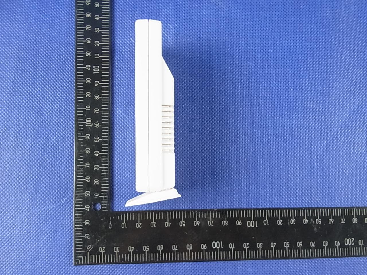
TIUTW003
Apr 10, 2013LCD Weather Station
Equipment Class
DSC - Part 15 Security/Remote Control Transmitter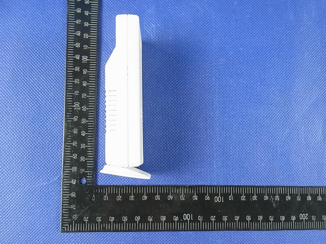
TIUTW004
Apr 10, 2013LCD Weather Station
Equipment Class
DSC - Part 15 Security/Remote Control Transmitter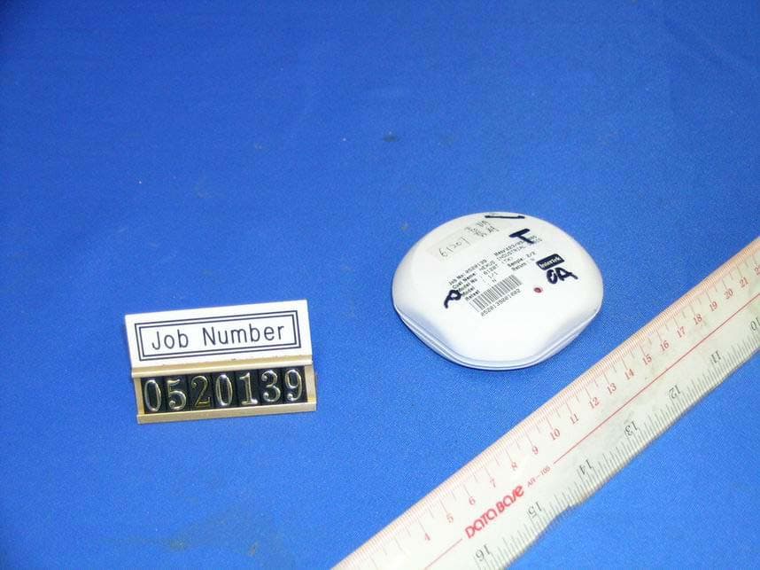
TIU6120T
Dec 03, 2005Wireless Outdoor Sensor (Transmitter)
Equipment Class
DSC - Part 15 Security/Remote Control Transmitter
TIUK0240T
Nov 10, 2005LCD Cooking Thermometer
Equipment Class
DSC - Part 15 Security/Remote Control Transmitter