TIUTW004LCD Weather Station
Nexus Industrial Design Ltd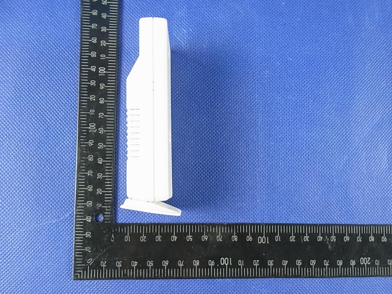
Click to zoom
Application Details
- Equipment Class
- DSC - Part 15 Security/Remote Control Transmitter
- Date of Grant
- Apr 10, 2013
- Application Purpose
- Original Equipment
- Date of Application
- Apr 10, 2013
- Equipment Note
- LCD Weather Station
- Frequency Range
- 433.92000000 - 433.92000000
- Company
- Nexus Industrial Design Ltd
- Country
- Hong Kong
Documents & Files
Document Text
Text extracted from the exhibit documents filed with the FCC. Open a document above to read the original.
Users Manual
Englis h GREAT BRITAIN For consumer contact, please visit www.clasohlson.co.uk and click on customer service. Sensor for weather station Model Please read the entire instruction manual before use and save it for future reference. We reserve the right for any errors in text or images and for making any necessary technical changes to this document. If you should have any questions concerning technical problems please contact our Customer Services. Safety • Never subject the outdoor sensor to tempera- tures outside the specified range, extensive sunlight, or rain. • Never mix old and new batteries or alkaline and rechargeable batteries. • Remove the batteries if the product is not to be used for a long time. Old batteries can begin to leak and damage the product. • Remember to always insert the batteries according to the markings in the battery com- partment. The wrong polarity (+/-) can dam- age the weather station. • Damage that has occurred by careless han- dling is not covered by the guarantee. • The product must not be modified in any way. Synchronising the sensor with the weather station Before starting: The units should be placed near to one another to ensure a successful synchronisation (when the outdoor temperatu re appears on the display the synchronisation has been successful). Once synchronised, the sensor and weather station can be placed in their intended locations within functional range. 1. Pr ess +/CHANNEL on the weather station one or more times to select channel 2 (CH2). 2. Hold in +/CHANNEL until starts to flash, the weather station will now start to search for a sensor on channel 2. 3. Remove the battery cover of the sensor, set the channel selector to position 2 and then insert two batteries according to the polarity markings. Replace the battery cover. 4. The temperature readings fr om sensor 2 will now be shown at the same time as the CH2 symbol. If no readings ar e shown on channel 2, you must reset and repeat the synchronisation procedure: Pr ess RESET on the fr ont of sensor once. 5. Repeat the above procedure for sensor 3 if required. 1 2 3 4 1. LED indicator 2. Reset 3. Battery cover 4. Channel selector TW004
External Photos
APPENDIX-PHOTOGRAPHS OF EUT CONSTRUCTIONAL DETAILS Photo 1 Photo 2 Photo 3 Photo 4 Photo 5 Photo 6
ID Label/Location Info
UNIVERSAL RESOURCES TW004 FCC 30mm 16mm
Internal Photos
Photo 7 Photo 8 Photo 9 Photo 10 Photo 11
Test Report
FCC RADIO TEST REPORT FCC ID:TIUTW004 Product: LCD Weather Station Trade Name: N/A Model Name: TW004 Serial Model: N/A Report No.: NTEK-2013NT0327061F Prepared for Nexus Industrial Design Ltd. 15/F., Tower 2, Tern Centre, 251 Queen's Road Central, Central, Hong Kong Prepared by Shenzhen NTEK Testing Technology Co., Ltd. 1/F, Building E, Fenda Science Park, Sanwei Community,Xixiang Street Bao’an District, Shenzhen P.R. China Tel.: +86-0755-61156588 Fax.: +86-0755-61156599 Website:www.ntek.org.cn Page 2 of 27 Report No.: NTEK-2013NT0327061F ` TEST RESULT CERTIFICATION Applicant’s name ................. : Nexus Industrial Design Ltd. Address ................................. : 15/F., Tower 2, Tern Centre, 251 Queen's Road Central, Central, Hong Kong Product description Product name............................ : LCD Weather Station Model and/or type reference : TW004 Serial Model: N/A Rating(s) ................................ : DC 3V Standards ............................. : FCC Part15.231 Test procedure ............................... : ANSI C63.4-2003 This device described above has been tested by NTEK, and the test results show that the equipment under test (EUT) is in compliance with the FCC requirements. And it is applicable only to the tested sample identified in the report. This report shall not be reproduced except in full, without the written approval of NTEK, this document may be altered or revised by NTEK, personal only, and shall be noted in the revision of the document. Date of Test ........................................... : Date (s) of performance of tests ............. : 15 Mar. 2013 ~24 Mar. 2013 Date of Issue .......................................... : 25 Mar. 2013 Test Result.............................................. : Pass Testing Engineer : (Apple Huang) Technical Manager : (Tom Zhang) Authorized Signatory : (Bovey Yang) Page 3 of 27 Report No.: NTEK-2013NT0327061F ` Table of Contents Page 1 . SUMMARY OF TEST RESULTS 4 1.1 TEST FACILITY 5 1.2 MEASUREMENT UNCERTAINTY 5 2 . GENERAL INFORMATION 6 2.1 GENERAL DESCRIPTION OF EUT 6 2.2 DESCRIPTION OF TEST MODES 7 2.3 BLOCK DIGRAM SHOWING THE CONFIGURATION OF SYSTEM TESTED 8 2.4 DESCRIPTION OF SUPPORT UNITS(CONDUCTED MODE) 9 2.5 EQUIPMENTS LIST FOR ALL TEST ITEMS 10 3 . ANTENNA REQUIREMENT 11 3.1 STANDARD REQUIREMENT 11 3.2 EUT ANTENNA 11 3.3 CONDUCTED EMISSION MEASUREMENT 12 3.3.1 POWER LINE CONDUCTED EMISSION LIMITS 12 3.3.2 TEST PROCEDURE 13 3.3.3 DEVIATION FROM TEST STANDARD 13 3.3.4 TEST SETUP 13 3.2.5 TEST RESULT 14 3.4 RADIATED EMISSION MEASUREMENT 15 3.4.1 RADIATED EMISSION LIMITS 15 3.4.2 TEST PROCEDURE 16 3.4.3 DEVIATION FROM TEST STANDARD 16 3.4.4 TEST SETUP 17 3.4.5 TEST RESULTS (BLOW 30MHZ) 19 3.4.6 TEST RESULTS (BETWEEN 30 – 1000 MHZ) 20 4 . BANDWIDTH TEST 22 4.1 TEST PROCEDURE 22 4.2 DEVIATION FROM STANDARD 22 4.3 TEST SETUP 22 4.4 TEST RESULTS 23 5 . TRANSMITTER TIMEOUT 24 5.1 REQUIREMENTS 错误!未定义书签。 6 . EUT TEST PHOTO 27 APPENDIX-PHOTOGRAPHS OF EUT CONSTRUCTIONAL DETAILS Page 4 of 27 Report No.: NTEK-2013NT0327061F ` 1. SUMMARY OF TEST RESULTS Test procedures according to the technical standards: FCC Part15, Subpart C (15.231) Standard Section Test Item Judgment Remark 15.207 Conducted Emission N/A Note(1) 15.203 Antenna Requirement Pass 15.231 Radiated Spurious Emission Pass 15.231 Occupied Bandwidth Pass 15.231 Deactivation Time Pass NOTE: (1) ” N/A” denotes test is not applicable in this Test Report. Page 5 of 27 Report No.: NTEK-2013NT0327061F ` 1.1 TEST FACILITY NTEK Testing Technology Co., Ltd Add. : 1/F, Building E, Fenda Science Park, Sanwei Community, Xixiang Street, Bao’an District, Shenzhen P.R. China. FCC Registration No.:238937; IC Registration No.:9270A-1 CNAS Registration No.:L5516 1.2 MEASUREMENT UNCERTAINTY The reported uncertainty of measurement y ± U,where expended uncertainty U is based on a standard uncertainty multiplied by a coverage factor of k=2,providing a level of confidence of approximately 95 %。 No. Item Uncertainty 1 Conducted Emission Test ±1.38dB 2 RF power,conducted ±0.16dB 3 Spurious emissions,conducted ±0.21dB 4 All emissions,radiated(<1G) ±4.68dB 5 All emissions,radiated(>1G) ±4.89dB 6 Temperature ±0.5°C 7 Humidity ±2% Page 6 of 27 Report No.: NTEK-2013NT0327061F ` 2. GENERAL INFORMATION 2.1 GENERAL DESCRIPTION OF EUT Equipment LCD Weather Station Trade Name N/A Model Name TW004 Serial Model N/A Model Difference N/A Product Description The EUT is a LCD Weather Station Product Type Low Power Communication Device Transmitter Operation Frequency: 433.92MHz Modulation Type: ASK Number Of Channel 1CH. Antenna Designation: Wire Spiral antenna Antenna Gain(Peak) 0.16 dBi Output Power: 71.84 dBuV/m (AV Max.) More details of EUT technical specification, please refer to the User's Manual. Channel List N/A Adapter N/A Battery 1.5V*2cell “AAA” alkaline battery Note: 1. For a more detailed features description, please refer to the manufacturer’s specifications or the User's Manual. 2. Table for Filed Antenna Ant . Brand Model Name Antenna Type Connector Gain (dBi) NOTE 1 N/A N/A Spiral Antenna N/A 0.16 Antenna Page 7 of 27 Report No.: NTEK-2013NT0327061F ` 2.2 DESCRIPTION OF TEST MODES To investigate the maximum EMI emission characteristics generates from EUT, the test system was pre-scanning tested base on the consideration of following EUT operation mode or test configuration mode which possible have effect on EMI emission level. Each of these EUT operation mode(s) or test configuration mode(s) mentioned above was evaluated respectively. Pretest Mode Description Mode 1 TX For Conducted Emission Final Test Mode Description Mode 1 N/A For Radiated Emission Final Test Mode Description Mode 1 TX Note: (1) The EUT use new battery. Page 8 of 27 Report No.: NTEK-2013NT0327061F ` 2.3 BLOCK DIGRAM SHOWING THE CONFIGURATION OF SYSTEM TESTED Radiated Spurious Emission Test E-1 EUT Page 9 of 27 Report No.: NTEK-2013NT0327061F ` 2.4 DESCRIPTION OF SUPPORT UNITS(CONDUCTED MODE) The EUT has bee…
Text truncated - open the document above for the full version.
Test Setup Photos
Page 27 of 27 Report No.: NTEK-2013NT0327061F ` 6. EUT TEST PHOTO Radiated Measurement Photos(worst case position)
Contact Information
Applicant
Charles Wong
Test Firm
Shenzhen NTEK Testing Technology Co., Ltd.Jason Chen
Technical Specifications
| # | Rule Parts | Frequency Range | Power Output |
|---|---|---|---|
| 1 | 15.231 | 433.92 MHz - 433.92 MHz | - |
Other Applications from Nexus Industrial Design Ltd
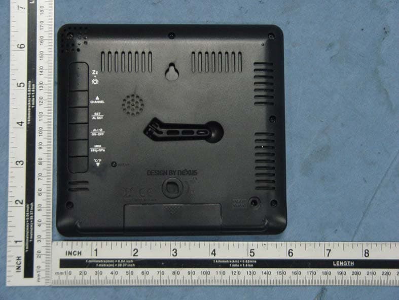
TIUIW261C
Aug 24, 2015Color Weather Forecast Station
Equipment Class
CYY - Communications Receiver used w/Pt 15 Transmitter
TIU-ST-100
Oct 29, 2013Bluetooth Speaker with Cooking Thermo
Equipment Class
DSS - Part 15 Spread Spectrum Transmitter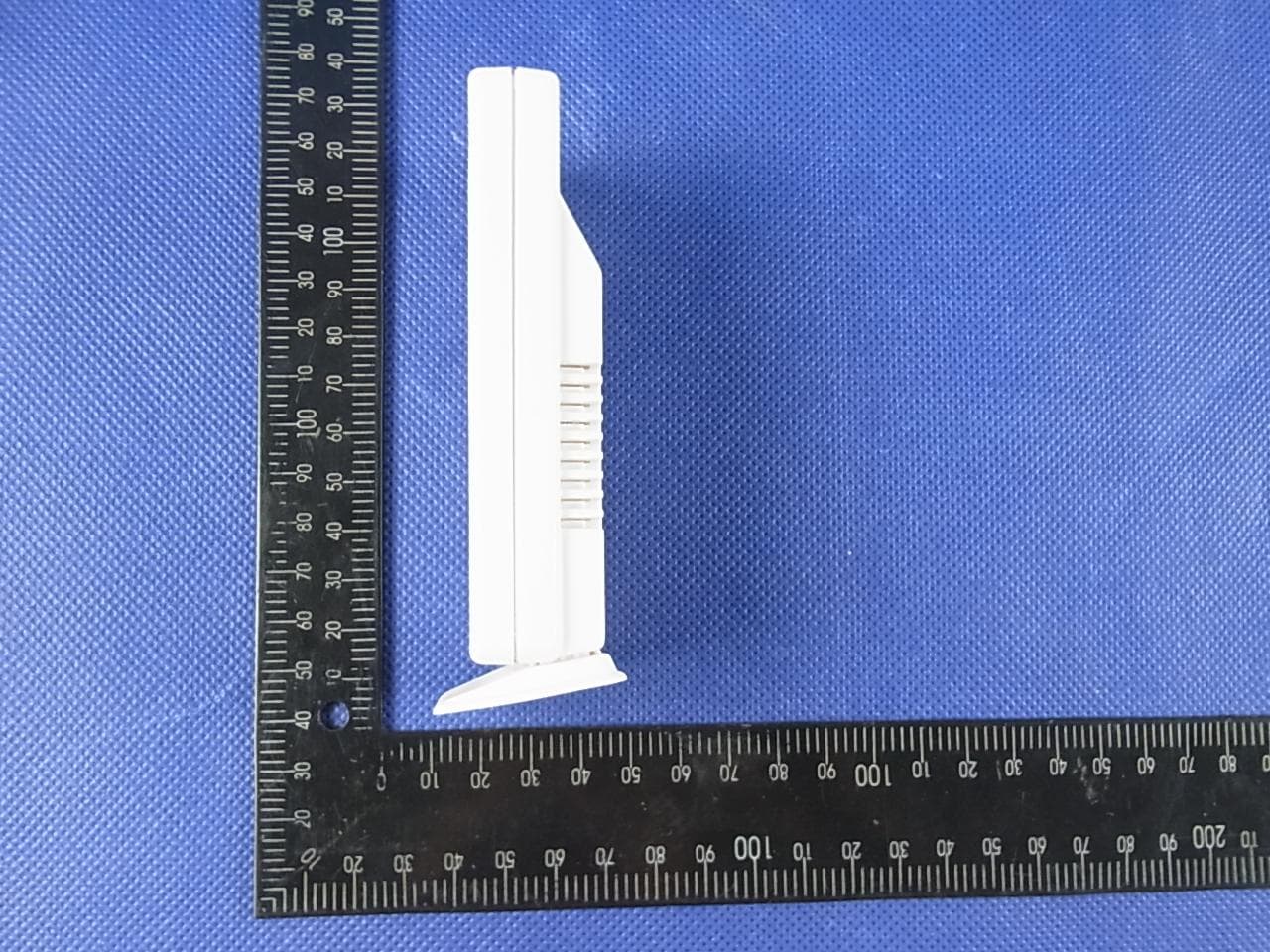
TIUTW003
Apr 10, 2013LCD Weather Station
Equipment Class
DSC - Part 15 Security/Remote Control Transmitter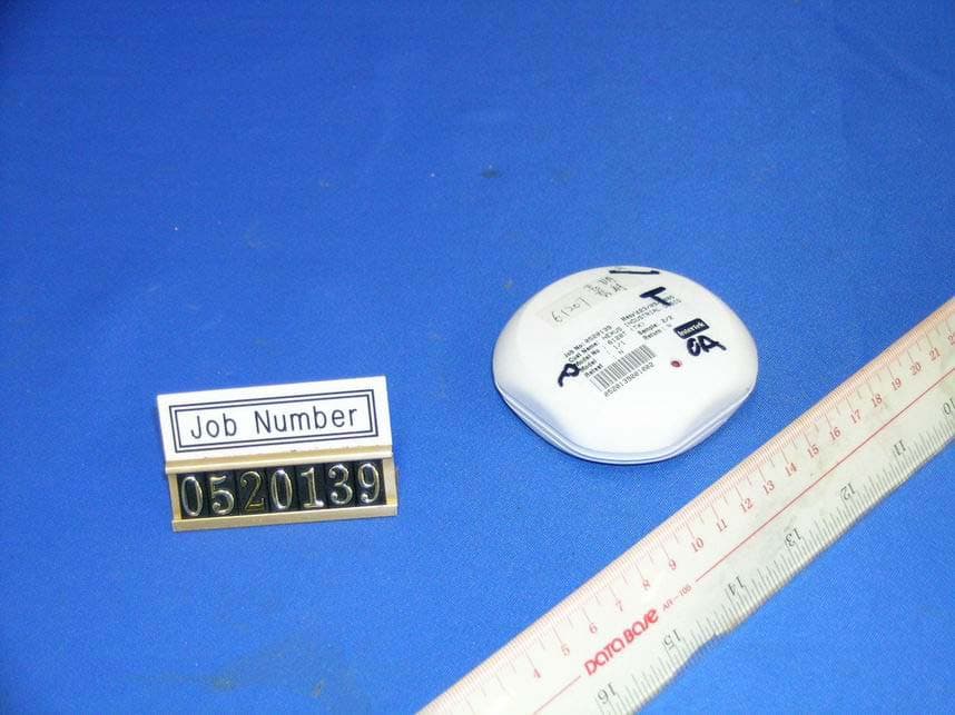
TIU6120T
Dec 03, 2005Wireless Outdoor Sensor (Transmitter)
Equipment Class
DSC - Part 15 Security/Remote Control Transmitter
TIUK0240T
Nov 10, 2005LCD Cooking Thermometer
Equipment Class
DSC - Part 15 Security/Remote Control Transmitter