TJ7BTK-801BLUETOOTH HANDS-FREE CAR KIT MIRROR
Shenzhen SHI KISB Electronic Co., Ltd.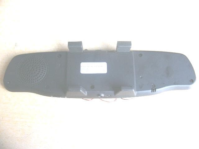
Click to zoom
Application Details
- Equipment Class
- DXX - Part 15 Low Power Communication Device Transmitter
- Date of Grant
- Dec 30, 2007
- Application Purpose
- Original Equipment
- Date of Application
- Dec 27, 2007
- Equipment Note
- BLUETOOTH HANDS-FREE CAR KIT MIRROR
- Frequency Range
- 2402.00000000 - 2480.00000000
- Country
- China
Documents & Files
Document Text
Text extracted from the exhibit documents filed with the FCC. Open a document above to read the original.
Users Manual
ENGLISH CONTENTS BTK-801 ILLUSTRATION.................. 1 INSTALLATION.................. 2 POWER ON/OFF.................. 3 PAIR.................. 3 CONNECTING..................3 ASWERING AND ENDING A CALL......4 VOICE DIALLING............ 4 LAST CALL REDIALING............ 4 REJECTING A CALL...... 5 REC.................. 5 PLAYBACK...... 5 VOLUME CONTROL...... 6 CHARGING............6 USING THE EARPHONE...... 6 TROUBLESHOOTING............ 7 CARE AND MAINTENANCE ..................9 SPECIFICATIONS............10 MEMO............11 Page A THANK YOU TO PURCHASE THIS PRODUCT Thank you to purchase the BTK-801 Bluetooth Handsfree Car Kit.We hope you will be satified with it. For the sake of making use of the Bluetooth Car Kit’s multi-function most adequately, please read the user manual care fully before use. Drive Safely It is dangerous to use mobile phone when driving a car.It will increase the possibility of an accident. Please reduce conversation time by mobile as possibly as you can when you are driving. It is good for you not to do any record or read. You’ d better observe the surroundings before using the mobile first. When it’s necessary (if the car or something wrong with the car), you should leave the road and stop the car before the car before dialing or receiving a call. Page B BTK-801 ILLUSTRATION 1. 2. 3. Page 1 BLUETOOTH HANDSFREE CAR KIT MIRROR USER MANUAL INSTALLATION Easy installation, step as following: First, place the upper holder of BTK-801 to the top side of the rear-view mirror in you car. Push BTK—801 closely to the mirror and place the lower holder of BTK-801 to fit completely. Tips: Place BTK-801 in the center of the rear-view mirror in you car. If not, the sound could be diminished. Page 2 POWER ON/OFF At first, change power switch to “on” place below “ON/OFF”. Press function key (TALK/RADIAL/WAITING) and hold for 2 seconds, Until "ON" display on mirror and come with come with indicator LED flashing, the device will be on. Under standby mode, press function key and hold for 4 seconds, "OFF " will be displayed on mirror and come with indicator LED off .the device will be off. PAIRING "Pair "means to setup connection between device and mobile with blutooth, and the mobile phone will store device's ID. Under standby state, press "TALK" key for 5 second, the device will connect to mobile phone after paired. “PAIR” will be displayed on mirror. Password:0000 CONNECTING Mobile phone can connect to the device automatically after paired successfully when turn on the device, or press “FUNCTION” key, it will automatically connect with the last mobile phone which has paired successfully, and “CONNECT” will be displayed on the mirror. Page 3 Answering or ending a call Incoming a call, press “FUNCTION” key to answer a call, and “CALLING”will be displayed on the mirror., press “FUNCTION” key again to ending a call, and “HANGUP”will be displayed on the mirror. Voice dialing Ensure mobile phone has connected to device, press “FUNCTION” key quickly once, bring out ore-recoded voice tag, and “VOICE”will displayed on the mirror. Note: This function depends on mobile phone. Some mobile phone don’t support voice dialing. Please refer to mobile phone user manual. Last call redialing Ensure mobile phone has connected to device, press ”FUNCTION” key quickly twice, if your mobile phone support last call redialing, it will redial the last number, and “Redial” will be displayed on the mirror. Page 4 Rejecting a call Incoming a call, press “FUNCTION” key for 2 second, ending the call and “HANG UP” will be displayed on the mirror. REC During conversation, press “REC” key, indicate LED flashing, “START RECORD” display on the mirror; use last for 2 minutes or press “STOP RECORD”key again, the indicate LED will off, and “STOP RECORD”will display on the mirror. Without conversation model, quickly press the “ REC ” key will delete the record. Playback Without conversation model, quickly press “Play” key, indicate LED will flashing, and “PLAY” will display on the mirror; Press “REC” or “Play” key again will stop playback, and “STOP” will display on the mirror. Page 5 VOLUME CONTROL In conversation model, Rotate the knob deasil to increase volume, anticlockwise decrease volume. Note: Don't adjust volume to maximum when use earphone. CHARGING During standby or conversation,handsfree will generate a “Do Do” sound and Blue LED is flashing. It indicates low battery. Please charge the device use car charger ( DC Jack outlet and USB outlet are both available) . Charging indicator light will on during charging, and will off when charged. Approximately charging time is about 2 hours. USING THE EARPHONE (Option) You can have a private conversation with the earphone. For this function, please connect earphone with BTK-801, the device will be in earphone use mode automatically. NOTE: The Character and typeface will be keep to what indicate on the mirror Page 6 TROUBLESHOOTING BTK-801 does not turn on. Check Whether the battery of BTK-801 is full charged. Charge the battery Check Whether the Power cable is inserted properly Insert cable again Check Whether the Power switch is turned on Turn on Power switch Can not have a conversation through BTK-801 Check Whether the handset supports handsfree profile In order to have a conversation through BTK-801,a Bluetooth handset that support handsfree profile is required Check Whether the battery of BTK-801 is low Charge the battery Page 7 Can not pair BKT-801 with the Bluetooth device. Check Whether the power of BTK-801 is turned on Turn on the power switch or insert the power cable No sound from the speaker Check Whether the volume status is at lower level Deasil the knob to decrease volume Page 8 CARE AND MAINTENANCE Your device is a products of superior design and craftsmanship and should be treated with care. The suggestions below will help you protect your warranty coverage. 1. Do not drop the unit from high please. 2. Do not modify, repair nor take apart at discretion. 3…
Text truncated - open the document above for the full version.
External Photos
EUT top view EUT bottom view
ID Label/Location Info
The Label must not be a stick-on paper label. The Label on these products must be permanently affixed to the product and readily visible at the time of purchase and must last the expected lifetime of the equipment not be readily detachable. Proposed Label Location on EUT EUT Bottom View/Proposed FCC ID Label Location FCC ID: TJ7BTK-801
Internal Photos
EUT inside whole view Main board component side Main board solder side
Operational Description
Bluetooth headset operates in the 2.4GHz range, exactly between the 2.402GHz and the 2.480GHz.The maximum of covering range is 10m. BlueCore4 Bluetooth IC is the center of the whole block, integrated the RF circuit and baseband-controlling circuit, and supplied ample interfaces. In the block a embedded voltage regulator supplies 1.8V positive voltage for Balum etc..
Schematics
1234 A B C D E F G H 4 321 H G F E D C B A GND 1 PIO/8 2 PIO/9 3 PIO/0 4 PIO/1 5 PIO/2 6 PIO/3 7 PIO/10 8 PIO/11 9 PIO/7 10 PIO/5 11 PIO/4 12 PIO/6 13 GND 14 SPI/MISO 15 SPI/CLK 16 SPI/CSB 17 SPI/MOSI 18 RESET 19 RESET/B 20 PCM/OUT 21 PCM/CLK 22 PCM/SYNC 23 PCM/IN 24 1.8V 25 GND 26 3.3V 27 USP/DP 28 USP/DN 29 UART/TX 30 UART/RX 31 UART/CTS 32 UART/RTS 33 GND 34 AIO/3 35 AIO/1 36 AIO0 37 MIC/R- 38 MIC/R+ 39 MIC/L- 40 MIC/L+ 41 GND 42 SPK/R+ 43 SPK/R- 44 SPK/L+ 45 SPK/L- 46 GND 47 GND 48 RF 49 GND 50 U5 BC3-MODULE MOSI CSB CLK MISO 1.8V C1 0.1uF BAT1 3.7V C9 10uF BAT L3 10uH C32 10uF 3.7V ON 1.8V C22 0.1uF C28 0.01uF C29 0.01uF 3V C35 4.7uF ON BYP 4 GND 2 CE 3 VIN 1 VOUT 5 U3 RT9193-3V IN 1 AGND 2 /SHDN 3 OUT 4 LX 5 U2 XC9216-1.8V 3.7V C30 0.01uF 2.8V/MIC C34 4.7uF PIO/11 BYP 4 GND 2 CE 3 VIN 1 VOUT 5 U4 RT9193-2.8V 3.7V L2 15nH C17 15P R34 2.2K C15 47nF C14 47nF R27 150K R29 100K R31 1M C19 NC 2.8V/MIC R25 150K 1% R23 220K 1% C11 1uF 3.7V AIO/0 3.7V C23 0.1uF MIC/L-MIC/L+ L4 NC C38 NC ANT1 ANT-PCB-S C20 15P TP4 MOSI TP3 CSB TP8 CLK TP9 MISO TP6 1.8V TP10 GND 1.8V C3 0.1uF C2 0.1uF 1.8V 3V R43 10K R46 10K R42 10K R44 10K PIO/5PIO/2PIO/3 R47 47K R48 47K R49 47K R51 47K C24 0.1uF R5 47K PIO/9 SW2 VOL+ SW3 VOL- SW4 PLAY SW6 UKEY R32 1M R52 10K D1 1N5819 ON C4 0.1uF 5V AIO/0 PIO/4PIO/5PIO/10PIO/3PIO/1PIO/9 TP5 RF TP11 GND TP7 3V LEDS 1 TS 2 VSS 3 BAT 4 VCC 8 DRIVE 5 CS1 6 CS2/LEDT 7 U1 VM7205 R2 47K R1 47K R15 0R PIO/11PIO/2 3V PIO/0 Q3 2N3904 R9 47K R57 330R LED3 LED-B 3.7V PIO/0 PIO/4 AIO/1 AIO/3 R56 330R R8 47K PIO/1 SP1 8R/2W SD 1 VP 2 INP 3 INM 4 OUTP 5 VP 6 GND 7 OUTM 8 U6 NCP2820-BGA R4 47K R6 47K PIO/10 3.7V C33 10uF C25 0.1uF SPK/R+ SPK/R- SPK/L+ SPK/L- C5 1uF C6 1uF C21 NC Q2 2N3904 C36 1uF MIC1 MIC-S Q1 SPC2811 R17 1K R19 1.5R R20 1.5R 5V R16 330R R18 1.5R LED1 LED-R BAT PIO/6PIO/7 R3 47K R21 NC 5V RESET/5V RESET/5V PIO/8 R38 47K R24 150K 1% R22 220K 1% C10 1uF 5V AIO/3 R45 10K PIO/6 R50 47K SW5 REC R58 330R R10 47K PIO/7 Q4 2N3904 LED2 LED-R 3.7V CHANG-LED CHANG-LED SW1 POWER BAT R7 47K LIN C7 1uF SPK/L+ SPK/L- TXRX TP1 TX TP2 RX 1 2 3 4 5 J2 PJ-004A-SMD USB+USB- D2 SM5819 GND 0 GND 1 NC 2 D+ 3 D- 4 5V 5 GND 0 J1 USB-5P R61 22R R60 22R R62 2.2K 5V 3V R40 NC R39 NC USB+ USB- R59 1.5K D3 1N5819
Schematics
ABCD DCBA MR 1 VCC 2 GND 3 PFI 4 PFO 5 WDT 6 RESET 7 WDO 8 U14 SP706P P1.5 1 P1.6 2 P1.7 3 RST 4 RXD/P3.0 5 P4.3/INT2/ 6 TXD/P3.1 7 INT0/P3.2 8 INT1/P3.3 9 T0/P3.4 10 T1/P3.5 11 P3.6 12 P3.7 13 XTAL2 14 XTAL1 15 VSS 16 P4.0 17 P2.0 18 P2.1 19 P2.2 20 P2.3 21 P2.4 22 P2.5 23 P2.6 24 P2.7 25 PSEN 26 ALE 27 P4.1 28 EA 29 P0.7 30 P0.6 31 P0.5 32 P0.4 33 P0.3 34 P0.2 35 P0.1 36 P0.0 37 VDD 38 P4.2 39 P1.0/T2 40 P1.1/T2EX 41 P1.2 42 P1.3 43 P1.4 44 U10 STC89LE58RD 1B 1 2B 2 3B 3 4B 4 5B 5 6B 6 7B 7 COM 9 7C 10 6C 11 5C 12 4C 13 3C 14 2C 15 1C 16 GND 8 U11 ULN2003 C44 20P C4320P R64 4.7K R5410KR5310K R1347K R1147K R63 4.7KR65 4.7KR66 4.7KR67 4.7KR68 4.7KR69 4.7K R1247K R5510K MOSI/CMISO/CSCLK/CSS/CTXRXWDT Y1 11.0592M C-COM5 C-COM6 C-COM7 C-COM8 C-COM9 C-COM10C-COM11C-COM12 3.3V 3.3V CO-SEG5CO-SEG6CO-SEG7CO-SEG8 CO-SEG1 CO-SEG2 CO-SEG3 CO-SEG4 3.3V C-COM1 C-COM2 C-COM3 C-COM4 INTRAC 3.3V WDT RESET RESET R72 100R R71 100R R73 100R R74 100R R78100R R77100R R70 4.7K CO-SEG1CO-SEG2CO-SEG3CO-SEG4CO-SEG5CO-SEG6CO-SEG7CO-SEG8 C-SEG1C-SEG2C-SEG3C-SEG4C-SEG5C-SEG6C-SEG7C-SEG8 C-COM1C-COM2C-COM3C-COM4C-COM5C-COM6 1B 1 2B 2 3B 3 4B 4 5B 5 6B 6 7B 7 COM 9 7C 10 6C 11 5C 12 4C 13 3C 14 2C 15 1C 16 GND 8 U12 ULN2003 C-COM7C-COM8C-COM9C-COM10C-COM11C-COM12 D-COM1D-COM2D-COM3D-COM4D-COM5D-COM6 D-COM7D-COM8D-COM9D-COM10D-COM11D-COM12 3.3V 3.3V A 1 B 2 C 3 D 4 E 5 COM4 6 DP 7 COM3 8 COM2 9 G 10 F 11 COM1 12 U7 LED-4X D-SEG1D-SEG2D-SEG3D-SEG4D-SEG5 D-SEG6D-SEG7D-SEG8 A 1 B 2 C 3 D 4 E 5 COM4 6 DP 7 COM3 8 COM2 9 G 10 F 11 COM1 12 U9 LED-4X D-SEG1D-SEG2D-SEG3D-SEG4D-SEG5 D-SEG6D-SEG7D-SEG8 A 1 B 2 C 3 D 4 E 5 COM4 6 DP 7 COM3 8 COM2 9 G 10 F 11 COM1 12 U8 LED-4X D-SEG1D-SEG2D-SEG3D-SEG4D-SEG5 D-SEG6D-SEG7D-SEG8D-COM1D-COM2D-COM3 D-COM4 D-COM5D-COM6D-COM7 D-COM8 D-COM9D-COM10D-COM11 D-COM12 R76100R R75100R 3.3V 3.3V 3.3V 3.3V3.3V 3.3V 3.3V 3.3V C-SEG1 C-SEG2 C-SEG3 C-SEG4 C-SEG5 C-SEG6 C-SEG7 C-SEG8 D-SEG1 D-SEG2 D-SEG3 D-SEG4 D-SEG5 D-SEG6 D-SEG7 D-SEG8 C46 47uF 3.3V C8 0.1uF SS 1 MOSI 2 MISO 3 VSS 4 NC 5 NC 6 NC 7 NC 8 NC 9 NC 10 VSS 11 VSS 12 AUD OUT 13 AMCAP 14 NC 15 ANA IN- 16 ANA IN+ 17 VCC 18 NC 19 NC 20 NC 21 NC 22 VSS 23 RAC 24 INT 25 XCLK 26 VCC 27 SCLK 28 U13 ISD4002-120S C26 0.1uF C27 0.1uF C39 1uF C401uF C42 0.47uF R8010K R36 2.2K MISO/CMOSI/CSCLK/CSS/C R35 2.2K R7910K C41 0.47uF SPK/R-SPK/R+ RACINT C45 47uF 3.3V LIN C31 0.01uF PIO/8 BYP 4 GND 2 CE 3 VIN 1 VOUT 5 U15 RT9193-3.3V 3.7V C37 1uF R37 10K C47 4.7uF 3.3V Q5 2N3906 Q6 2N3906 Q7 2N3906 Q8 2N3906 Q9 2N3906 Q10 2N3906 Q11 2N3906 Q12 2N3906 R81 10KR82 10KR83 10KR84 10KR85 10KR86 10K 3.3V R87 10KR88 10KR89 10KR90 10KR91 10KR92 10K 3.3V TP12 3.3V TP13GND
Test Report
The test report consists 23 pages in total. It may be duplicated completely for legal use with the allowance of the applicant. It shall not be reproduced except in full, without the written approval of Ke Mei Ou Laboratory Corporation. The test result in the report only applied to the tested sample. FCC TEST REPORT Under FCC 15 Subpart C, Paragraph 15.249: 2004 Prepared For : Kiss Communications Technology Co., Ltd. B213,Natai Electronics Center, No.8,Xi Di Er Road, Guangzhou, China December 5, 2007 FCC ID: TJ7BTK-801 EUT: Bluetooth Handsfree Car Kit Mirror Model: BTK-801 Report Type: Original Report Test Engineer: Jacky Huang Test Date: November 30, 2007 Review By: Apollo Liu / Manager Ke Mei Ou Laboratory Co., Ltd. 7A, Jiaxiangge, Jiahuixincheng, No.3027, Shennan Rd., Futian, Shenzhen, Guangdong, P.R.China. Zip Code: 518033 Tel: + 86 755 83642690 Fax: + 86 755 83297077 www.kmolab.com FEDERAL COMMUNICATIONS COMMISSION Registration Number: 125782 INDUSTRY CANADA Registration Number: IC4986 Kiss Communications Technology Co., Ltd FCC ID: TJ7BTK-801 KMO FCC ID Report Report #: KSZ2007112801J Page 2 of 23 TABLE OF CONTENTS 1. General Information....................................................................................................................................................3 1. 1 Notes......................................................................................................................................................................3 1. 2 Testing Laboratory..................................................................................................................................................3 1. 3 Details of Applicant................................................................................................................................................3 1. 4 Application Details..................................................................................................................................................3 1. 5 Test Item.................................................................................................................................................................3 1. 6 Test Standards.........................................................................................................................................................3 2. Technical Test...............................................................................................................................................................4 2. 1 Summary of Test Results.........................................................................................................................................4 3. EUT Modifications.......................................................................................................................................................4 4. Conducted Power Line Test.........................................................................................................................................5 4. 1 Test Equipment.......................................................................................................................................................5 4. 2 Test Procedure........................................................................................................................................................5 4. 3 Test Setup...............................................................................................................................................................5 4. 4 Configuration of the EUT........................................................................................................................................6 4. 5 EUT Operating Condition........................................................................................................................................7 4. 6 Conducted Power Line Emission Limits..................................................................................................................7 4. 7 Conducted Power Line Test Result...........................................................................................................................7 5. Radiated Emission Test................................................................................................................................................8 5. 1 Test Equipment.......................................................................................................................................................8 5. 2 Test Procedure........................................................................................................................................................8 5. 3 Radiated Test Setup.................................................................................................................................................8 5. 4 Configuration of the EUT........................................................................................................................................9 5. 5 EUT Operating Condition........................................................................................................................................9 5. 6 Radiated Emission Limit.........................................................................................................................................9 5. 7 Radiated Emission Test Result...............................................................................................................................10 6. Band Edge..................................................................................................................................................................12 6. 1 Test Equipment.....................................................................................................................................................12 6. 2 Test Procedure.......................................................................…
Text truncated - open the document above for the full version.
Test Setup Photos
Radiated emission test view
Contact Information
Applicant
KK Lee(General Manager)
Test Firm
SinTek Laboratory Co., Ltd.Eric Lin
Technical Specifications
| # | Rule Parts | Frequency Range | Power Output |
|---|---|---|---|
| 1 | 15C | 2.40 GHz - 2.48 GHz | - |
Other Applications from Shenzhen SHI KISB Electronic Co., Ltd.
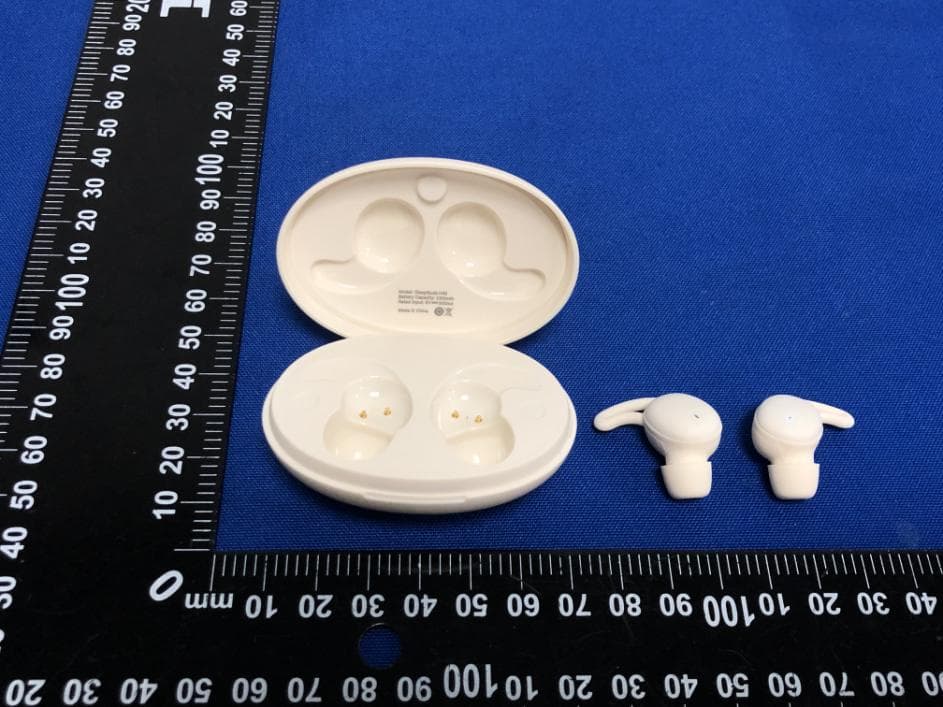
TJ7-H40
Jul 26, 2023TRUE WIRELESS EARBUDS
Equipment Class
DSS - Part 15 Spread Spectrum Transmitter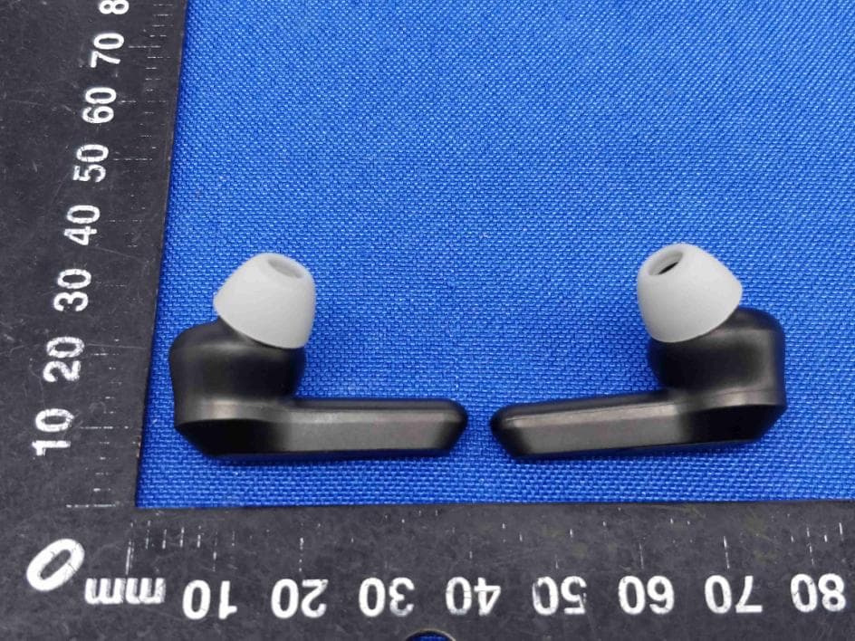
TJ7-H21B
Aug 02, 2021TRUE WIRELESS EARBUDS
Equipment Class
DSS - Part 15 Spread Spectrum Transmitter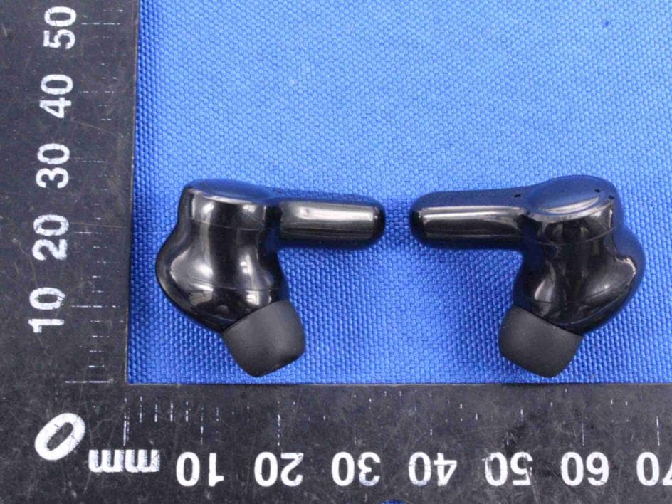
TJ7-H29
Jun 01, 2021TRUE WIRELESS EARBUDS
Equipment Class
DSS - Part 15 Spread Spectrum Transmitter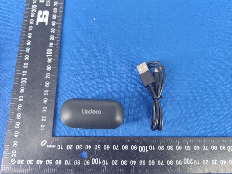
TJ7-H26
May 18, 2021TRUE WIRELESS EARBUDS
Equipment Class
DSS - Part 15 Spread Spectrum Transmitter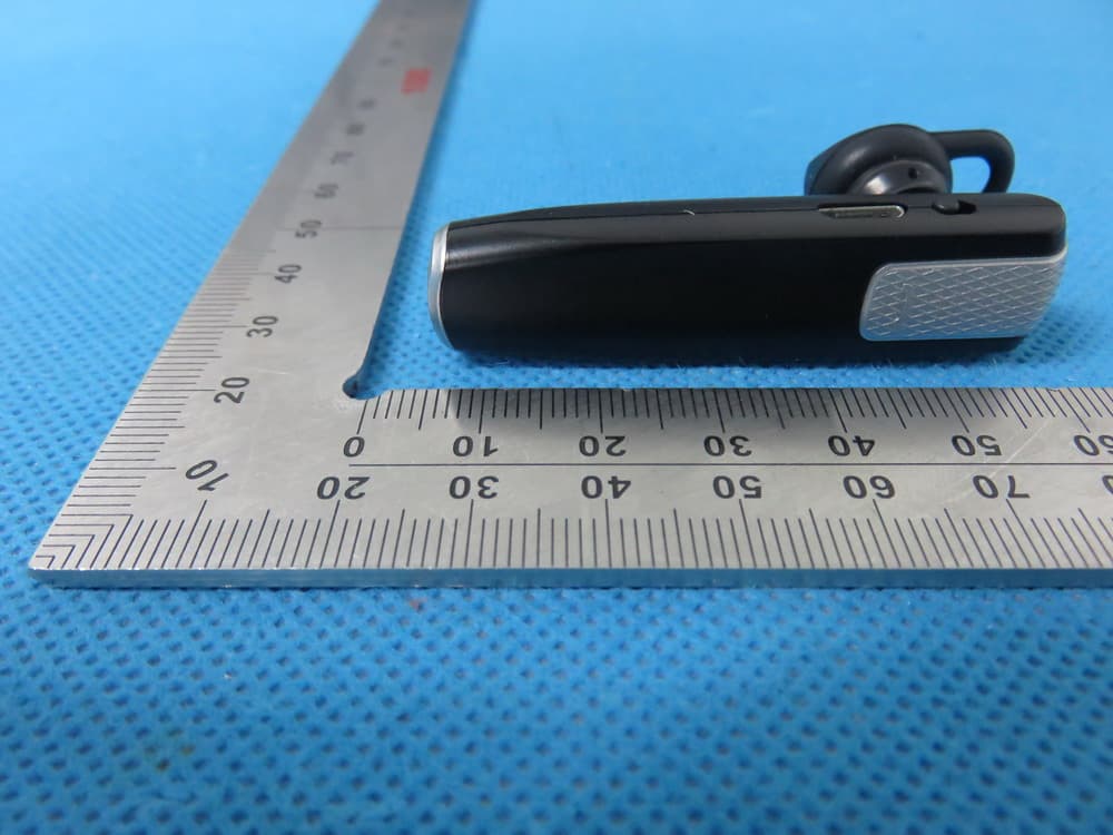
TJ7VALOREBTK-C5
Jul 14, 2015Bluetooth Headset
Equipment Class
DXX - Part 15 Low Power Communication Device Transmitter