TK5-910EWTXMotion Tracker
Thales Visionix, Inc.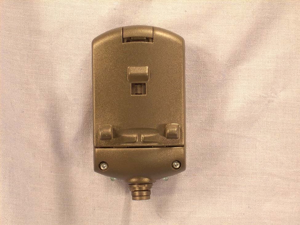
Click to zoom
Application Details
- Equipment Class
- DTS - Digital Transmission System
- Date of Grant
- Sep 03, 2007
- Application Purpose
- Original Equipment
- Date of Application
- Sep 03, 2007
- Equipment Note
- Motion Tracker
- Frequency Range
- 2405.00000000 - 2480.00000000
- Company
- Thales Visionix, Inc.
- Country
- United States
Documents & Files
Document Text
Text extracted from the exhibit documents filed with the FCC. Open a document above to read the original.
Users Manual
Doc. No. 072-00092-000B Rev. 2.1 User Guide IS-900 SimTracker & VETracker with MicroTrax TM Devices 2007 InterSense, Inc. 36 Crosby Drive, Suite 150 Bedford, MA 01730 Phone +1 781 541 6330 • Fax +1 781 541 6329 www.intersense.com IS-900 User Guide Page 2 of 159 User Guide for the IS-900 SimTracker & VETracker Firmware 4.20 and higher DLL Version 3.75 and higher Contacting InterSense Please contact us if you need assistance. InterSense, Inc. 36 Crosby Drive Suite 150 Bedford, Massachusetts 01730 USA Telephone: +1 781 541 6330 email: [email protected] Fax: +1 781 541 6329 Internet: www.intersense.com Technical Support: +1 781 541 7624 email: [email protected] Sales: +1 781 541 7618 email: [email protected] Patents The label below identifies the protection granted by the Government of the United States to InterSense for its products: Trademarks InterSense™, InertiaCube™, InertiaCube2™ SoniDisc™, SoniStrip™, SoniFrame™, SoniPod™ IS-900™, VETracker™, SimTracker™, ISDEMO™, GEOS™, PULSAR™, CONSTELLATION™, MicroTrax™ are trademarks of InterSense Inc. All other trademarks are the property of their respective owners. Copyright 2007 InterSense, Inc. U.S. Patents 5645077, 5807284, 6162191, 6176837, 6314055, 6361507, 6409687, 6474159,6681629, 6757068, 6786877, 6922632, 700469 and Patents Pending IS-900 User Guide Page 3 of 159 Warnings and Precautionary Statements Any changes or modifications to the IS-900 SimTracker/VETracker, MicroTrax Tracking Devices and other components of the IS-900 System not expressly approved by InterSense will void the warranty and any regulatory compliance issued for the system. This could also void the user’s authority to operate the equipment. Wand and Head tracker microphones are susceptible to ESD and may require power cycling to recover from communication failure. Do not drop or otherwise shock the tracking devices for they can be permanently damaged. Do not bend, twist, pull strongly or tamper in any way with any part of the cabling. Take care to avoid electric shocks. Do not plug-in or unplug the power cable with wet hands. Please see Appendix C for Health and Safety warnings and guidelines Wireless Devices This device contains a Lithium Ion battery that should only be used with the following warnings and precautions. • Avoid short circuits • Do not dispose of the battery in fire • Do not heat the batteries above 60°C • Do not solder directly to the batteries • Do not charge above 4.2V • Do not charge below 0°C or above 45°C • Do not discharge below 2.7V • Do not discharge below 20°C or above 60°C • Do not insert the batteries in reverse polarity IS-900 User Guide Page 4 of 159 Warning: Fire, Explosion, and Severe Burn Hazard IS-900 User Guide Page 5 of 159 Equipment Design: • To avoid damage to the battery pack, make sure that the battery pack is positioned away from heat sources in the equipment. • If the battery pack is designed into other equipment, use caution to strictly avoid designing airtight battery compartments. When using the battery Misusing the battery may cause the battery to get hot, explode, or ignite and cause serious injury. Be sure to follow the safety rules listed below: v Do not place the battery in fire or heat the battery. v Do not pierce the battery with nails, strike the battery with a hammer, step on the battery, or otherwise subject it to strong impacts or shocks. v Do not expose the battery to water or salt water or allow the battery to get wet. Do not disassemble or modify the battery. The battery contains safety and protection devices, which, if damaged, may cause the battery to generate heat, explode or ignite. Do not place the battery on or near fires, stoves, or other high-temperature locations. Do not place the battery in direct sunshine, or store the battery inside cars in hot weather. Doing so may cause the battery to generate heat, explode, or ignite. Using the battery in this manner may also result in the loss of performance and shortened life expectancy. When the battery will no longer hold a charge, contact InterSense for servicing options. Do not exchange with any other battery. Immediately discontinue use of the battery if, while using, charging or storing the battery the battery emits an unusual smell, feels hot, changes color, changes shape or appears abnormal in any other way. Contact InterSense if any of these problems have been observed. Do not place the batteries in microwave ovens, high-pressure containers, or on induction cookware. In the event that the battery leaks and fluid gets into one’s eye, do not rub the eye. Rinse well with water and immediately seek medical care. If left untreated the battery fluid could cause damage to the eye. IS-900 User Guide Page 6 of 159 While charging the battery Follow the rules listed below while charging the battery. Failure to do so may cause the battery to become hot, explode, or ignite and cause serious injury. • When charging the battery only InterSense’s charging station (ISC- 900MW-CRA*) or individual device charger (099-00076-0000) Note: * means that the suffix is U, E or K depending on voltage requirements of your country. • Do not place the batteries in or near fire, or into direct sunlight. When the battery becomes hot, the built in safety equipment is activated, preventing the battery from charging further. Over-heating the battery can destroy the safety equipment and can cause additional heating, breaking or ignition of the battery. Do not continue charging the battery if it does not recharge within the specified charging time. Doing so may cause the battery to become hot, explode or ignite. The temperature range over which the battery can be charged is 0 degrees Celsius to 45 degrees Celsius. Charging the battery at temperatures outside of this range may cause the battery to become hot or to break. Charging the battery outside this temperature range may also harm the performance of the battery or reduce the battery’s life expectancy. When dischargin…
Text truncated - open the document above for the full version.
Users Manual
IS-900 User Guide Page 81 of 159 Alignment Reference Frame Record This record is sent in response to an A{stationNum}<> command. It returns 9 ASCII floats that were last set with the A command. Each float is represented as 7 characters with 2 digits after the floating point. Units are centimeters. 2{stationNum}A{OxOyOzXxXyXzYxYyYz}<> Bytes Explanation 1 Record type , '2' 2 Station Number. A hexadecimal number up to C. 3 Sub-Record type, 'A' 4-24 OxOyOz - origin coordinates 25-45 XxXyXz - vector in the direction of the positive x axis 46-66 YxYyYz - vector in the direction of the positive y axis 67-68 CR, LF Boresight Reference Angles Record This record is sent in response to a G{stationNum} command. It returns 3 ASCII floats that were last set with the G command. Each float is represented as 7 characters with 2 digits after the floating point. Units are degrees. 2{stationNum}G{yawref pitchref rollref}<> Bytes Explanation 1 Record type , '2' 2 Station Number. A hexadecimal number up to C. 3 Sub-Record type, 'G' 4-10 yawref - azimuth reference angle 11-17 pitchref - elevation reference angle 18-24 rollref - roll reference angle 25-26 CR, LF Hemisphere Record This record is sent in response to an H{stationNum}<> command. It returns 3 ASCII floats that were last set with the H command. Each float is represented as 7 characters with 2 digits after the floating point. 2{stationNum}H{p1p2p3}<> IS-900 User Guide Page 82 of 159 Tip Offset Record This record is sent in response to an N{stationNum}<> command. It returns 3 ASCII floats that were last set with the N command. Each float is represented as 7 characters with 3 digits after the floating point. Units are centimeters. 2{stationNum}N{Ox Oy Oz}<> Bytes Explanation 1 Record type , '2' 2 Station Number. A hexadecimal number up to C. 3 Sub-Record type, 'N' 4-11 Ox – X-direction tip offset 12-19 Oy – Y-direction tip offset 20-27 Oz – Z-direction tip offset 28-29 CR, LF Position Operational Envelope Record This record is sent in response to a V{stationNum}<> command. It returns 6 ASCII floats that were last set with the V command. Each float is represented as 7 characters with 2 digits after the floating point. Units are meters. 2{stationNum}V{Xmax,Ymax,Zmax,Xmin,Ymin,Zmin}<> Bytes Explanation 1 Record type , '2' 2 Station Number. A hexadecimal number up to C. 3 Sub-Record type, 'V' 4-11 Xmax – Maximum X-direction value 12-19 Ymax – Maximum Y-direction value 20-27 Zmax – Maximum Z-direction value 28-35 Xmin – Minimum X-direction value 36-43 Ymin – Minimum Y-direction value 44-51 Zmin – Minimum Z-direction value 52-53 CR, LF IS-900 User Guide Page 83 of 159 8.5.4. InterSense-specific Records Manufacturer System Status Record This record is sent in response to an MS<> command. It returns a status record specific to the InterSense system. 31S{statusRecord}<> Bytes Explanation 1 Record type , '3' 2 Station number. Always '1' 3 Sub-Record type, 'S' 4 Config Hex Char 0 5 Config Hex Char 1 6 Config Hex Char 2 7,8 CR, LF To decode each of the Config Hex Characters Config Hex Char 0 Reserved Config Hex Char 1 Reserved Config Hex Char 2 Bit Meaning 0 Reserved 1 Boresight Compatibility Mode (0 = Firmware Version 2.x, 1 = FASTRACK) 2 Time units (0 = milliseconds, 1 = microseconds) 3 ReceiverPod LEDs (0 = OFF, 1 = ON) Manufacturer Station Record This record is sent in response to the Ms{stationNum}<> command. It returns a station status record specific to the InterSense system. 3{stationNum}s{statusRecord}<> Bytes Explanation 1 Record type , '3' 2 Station number. A hexadecimal number up to C. 3 Sub-Record type, 's' 4 Config Byte 0 5 Config Byte 1 6 Config Byte 2 7,8 CR, LF IS-900 User Guide Page 84 of 159 To decode each of the Config bytes Config Byte 0 Unused Config Byte 1 Corresponds to the Perceptual Enhancement Level. Can be 0, 1, or 2. The remaining 2 bits are reserved for future expansion of this option. Config Byte 2 Bit Meaning 0 Reserved 1 Heading Compensation Mode bit 1 2 Heading Compensation Mode bit 2 3 Reserved Heading compensation bits are translated as: 00 – Compass mode 0 (compass is off) 01 – Compass mode 1 (Partial compass mode) 10 – Compass mode 2 (Full compass mode) Prediction Interval Record This record is sent in response to Mp{stationNum}<> command. It returns an ASCII integer for the number of milliseconds of prediction. 3{stationNum}p{interval}<> Bytes Explanation 1 Record type , '3' 2 Station Number. A hexadecimal number up to C. 3 Sub-Record type, 'p' 4-5 Prediction interval. 6,7 CR, LF Sensitivity Level Record This record is sent in response to MQ{station number}<> command. It returns the current sensitivity settings of a station. This setting is only relevant when Perceptual Enhancement level is set to 1 or 2. 3{Station Number}Q{Sensitivity Level}<> Bytes Explanation 1 Record type , '3' 2 Station Number. A hexadecimal number up to C. 3 Sub-Record type, 'Q' 4 Sensitivity level 1 to 5 5,6 CR, LF IS-900 User Guide Page 85 of 159 Genlock Synchronization Record This record is sent in response to MG<> command. It returns the current synchronization settings of the system. 31G{State}, {Rate}, {Number of cycles per signal}<> Bytes Explanation 1 Record type , '3' 2 Always 1. 3 Sub-Record type, 'G' 4 State, 0 to 3 5-11 Strobe rate or Output record rate 12-14 Number of computational cycles tracker performs between sync signals or output records. Multiply this parameter by Rate to determine the internal update rate of the tracker. 15,16 CR, LF 8.5.5. Records Specific to IS-900 Models Ultrasonic Timeout Record This record is sent in response to the MU<> command. It returns an ASCII integer for the number of milliseconds of the ultrasonic timeout. 31U{Interval}<> Bytes Explanation 1 Record type , '3' 2 Station Number. Always 1. 3 Sub-Record type, 'U' 4,5 Ultrasonic timeout value. 6,7 CR, LF Ultrasonic Sensitivity Record This record is sent in response to the Mg<> command. It returns an ASCII integer representing current sensitivity setting of t…
Text truncated - open the document above for the full version.
External Photos
Company: Intersense, Inc WO: H0825 FCC ID: TK5-910EWTX Company: Intersense, Inc WO: H0825 FCC ID: TK5-910EWTX Company: Intersense, Inc WO: H0825 FCC ID: TK5-910EWTX
ID Label/Location Info
Label Located in Battery Compartment Pearl White Polyester Permanant Acrylic Adhesive Liner: 50# SBK Adhesive Caliper: 1 mils Facestock Caliper: 2 mils Liner Caliper: 3 mils (Zebra: Z-Ulimate 300 [ http://www.zebra.com/id/zebra/na/en/index/products/supplies/labels/thermal_transfer/z_ultimate_3000t_white.html] ) Label Located in Battery Compartment Pearl White Polyester Permanant Acrylic Adhesive Liner: 50# SBK Adhesive Caliper: 1 mils Facestock Caliper: 2 mils Liner Caliper: 3 mils (Zebra: Z-Ulimate 300 [ http://www.zebra.com/id/zebra/na/en/index/products/supplies/labels/thermal_transfer/z_ultimate_3000t_white.html] ) Label Located on Back Pearl White Polyester Permanant Acrylic Adhesive Liner: 50# SBK Adhesive Caliper: 1 mils Facestock Caliper: 2 mils Liner Caliper: 3 mils (Zebra: Z-Ulimate 300 [ http://www.zebra.com/id/zebra/na/en/index/products/supplies/labels/thermal_transfer/z_ultimate_3000t_white.html] ) D C B A A B C D 1 2 3 4 5 6 7 8 8 7 6 5 4 3 2 1 THE INFORMATION CONTAINED IN THIS DRAWING IS THE SOLE PROPERTY OF InterSense inc. ANY REPRODUCTION IN PART OR AS A WHOLE WITHOUT THE WRITTEN PERMISSION OF InterSense inc. IS PROHIBITED. PROPRIETARY AND CONFIDENTIAL NEXT ASSY USED ON APPLICATION DIMENSIONS ARE IN INCHES TOLERANCES: FRACTIONAL 0.01 ANGULAR: MACH 0.01 BEND 0.5 X.XX 0.01 X.XXX 0.0015 INTERPRET GEOMETRIC TOLERANCING PER: ASME Y14.5 MATERIAL FINISH Molded Plastic Color: DupontSpectraMaster DS024 DRAWN CHECKED ENG APPR. MFG APPR. Q.A. COMMENTS: DATE NAME TITLE: SIZE B DWG. NO. REV WEIGHT: SCALE: 1:1 UNLESS OTHERWISE SPECIFIED: A Thursday, August 09, 2007 4:29:50 PM SHEET 1 OF 1 071-00009-0000 DO NOT SCALE DRAWING WW IS900 Refresh Family Labeling 071-00009-0000 Label Detail 8/9/2007
Internal Photos
Company: Intersense, Inc WO: H0825 FCC ID: TK5-910EWTX Company: Intersense, Inc WO: H0825 FCC ID: TK5-910EWTX Company: Intersense, Inc WO: H0825 FCC ID: TK5-910EWTX Company: Intersense, Inc WO: H0825 FCC ID: TK5-910EWTX Company: Intersense, Inc WO: H0825 FCC ID: TK5-910EWTX
RF Exposure Info
Company: Intersense, Inc WO: H0825 FCC ID: TK5-910EWTX No SAR Evaluation Required if power is below the following threshold: Frequency Range: 2402-2480MHz Low threshold = 60/f(GHz) mW = 60 / 2.480 = 24.19mW Conducted Output Power Measured (dBm) = -5.007 dBm Antenna Gain (dBi) = 0 dBi (defined by the manufacturer) EIRP – Calculated (mW) = 0.32 mW As both Conducted output power and EIRP are below the low threshold, device complies with FCC’s RF radiation exposure limits for uncontrolled/general exposure category for a portable device.
Test Report
Curtis-Straus LLC is accredited to ISO/IEC 17025 by A2LA for the specific scope of accreditation under Certificate Number 1627-01. This report may contain data which is not covered by the A2LA accreditation. See our scope of accreditation at the end of this test report. Any opinions or interpretations expressed in this report are outside the scope of our A2LA accreditation as A2LA only accredits testing. ____________________________________________________________ Curtis-Straus • 527 Great Road • Littleton, MA • TEL (978) 486-8880 • FAX (978) 486-8828 page 1 of 35 Testing Cert. No. 1627-01 Test Report Report No H0825-2 Client InterSense, Inc Address 36 Crosby Drive Bedford, MA 01730 Phone 781-541-7616 Items tested IS900 Micro-Transmitter FCC ID TK5910EWTX IC ID 6414A-910EWTX FRN 0013917356 Equipment Code DTS Emission Designator 2M70G1D FCC/IC Rule Parts 47 CFR 15.247, RSS 210 issue 7 and RSS GEN issue 2 Test Dates July 19 th , 20 th , 26 th , and 29 th 2007 Results As detailed within this report Prepared by David Harris – Test Engineer Authorized by Michael Buchholz – EMC Manager Issue Date 8/30/07 Conditions of Issue This Test Report is issued subject to the conditions stated in the ‘Conditions of Testing’ section on page 31 of this report. Test Report for InterSense, Inc • Report No. EH0825-2 August 30, 2007 ______________________________________________________________________ ____________________________________________________________ Curtis-Straus • 527 Great Road • Littleton, MA • TEL (978) 486-8880 • FAX (978) 486-8828 page 2 of 35 Contents Contents .................................................................................................................................... 2 Summary ................................................................................................................................... 3 Test Methodology ...................................................................................................................... 3 Product Tested - Configuration Documentation ........................................................................ 4 Statement of Conformity........................................................................................................ 5 Test Results .............................................................................................................................. 6 Bandwidth.............................................................................................................................. 6 Peak Power........................................................................................................................... 8 Band Edge Measurements.................................................................................................. 10 Duty Cycle Correction Calculation....................................................................................... 12 Radiated Spurious Emissions.............................................................................................. 14 Conducted Spurious Emissions........................................................................................... 15 Power Spectral Density....................................................................................................... 20 AC Line Conducted Emissions............................................................................................ 22 Voltage Variations................................................................................................................ 23 Occupied Bandwidth............................................................................................................ 24 Test Equipment Used .......................................................................................................... 26 Conditions Of Testing .............................................................................................................. 31 A2LA Accreditation.................................................................................................................. 33 Form Final Report REV 7-20-07 (DW) Test Report for InterSense, Inc • Report No. EH0825-2 August 30, 2007 ______________________________________________________________________ Release Control Record Issue No. Reason for change Date Issued 1 Ori ginal Release August 30, 2007 _____________________________________________________________ Curtis-Straus • 527 Great Road • Littleton, MA • TEL (978) 486-8880 • FAX (978) 486-8828 page 3 of 35 Summary This test report supports an application for certification of a transmitter operating pursuant to 47 CFR 15.247 and RSS-210. The product is the IS900 Micro-Transmitter MN100-91000-EWTX. It is a transciever that operates in the range 2405-2480MHz. We found that the product met the above requirements without modification. The test sample was received in good condition. Test Methodology Radiated emission and AC Line conducted testing was performed according to the procedures specified in ANSI C63.4 (2003) and RSS-GEN. Radiated Emissions were maximized by rotating the device around three orthogonal axes as well as varying the test antenna’s height and polarity. The device antenna cannot be maximized separately. The EUT does not have an antenna gain <6dBi. Therefore there is no limit reduction. [15.247 (b) (4)] Conducted emission at the antenna port was performed as required by rule section. The EUT operating voltage is 3.7Vdc powered by a battery. A fresh battery was used for testing. The environmental conditions are shown below. Date Temperature Humidity 7/19/07 24.4°C 49% 7/20/07 24.8°C 41% 7/26/07 25.1°C 38% 7/29/07 25.1°C 39% The following bandwidths were used during radiated spurious and line conducted emissions. Frequency RBW VBW 0.15-30MHz 9kHz 30kHz 30-1000MHz 120kHz 1MHz 1-25GHz 1MHz 3MHz Test Report for InterSense, Inc • Report No. EH0825-2 August 30, 2007 ______________________________________________________________________ __________________…
Text truncated - open the document above for the full version.
Test Setup Photos
Company: Intersense, Inc WO: H0825 FCC ID: TK5-910EWTX Company: Intersense, Inc WO: H0825 FCC ID: TK5-910EWTX Company: Intersense, Inc WO: H0825 FCC ID: TK5-910EWTX Company: Intersense, Inc WO: H0825 FCC ID: TK5-910EWTX
Contact Information
Applicant
Robert Hommel(Senior Hardware Engineer)
Test Firm
BUREAU VERITAS CONSUMER PRODUCTS SERVICES, INC.Ozgur Ozturk
[email protected]978-486-8880
Technical Specifications
| # | Rule Parts | Frequency Range | Power Output |
|---|---|---|---|
| 1 | 15C | 2.40 GHz - 2.48 GHz | 320.00 µW |
Other Applications from Thales Visionix, Inc.
TK5-900MOD
Oct 31, 2011900MHz Radio Module
Equipment Class
DTS - Digital Transmission System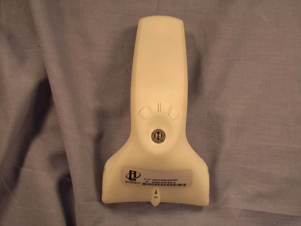
TK5-910EWWD
Sep 03, 2007Motion Tracker
Equipment Class
DTS - Digital Transmission System
TK5-IS9RX16
Sep 03, 2007Motion Tracker
Equipment Class
DTS - Digital Transmission System
TK5-IC3RX16
Apr 20, 2006Wireless InertiaCube3 Receiver
Equipment Class
DTS - Digital Transmission System
TK5-IMUW301
Apr 17, 2006Wireless InertiaCube3
Equipment Class
DTS - Digital Transmission System