TM4I707FM Transmitter with Car Adapter for iPod
Teleway Industrial Ltd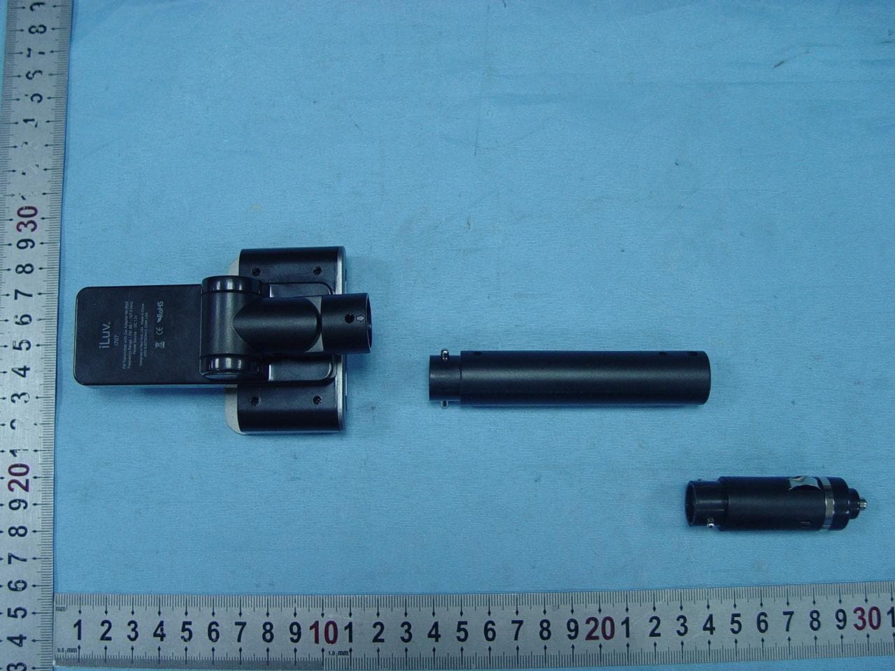
Click to zoom
Application Details
- Equipment Class
- DXX - Part 15 Low Power Communication Device Transmitter
- Date of Grant
- Sep 23, 2007
- Application Purpose
- Original Equipment
- Date of Application
- Sep 23, 2007
- Equipment Note
- FM Transmitter with Car Adapter for iPod
- Frequency Range
- 88.10000000 - 107.90000000
- Company
- Teleway Industrial Ltd
- Country
- China
Documents & Files
Document Text
Text extracted from the exhibit documents filed with the FCC. Open a document above to read the original.
Users Manual
Car Charger & FM Transmitter Instruction Manual i707 GETTING STARTED Thank you for purchasing the i707. Unpack the unit and make sure all the accessories are put aside so they will not be lost. Be Free from Headphones and Share Your Music with Your Friends. • Transmit your favorite songs on your iPod ® to a nearby FM radio • Supports the wide frequency range (88.1MHz to 107.9MHz) with the step size of 0.1MHz • Enjoy easy digital FM tuning with PLL technology • Preset memory for up to 2 FM stations • LCD screen with the white backlight • Compact and easy-to-use design • Car adapter charges your iPod What’s Included? • FM transmitter • Extension tube • Dock adapters • Instruction manual • Warranty card 1. 4. 2. 3. 5. 6. GETTING STARTED Location of Controls 1. λ (Preset 1) button 2. ∧(Frequency up) button 3. 30-pin connector 4. λλ (Preset 2) button 5. ∨(Frequency down) button 6. LCD screen Car adapter Extension tube Display board and dock Pin Hole Pin Hole OPERATING INSTRUCTIONS Connecting the extension tubes There are 2 pcs tubes included with the i707. The longer one is the extension tube which can be used as needed. One end of the extension is smaller and has pins while the other is wider and has an opening with two holes on either side. To connect the extension tube with the car adapter and the display board and dock, find the pins and holes on each part. Align the pins on each tube with the holes on the connecting end and insert. The tubes will “click” together when a successful connection has been made. 180° 35° OPERATING INSTRUCTIONS Adjusting the angle of FM transmitter The display board and dock can be adjusted up or down 180 degrees. The connector, which connects the display board and the extension tube, can adjust 35 degrees to the left or right allowing you to adjust the i707 for easy operation while driving. OPERATING INSTRUCTIONS Inserting the Dock Adapter The i707 comes with dock adapters for your iPod. There are also dock adapters included with your iPod. Choose the correct adapter and follow the instructions below. 1. Align the hooks in the back of the dock adapter with the holes on the dock above the display board. 2. Carefully lower the dock adapter until it rests securely in the dock with the 30 pin connector fitting through the opening at the bottom of the adapter. OPERATING INSTRUCTIONS Turning on / off the FM Transmitter This unit is designed to charge your iPod as it plays. When connected to your iPod and plugged into the cigarette lighter outlet in your car, it automatically turns on. When disconnected, it turns off. If there is no audio input signal for more than 1 minute after connected to your iPod, this unit enters the standby mode. In the standby mode, transmission stops and the LCD turns off. When there is an audio signal, it automatically “wakes up” to start transmitting music. Setting up the Preset Memory You can store two FM frequencies in the preset memoy and easily call them up by pressing one of the preset buttons. The default frequency for Preset 1 is 90.1MHz, and 98.1MHz for Preset 2. To change the default-preset frequencies with other frequencies, follow the instructions below: 1. Connect the FM transmitter to your iPod and plug into the cigarette lighter in your car. The LCD screen turns on. 2. Turn on the radio in your car and find an unused frequency on the FM dial. 3. Select a frequency using the “∧” (Frequency Up) and “∧”(Frequency Down) buttons. 4. Press and hold “λ” (Preset 1) button until the selected frequency display blinks. 5. Select a frequency using the “∧” (Frequency Up) and “∨” (Frequency Down) buttons. 6. Press and hold “λλ” (Preset 2) button until the selected frequency display blinks. OPERATING INSTRUCTIONS Transmitting Your Favorite Songs to a Nearby FM Radio 1. Connect the FM transmitter to your iPod. 2. Play songs from your iPod. 3. Press one of the preset buttons. 4. Turn on your car radio. 5. Tune your FM radio to a FM frequency stored on the selected preset memory, and listen to your favorite music. Warning: Do not listen to music with high volume while driving. Warning horn sounds may not be heard which could result in a traffic accident. Helpful Tips on Obtaining Clear Sound • An FM transmitter employs frequency modulation to transmit songs to an FM radio, which can be disturbed by a strong FM signal nearby. Thus, before transmitting songs with this unit, it is very important to select a clear FM station, one which has no other broadcasting and renders only static noise. • The sound quality of an FM transmitter also depends on the direction of its built-in antenna and its surroundings. If you hear static noises while listening to music using the FM transmitter, rotate or move the FM transmitter around until you get a clearer sound. • If a battery is low, the sound quality may also be poor. In this case, charge your iPod first and try it again. TROUBLESHOOTING GUIDE No sound • Your iPod is not inserted into the dock properly. Insert into the dock again. • Connection to car adapter is not secure. Check connections. • Your car radio is not turned on. Turn on your car radio. • Your iPod is not turned on. Turn on your iPod. • The i707 is not turned on. Turn on i707. Poor radio reception or interference • The i707 is tuned to a frequency that is used by a local radio station. Find a frequency with no interference and reset the memory. • The antenna on your car is not extended. Extend your car antenna. Car adapter does not fit into cigarette lighter • The lighter coil has not been removed. Remove the cigarette lighter coil and plug in car adapter. • The cigarette lighter is not standard size. The car adapter is designed to fit into the cigarette lighters of most makes and models of car. However, there may be some models with different sized cigarette lighters. SPECIFICATIONS • Modulation: FM Stereo • Tuning Type: PLL (Phase-Lock Loop) • Frequency Range: 88.1MHz – 107.9MHz (Step: 0.1MHz) • Frequency Response (Audio): 80Hz – 15kHz • A…
Text truncated - open the document above for the full version.
Block Diagram
1 2 3 4 56 ABCD 6 5 4 3 2 1 D CBA TitleCompany NameDesigned byApproved byVersionDate TELEWAY INDUSTRIAL LTDXu weiDavidV022007-7-20jwin_i707 LM2575 HD06 MCU_EM78153 HT1621 LCD AS6001 250V/2A 12 DC12V 12V-24V +5V 1A 123456789101112131415161718192021222324252627282930 CN1iPod 30PIN OUT ROUT L R11549K DC_3.3V 3.3V DATA CS WR ANT 7.6M FM_OUT RF _OUT
Cover Letter(s)
1. 4. 2. 3. 5. 6. Car adapter Extension tube Dis play board and dock Pin Hole Pin 1) How does this device operate? The FM transmitter is a FM stereo transmitting configuration, which radiates FM wave on the air by modulating the any required signal to the carrier signal. The transmission frequency is set 88.1MHz to 107.9MHz, frequency interval is 0.1MHz. Operating Instructions: Turning on / off the FM Transmitter This unit is designed to charge your iPod as it plays. When connected to your iPod and plugged into the cigarette lighter outlet in your car, it automatically turns on. When disconnected, it turns off. If there is no audio input signal for more than 1 minute after connected to your iPod, this unit enters the standby mode. In the standby mode, transmission stops and the LCD turns off. When there is an audio signal, it automatically “wakes up” to start transmitting music. Setting up the Preset Memory You can store two FM frequencies in the preset memoy and easily call them up by pressing one of the preset buttons. The default frequency for Preset 1 is 90.1MHz, and 98.1MHz for Preset 2. To change the default-preset frequencies with other frequencies, follow the instructions below: 1. Connect the FM transmitter to your iPod and plug into the cigarette lighter in your car. The LCD screen turns on. 2. Turn on the radio in your car and find an unused frequency on the FM dial. 3. Select a frequency using the “” (Frequency Up) and “ ”(Frequency Down) buttons.∧∧ 4. Press and hold “λ” (Preset 1) button until the selected frequency display blinks. 5. Select a frequency using the “” (Frequency Up) and “ ” (Frequency Down) buttons.∧∨ 6. Press and hold “λλ” (Preset 2) button until the selected frequency display blinks. Transmitting Your Favorite Songs to a Nearby FM Radio 1. Connect the FM transmitter to your iPod. 2. Play songs from your iPod. 3. Press one of the preset buttons. 4. Turn on your car radio. 5. Tune your FM radio to a FM frequency stored on the selected preset memory, and listen to your favorite music. 2) Provide information on the device and its antenna. The transmitter configuration: Car adapter Extension tube Display board and dock Pin Hole Pin Hole 1.• (Preset 1) button 2. (Frequency up) button∧ 3.30-pin connector 4. •• (Preset 2) button 5. (Frequency down) button∨ 6.LCD screen The transmitter utilizes a wire as dipole antenna. 3) How is it installed? Connecting the extension tubes There are 2 pcs tubes included with the i707. The longer one is the extension tube which can be used as needed. One end of the extension is smaller and has pins while the other is wider and has an opening with two holes on either side. To connect the extension tube with the car adapter and the display board and dock, find the pins and holes on each part. Align the pins on each tube with the holes on the connecting end and insert. The tubes will “click” together when a successful connection has been made. Antenna 180° 35° Adjusting the angle of FM transmitter The display board and dock can be adjusted up or down 180 degrees. The connector, which connects the display board and the extension tube, can adjust 35 degrees to the left or right allowing you to adjust the i707 for easy operation while driving. Inserting the Dock Adapter The i707 comes with dock adapters for your iPod. There are also dock adapters included with your iPod. Choose the correct adapter and follow the instructions below. 1. Align the hooks in the back of the dock adapter with the holes on the dock above the display board. 2. Carefully lower the dock adapter until it rests securely in the dock with the 30 pin connector fitting through the opening at the bottom of the adapter. 4) What test procedure was used? ANSI C63.4, the test was performed in a semi-anechoic chamber. 5) If tested in a car, how was it configured/tested? Not tested in a car, it was tested in a semi-anechoic chamber. The EUT has been additionally tested / verified and does work in a typical car. 6) Was the tuning range properly verified? The test lab should indicate in the report that the tuning controls were manually adjusted to verify maximum tuning range. The FM transmitter is a FM stereo transmitting configuration, which radiates FM wave on the air by modulating the any required signal to the carrier signal. The transmission frequency is set from 88.1 to 107.9MHz, frequency interval is 0.1MHz. We selected the low (88.1MHz) mid (98.1MHz) and High (107.9MHz) working frequency to measure the frequency. tune the knob to select the transmission frequency . We have indicated the testing in the test report, see clause 6. 7) Was the bandwidth properly tested with maximum audio input? The test was performed with the maximum audio input. And play typical audio signal (music song). We have indicated the operating condition in the test report, see clause 5.3.
ID Label/Location Info
ID label & location info. ID label location FCC ID:TM4I707
Operational Description
Operation Description Jwin_i707 Operation Frequency: 88.1M-107.9MHz Modulation Type: FM 1. The unit is supplied by external power 12V. The power goes through a fuse 250V/2A and polarity protection IC (HD06), further filtered and converted to a stable 5V by IC (LM2575). The 5V is input to pin 8 of the male 30PIN of iPod. The unit is in standby mode. 2. When iPod is inserted, it is charged by 5V and is switched on electronically. 5V is converted to 3.3V by IC to supply the unit. At the same time, the background light is on and to be dark off after 5 seconds. 3. MCU (EM78153) recalls memory 24C02 and sends frequency data of last use to HT1621. HT1621 drives LCD to display the frequency. At the same time, MCU switches on RF circuit and send frequency data to FM RF IC (AS6001) for transmission. 4. R&L of audio signal is filtered by low-pass filter. The signal is modulated and amplified to match network. It is transmitted by antenna. When no audio input, audio detecting circuit outputs a signal of level 1 to MCU. MCU counts time and will shut down the unit and LCD does not display after 60 seconds. The unit enters to standby mode. When audio input, audio detecting circuit outputs a pulse voltage to MCU, MCU will switch on and LCD displays the frequency of last transmission. 5. S1 and S3 are frequency + and – buttons. S2 and S4 are M1 and M2 memory buttons. Every button is pressed, MCU will control RF IC and HT1621 to display the same frequency of transmission. 6. When the external power is disconnected, the ipod is not charged and the background light is shut off. But the transmission frequency and the LCD display frequency will not be changed as the ipod supplies the unit.
Schematics
1 2 3 4 56 ABCD 6 5 4 3 2 1 D CBA C21 1UF C22 1UF C31102C32102 R31 7.5K R32 7.5K R30 47K R29 47K L_INR_IN 3 1 2 U6A1117-3.3 C11104 1234 JP14 HEADER C12104 + C42 100uF/4V L547uH C8104 VCC_3V R41 2.2ohm R42 2.2ohm Q39014 R13 220K C5 104 R14 47K R17 10M VCC_3V P60/INT 10 P61 9 P62 8 P63 7 P64 6 P65 5 P66 3 P67 2 P50 1 P51 14 P52 13 P53 12 VSS 11 VCC 4 U3 EM78153 MCU_VCC R35 10K MCU_VCC D4LED A0A1A2 VSS SDASCLNCVCC U524C02 MCU_VCC R1647K CS 1 WR 2 DATA 3 VSS 4 VLCD 5 VDD 6 LED 7 COM0 8 COM1 9 COM2 10 COM3 11 SEG31 12 SEG30 13 SEG29 14 SEG28 15 SEG27 16 SEG26 17 SEG25 18 U2 HT1621-A R12 3.3K COM1COM2COM3COM4 COM1COM2 COM3 COM4SEG25SEG26SEG27SEG28SEG29SEG30SEG31SEG25SEG26SEG27SEG28SEG29SEG30SEG31 VDD VDD CSWRDATA CS WRDATA AUDIO_CHK AUDIO_CHK C6 104 C4104 S1Up S2 Mem1 S3 Down FM_PW R15 47K L3 560NH VSSD 1 RCH 2 VDDD 3 RF_VDD 4 VDDH 5 RF_VSS 6 VPLL 7 MOD_OUT 8 RF_OUT 9 LC_OUT 10 XI 11 RST 12 XO 13 SEL 14 EN 15 CLK 16 DATA 17 NC 18 LCH 19 PDN 20 U1AS6001 CV1 KV1471 L1 100nH C191UF C28473 C201UF C30 10U C2630P Y1 7.6M C1427P C15 27P C16 1UF C17 1UF VCC_RF VCC_RF C222U/4V C23103 C34102 E1 ANTENNA C24103 C33 102 L2 2.2uH Q59018 C2747P C3547P R3647K R193.3K R710K R610K R810K R201.91K R1815K R92.2ohm L_IN R_IN DATAEN R4 10K R5 10K R102.2ohm R370ohm R3810K C36 3.3uF C18 1UF SET SET R14.7K VCC_3V FM_PW C122U/4V C3104 Q19015 R211.91K C29 473 C13104 + C43 47uF/4V R22 43.2K 1% R2875.0K 1% R23 49.9K 1% R24 49.9K 1% L4 220uH D35819 + C39470uF/6.3V + C40 100uF/6.3V VCC_5V + C41 47uF/6.3V C10104 C25 104 + C37 100uF/35V EN WR 123456789 101112131415161718192021222324252627282930 CN1 iPod DOCK JACK OUT ROUT L OUT ROUT L D5 5.8V R11549K COM0 1 COM1 2 COM2 3 COM3 4 SEG1 5 SEG2 6 SEG3 7 SEG4 8 SEG5 9 SEG6 10 SEG7 11 SEG8 12 LCD1 LCD SEG24 SEG24 Q29015 R35.6K F/W GND F/W GND S4 Mem2 1 2 3 4 JP2HD06 R430.5ohm D6 5817 VCC_3.3V A Q68050 R44560ohm R45220ohm D75817 ipod_3.3V ipod_3.3V MCU_VCC TitleCompany NameDesigned byApproved byVersionDate TELEWAY INDUSTRIAL LTDXu weiDavidV022007-7-20jwin_i707 C45104 C9104 IN 1 OUT 2 GND 3 FEEDBACK 4 ON/OFF 5 U4 LM2575 D2LED R45680ohm R46680ohm A
Test Report
Page 1 of 29 FCC ID: TM4I707 ACCURATE TECHNOLOGY CO. LTD REPORT NO. ATE20072089 FCC CERTIFICATION On Behalf of Teleway Industrial Ltd. FM Transmitter with Car Adapter for iPod Model No.: i707 FCC ID: TM4I707 Prepared for : Teleway Industrial Ltd. Address : 5/F., Block 40, Ma Jia Long Industrial Area, Nanshan District, Shenzhen, 518052, Guangdong Province, China Prepared by : Accurate Technology Co., Ltd. Address : F1, Bldg. A, Changyuan New Material Port, Keyuan Rd. Science & Industry Park, Nanshan, Shenzhen, Guangdong P.R. China Tel: (0755) 26503290 Fax: (0755) 26503396 Report Number : ATE20072089 Date of Test : September 07, 2007 Date of Report : September 20, 2007 Page 2 of 29 FCC ID: TM4I707 ACCURATE TECHNOLOGY CO. LTD REPORT NO. ATE20072089 TABLE OF CONTENTS Description Page Test Report Certification 1. GENERAL INFORMATION .......................................................................................................... 4 1.1. Description of Device (EUT)....................................................................................................................4 1.2. Description of Test Facility ......................................................................................................................4 1.3. Measurement Uncertainty.........................................................................................................................4 2. MEASURING DEVICE AND TEST EQUIPMENT ..................................................................... 5 3. RADIATED EMISSION FOR FCC PART 15 SECTION 15.239(C)........................................... 6 3.1. Block Diagram of Test Setup....................................................................................................................6 3.2. The Emission Limit for section 15.239(c) ................................................................................................6 3.3. Configuration of EUT on Measurement ...................................................................................................7 3.4. Operating Condition of EUT ....................................................................................................................7 3.5. Test Procedure ..........................................................................................................................................7 3.6. The Field Strength of Radiation Emission Measurement Results ............................................................8 4. FUNDAMENTAL RADIATED EMISSION FOR FCC PART 15 SECTION 15.239(B) ........ 11 4.1. Block Diagram of Test Setup..................................................................................................................11 4.2. The Emission Limit For Section 15.239(b) ............................................................................................11 4.3. EUT Configuration on Measurement .....................................................................................................12 4.4. Operating Condition of EUT ..................................................................................................................12 4.5. Test Procedure ........................................................................................................................................12 4.6. The Emission Measurement Result ........................................................................................................13 5. OCCUPIED BANDWIDTH FOR FCC PART 15 SECTION 15.239(A) ................................... 16 5.1. The Requirement For Section 15.239(a).................................................................................................16 5.2. EUT Configuration on Measurement .....................................................................................................16 5.3. Operating Condition of EUT ..................................................................................................................16 5.4. Test Procedure ........................................................................................................................................16 5.5. Test Result ..............................................................................................................................................17 6. TUNING RANGE ........................................................................................................................... 18 6.1. The Requirement For Section 15.239 .....................................................................................................18 6.2. EUT Configuration on Measurement .....................................................................................................18 6.3. Operating Condition of EUT ..................................................................................................................18 6.4. Test Procedure ........................................................................................................................................18 6.5. Test Result ..............................................................................................................................................19 APPENDIX I ( TEST CURVES) (9 pages) Page 3 of 29 FCC ID: TM4I707 ACCURATE TECHNOLOGY CO. LTD REPORT NO. ATE20072089 Test Report Certification Applicant : Teleway Industrial Ltd. Manufacturer : jWIN Electronics Corp., USA EUT Description : FM Transmitter with Car Adapter for iPod (A) MODEL NO.: i707 (B) SERIAL NO.: N/A (C) POWER SUPPLY: DC 12V (Power by Car battery) Measurement Procedure Used: FCC Rules and Regulations Part 15 Subpart C Section 15.239: 2006& ANSI 63.4: 2003 The device described above is tested by ACCURATE TECHNOLOGY CO. LTD to determine the maximum emission levels emanating from the device. The maximum emission levels are compared to the FCC Part 15 Subpart C Section15.239 limits. The measurement results are contained in this test report and ACCURATE TECHNOLOGY CO. LTD is a…
Text truncated - open the document above for the full version.
Contact Information
Applicant
Lion Liao(Approbation Engineer)
Test Firm
Accurate Technology Co., Ltd.Sean Liu
Technical Specifications
| # | Rule Parts | Frequency Range | Power Output |
|---|---|---|---|
| 1 | 15C | 88.1 MHz - 107.9 MHz | - |
Other Applications from Teleway Industrial Ltd
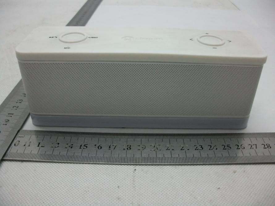
TM4-DEA059
Nov 07, 2013Bluetooth Speaker
Equipment Class
DXX - Part 15 Low Power Communication Device Transmitter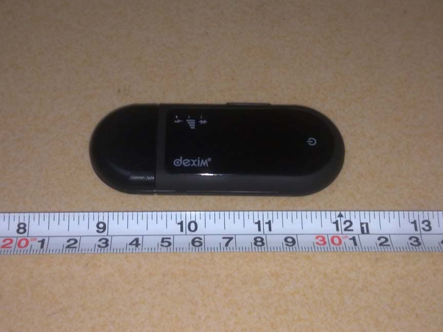
TM4-DFU026
Oct 29, 2012GrooveStikTM Wireless Audio Solution
Equipment Class
DSS - Part 15 Spread Spectrum Transmitter
TM4DVA006
Oct 11, 2012ClickStik Bluetooth Remote
Equipment Class
DSS - Part 15 Spread Spectrum TransmitterTM4-DVA009
Oct 10, 2012CAMERA FOR ANDROID
Equipment Class
DSS - Part 15 Spread Spectrum Transmitter
TM4DXA022
Jun 14, 2012Bluetooth remote control car
Equipment Class
DSS - Part 15 Spread Spectrum Transmitter