TM4TMP3FT-FSFull FM Transmitter w/LCD
Teleway Industrial Ltd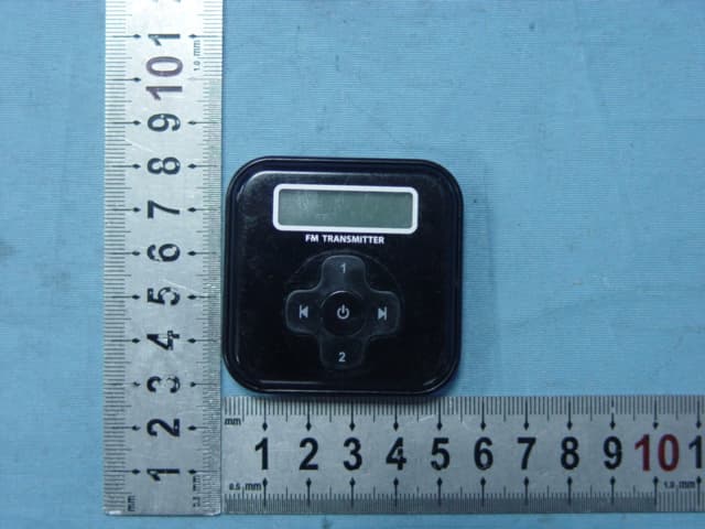
Click to zoom
Application Details
- Equipment Class
- DXX - Part 15 Low Power Communication Device Transmitter
- Date of Grant
- Sep 19, 2007
- Application Purpose
- Original Equipment
- Date of Application
- Sep 19, 2007
- Equipment Note
- Full FM Transmitter w/LCD
- Frequency Range
- 88.10000000 - 107.90000000
- Company
- Teleway Industrial Ltd
- Country
- China
Documents & Files
Document Text
Text extracted from the exhibit documents filed with the FCC. Open a document above to read the original.
Users Manual
FM Transmitter Instruction Manual TMP3FT-FS(JA-CK703) GETTING STARTED Thank you for purchasing the JA-CK703. Unpack the unit and make sure all the accessories are put in a place where they will not be lost. Be Free from Headphones and Share Your Music with Your Friends. 1. LCD display for transmit frequency with blue backlight 2. Compatible with all iPod/MP3 models. PSP and any devices with headphone output 3. Frequency range: 88.1MHz to 107.9MHz (step: 0.1MHz) 4. Operation range: 33 ft (10 meters) 5. Audio Defect function (after 1 min goes to standby if no signal is detected) 6. 2 preset memory frequencies 7. One step search & fast search 8. Last frequency memory 9. Power source: 1xAAA battery (1.5V). What’s Included? • FM transmitter • 1x 3.5mm to 3.5mm audio cable (length: 20cm) • Instruction manual OPERATING INSTRUCTIONS Descriptions: Connecting with all iPod models, PSP, MP3 players: 1. Insert one AAA battery into battery compartment of transmitter. 2. Insert one end of the supplied connection cable into Transmitter’s audio jack 3. Insert the other end of cable into your iPod/PSP/MP3’s headphone output jack Listening to music: 1. Turn on your car radio or home radio and select a suitable frequency (eg.88.1MHz). 2. Press ⑤ for 3 seconds to turn on the FM Transmitter. 3. Press ③ or ④ to select the frequency as same as radio’s (eg.88.1MHz). 4. Turn on the connected MP3 player. 5. Check signal quality, in case that quality is not satisfactory, try turn to a suitable FM Frequency. 6. Press and hold (3 seconds) the ① or ② buttons to save the current frequency. SPECIFICATIONS • Modulation: FM Stereo • Frequency Ranges: 88.1MHz - 107.9MHz (step: 0.1MHz) • Operating Range: 33 ft (10 meters) • Power Source o 1 x “AAA” battery • Unit Dimensions (W x H x D): o 2” x 2” x 0.58” (52.5mm x52.5mm x14.7mm) FCC Statement 1. This device complies with Part 15 of the FCC Rules. Operation is subject to the following two conditions: (1) This device may not cause harmful interference, and (2) This device must accept any interference received, including interference that may cause undesired operation. 2. Changes or modifications not expressly approved by the party responsible for compliance could void the user’s authority to operate the equipment.
Cover Letter(s)
1) How does this device operate? The FM transmitter is a FM stereo transmitting configuration, which radiates FM wave on the air by modulating the any required signal to the carrier signal. The transmission frequency is set 88.1MHz to 107.9MHz, frequency interval is 0.1MHz. Operating Instructions: Connecting with all iPod models, PSP, MP3 players: 1.Insert one AAA battery into battery compartment of transmitter. 2.Insert one end of the supplied connection cable into Transmitter’s audio jack 3.Insert the other end of cable into your iPod/PSP/MP3’s headphone output jack Listening to music: 1.Turn on your car radio or home radio and select a suitable frequency (eg.88.1MHz). 2.Press for 3 seconds to turn on the FM Transmitter.⑤ 3.Press ③ or to sele④ct the frequency as same as radio’s (eg.88.1MHz). 4.Turn on the connected MP3 player. 5.Check signal quality, in case that quality is not satisfactory, try turn to a suitable FM Frequency. Press and hold (3 seconds) the or ①②buttons to save the current frequency. 2) Provide information on the device and its antenna. The transmitter has seven parts: memory button, forward frequency knob, 3.5mm audio jack, backward frequency knob, on-off switch, LCD display and battery box. The transmitter utilizes a wire as dipole antenna. 3) How is it installed? The transmitter is powered by 1 ̄ AAA batteries. It can be connected to audio source headphone dock. 4) What test procedure was used? ANSI C63.4, the test was performed in a semi-anechoic chamber. 5) If tested in a car, how was it configured/tested? Not tested in a car, it was tested in a semi-anechoic chamber. The EUT has been additionally tested / verified and does work in a typical car. 6) Was the tuning range properly verified? The test lab should indicate in the report that the tuning controls were manually adjusted to verify maximum tuning range. Antenna The FM transmitter is a FM stereo transmitting configuration, which radiates FM wave on the air by modulating the any required signal to the carrier signal. The transmission frequency is set from 88.1 to 107.9MHz, frequency interval is 0.1MHz. We selected the low (88.1MHz) mid (98.1MHz) and High (107.9MHz) working frequency to measure the frequency. tune the knob to select the transmission frequency . We have indicated the testing in the test report, see clause 6. 7) Was the bandwidth properly tested with maximum audio input? The test was performed with the maximum audio input. And play typical audio signal (music song). We have indicated the operating condition in the test report, see clause 5.3.
ID Label/Location Info
ID label & location info. ID label location FCC ID:TM4TMP3FT-FS
Operational Description
Operation Description TMP3FT-FS(Jack-703) Operation Frequency: 88.1M-107.9MHz Modulation Type: FM 1. The unit may be powered by a battery (DC1.5V). Internal DC/DC circuit increases voltage to 3.3V to supply the unit. The unit is in standby mode this moment. 2. When long press “POWER” button 3 seconds, MCU switches on electronically and supply local oscillating circuit and amplifier. The background light is on and to shut off after 5 seconds. MCU recalls the frequency of last use from PLL (31202) and HT1621. 3. R&L of audio signal is filtered by low-pass filter. One is input to local oscillating circuit. The other is input to MCU and is processed to output to local oscillating circuit too. The signal is modulated and amplified to match network. Its harmonics is filtered and it is transmitted by antenna. When no audio input, audio detecting circuit outputs a signal of level 1 to MCU. MCU counts time and will shut down the unit and LCD does not display after 60 seconds. The unit enters to standby mode. When audio input, audio detecting circuit outputs a pulse voltage to MCU, MCU will switch on and LCD displays the frequency of last transmission. 4. S1 and S3 are frequency + and – buttons. S2 and S4 are M1 and M2 memory buttons. Every button is pressed, MCU will control PLL IC and HT1621 to display the same frequency of transmission. At the same time, background is light on and to shut off after 5 seconds.
Test Report
Page 1 of 29 FCC ID: TM4TMP3FT-FS ACCURATE TECHNOLOGY CO. LTD REPORT NO. ATE20072199 FCC CERTIFICATION On Behalf of Teleway Industrial Ltd. Full FM Transmitter w/LCD Model No.: TMP3FT-FS(JA-CK703) FCC ID: TM4TMP3FT-FS Prepared for : Teleway Industrial Ltd. Address : 5/F., Block 40, Ma Jia Long Industrial Area, Nanshan District, Shenzhen, 518052, Guangdong Province, China Prepared by : Accurate Technology Co., Ltd. Address : F1, Bldg. A, Changyuan New Material Port, Keyuan Rd. Science & Industry Park, Nanshan, Shenzhen, Guangdong P.R. China Tel: (0755) 26503290 Fax: (0755) 26503396 Report Number : ATE20072199 Date of Test : September 07, 2007 Date of Report : September 12, 2007 Page 2 of 29 FCC ID: TM4TMP3FT-FS ACCURATE TECHNOLOGY CO. LTD REPORT NO. ATE20072199 TABLE OF CONTENTS Description Page Test Report Certification 1. GENERAL INFORMATION .......................................................................................................... 4 1.1. Description of Device (EUT)....................................................................................................................4 1.2. Description of Test Facility ......................................................................................................................4 1.3. Measurement Uncertainty.........................................................................................................................4 2. MEASURING DEVICE AND TEST EQUIPMENT ..................................................................... 5 3. RADIATED EMISSION FOR FCC PART 15 SECTION 15.239(C)........................................... 6 3.1. Block Diagram of Test Setup....................................................................................................................6 3.2. The Emission Limit for section 15.239(c) ................................................................................................6 3.3. Configuration of EUT on Measurement ...................................................................................................7 3.4. Operating Condition of EUT ....................................................................................................................7 3.5. Test Procedure ..........................................................................................................................................7 3.6. The Field Strength of Radiation Emission Measurement Results ............................................................8 4. FUNDAMENTAL RADIATED EMISSION FOR FCC PART 15 SECTION 15.239(B) ........ 11 4.1. Block Diagram of Test Setup..................................................................................................................11 4.2. The Emission Limit For Section 15.239(b) ............................................................................................11 4.3. EUT Configuration on Measurement .....................................................................................................12 4.4. Operating Condition of EUT ..................................................................................................................12 4.5. Test Procedure ........................................................................................................................................12 4.6. The Emission Measurement Result ........................................................................................................13 5. OCCUPIED BANDWIDTH FOR FCC PART 15 SECTION 15.239(A) ................................... 16 5.1. The Requirement For Section 15.239(a).................................................................................................16 5.2. EUT Configuration on Measurement .....................................................................................................16 5.3. Operating Condition of EUT ..................................................................................................................16 5.4. Test Procedure ........................................................................................................................................16 5.5. Test Result ..............................................................................................................................................17 6. TUNING RANGE ........................................................................................................................... 18 6.1. The Requirement For Section 15.239 .....................................................................................................18 6.2. EUT Configuration on Measurement .....................................................................................................18 6.3. Operating Condition of EUT ..................................................................................................................18 6.4. Test Procedure ........................................................................................................................................18 6.5. Test Result ..............................................................................................................................................19 APPENDIX I ( TEST CURVES) (9 pages) Page 3 of 29 FCC ID: TM4TMP3FT-FS ACCURATE TECHNOLOGY CO. LTD REPORT NO. ATE20072199 Test Report Certification Applicant : Teleway Industrial Ltd. Manufacturer : Teleway Industrial Ltd. EUT Description : Full FM Transmitter w/LCD (A) MODEL NO.: TMP3FT-FS(JA-CK703) (B) SERIAL NO.: N/A (C) POWER SUPPLY: DC 1.5V (AAA Battery ̄1) Measurement Procedure Used: FCC Rules and Regulations Part 15 Subpart C Section 15.239: 2006& ANSI 63.4: 2003 The device described above is tested by ACCURATE TECHNOLOGY CO. LTD to determine the maximum emission levels emanating from the device. The maximum emission levels are compared to the FCC Part 15 Subpart C Section15.239 limits. The measurement results are contained in this test report and ACCURATE TECHNOLOGY C…
Text truncated - open the document above for the full version.
Contact Information
Applicant
Lion Liao(Approbation Engineer)
Test Firm
Accurate Technology Co., Ltd.Sean Liu
Technical Specifications
| # | Rule Parts | Frequency Range | Power Output |
|---|---|---|---|
| 1 | 15C | 88.1 MHz - 107.9 MHz | - |
Other Applications from Teleway Industrial Ltd
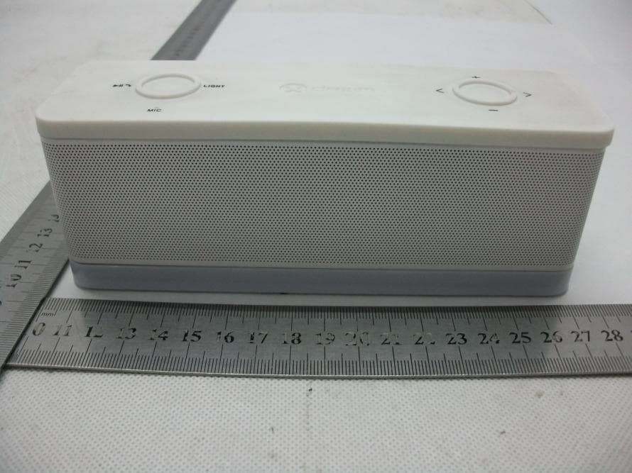
TM4-DEA059
Nov 07, 2013Bluetooth Speaker
Equipment Class
DXX - Part 15 Low Power Communication Device Transmitter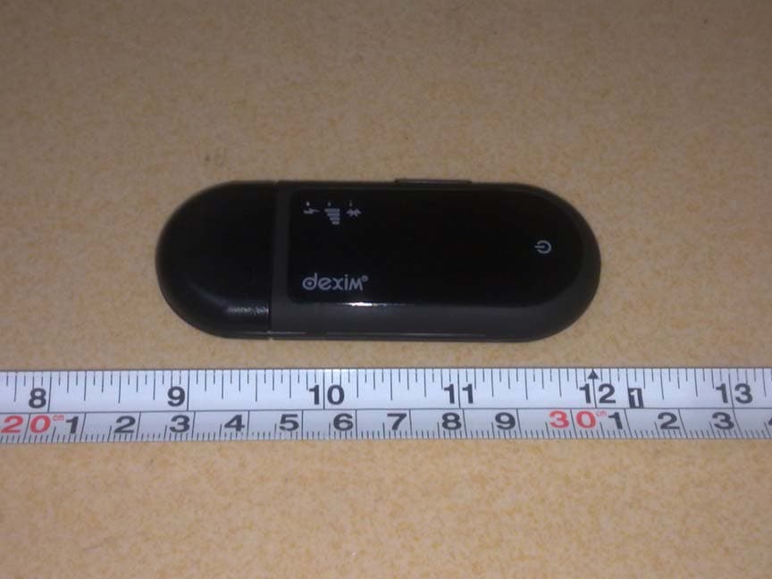
TM4-DFU026
Oct 29, 2012GrooveStikTM Wireless Audio Solution
Equipment Class
DSS - Part 15 Spread Spectrum Transmitter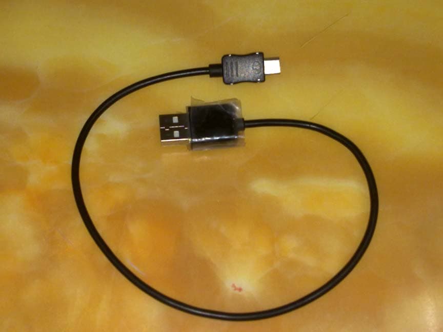
TM4DVA006
Oct 11, 2012ClickStik Bluetooth Remote
Equipment Class
DSS - Part 15 Spread Spectrum TransmitterTM4-DVA009
Oct 10, 2012CAMERA FOR ANDROID
Equipment Class
DSS - Part 15 Spread Spectrum Transmitter
TM4DXA022
Jun 14, 2012Bluetooth remote control car
Equipment Class
DSS - Part 15 Spread Spectrum Transmitter