TM4TMP3FTGFM Transmitter
Teleway Industrial Ltd
Click to zoom
Application Details
- Equipment Class
- DXX - Part 15 Low Power Communication Device Transmitter
- Date of Grant
- Oct 17, 2006
- Application Purpose
- Original Equipment
- Date of Application
- Oct 17, 2006
- Equipment Note
- FM Transmitter
- Frequency Range
- 89.10000000 - 107.90000000
- Company
- Teleway Industrial Ltd
- Country
- China
Documents & Files
Document Text
Text extracted from the exhibit documents filed with the FCC. Open a document above to read the original.
Users Manual
TELEWAY INDUSTRIAL LTD Http://www.teleway-ind.com Shenzhen factory : 5/F, Block 40, Ma Jialong Industrial Area, Nanshan District, Shenzhen,518052,Guangdong Province, PRC Tel: 86-755-26611059, Fax: 86-755-26611069 FM Transmitter INSTRUCTION MANUAL Instructions: 1. Open the battery compartment located on the bottom of the unit. 2. Insert 2 AAA 1.5V alkaline batteries (not included) following the diagram on the battery compartment cover. 3. Close the battery compartment. 4. Connect the audio input cord of the CD Auto Adapter to the headphone jack or line out jack of your portable CD/MP3 player. The line out jack is preferred, if your portable CD/MP3 player has one. 5. Push the Power ON/OFF switch on the CD Auto Adapter to the ON position. The lighted red LED light indicates power is on. 6. Set the FM band selector switch on the CD Auto Adapter to the range for the FM radio setting used on your car radio. 7. Turn on the power of the portable CD player and set the volume to a medium level. Note: the CD Auto Adapter does not provide power for your CD/MP3 player. Therefore, batteries (not included) must be installed in your CD/MP3 player. 8. Turn the Vehicle’s radio to medium volume, then slowly tune through the FM station range previously selected until you hear the music coming from your CD/MP3 player. Note: For optimum performance, it is batter for your radio to be set to an open frequency so there will be not interference from other FM stations. This may require very slight fine tuning, using the Tuning Wheel located on the side of the adapter. This procedure may take a few minutes the first time. However, simply setting one of your preset buttons for your selected station will eliminate the need to repeat the process. 9. Adjust the volume of your music source to a distortion free level. You can increase the volume of your car radio as necessary for desired sound level. Note: While driving your car and listening to the CD auto adapter, it is possible that interference from nearby stations may cause your reception fade out. If you hear this happening, adjust the Tuning Wheel. The Tuning Wheel is very sensitive. Move it slightly and you can restore your reception. Warning: Note: This equipment has been tested and found to comply with the limits for a Class B digital device, pursuant to part 15 of the FCC Rules. These limits are designed to provide reasonable protection against harmful interference in a residential installation. This equipment generates, uses and can radiate radio frequency energy and, if not installed and used in accordance with the instructions, may cause harmful interference to radio communications. However, there is no guarantee that interference will not occur in a particular installation. If this equipment does cause harmful interference to radio or television reception, which can be determined by turning the equipment off and on, the user is encouraged to try to correct the interference by one or more of the following measures: —Reorient or relocate the receiving antenna. —Increase the separation between the equipment and receiver. —Connect the equipment into an outlet on a circuit different from that to which the receiver is connected. —Consult the dealer or an experienced radio/TV technician for help. Modifications not authorized by the manufacturer may void users’ authority to operate this device
Cover Letter(s)
Teleway FM transmitter can be grant. Daniel From: EASTECH [mailto:[email protected]] Sent: 2006年10月18日 5:43 To: Document Control; EASTECH; Rashmi Doshi; Raymond Laforge Cc: [email protected]; [email protected]; [email protected] Subject: RE: Teleway FM Transmitter FCC ID:TM4TMP3FTG (Quick review and approval) Hello BACL, Yes, Go ahead and file. Thanks -----Original Message----- From: Document Control [mailto:[email protected]] Sent: Monday, October 16, 2006 1:09 PM To: EASTECH Cc: [email protected]; [email protected]; [email protected] Subject: Re: Teleway FM Transmitter FCC ID:TM4TMP3FTG (Quick review and approval) Hello FCC, We have followed the guidance at the TCB conference to submit with this request. As far as I know, base on the TCB conference call on September 12, 2006, TCB need to include these information below to FCC for quick review prior to grant issuing a grant . I have included the rar file/zip file with reponses on the question and test report in word and pdf format. 1) How does this device operate? 2) Provide information on the device and its antenna. 3) How is it installed? 4) What test procedure was used? 5) If tested in a car, how was it configured/tested? 6) Was the tuning range properly verified? The test lab should indicate in the report that the tuning controls were manually adjusted to verify maximum tuning range. 7) Was the bandwidth properly tested with maximum audio input? 8) Provide the test report. Please review the test report and the document. If there are updated guidance that I need to follow, please let me know. Besides, can you provide a FCC representative's name and phone number so that I can contact if anything happens or missing on this case? Thank you so much for your assistance, and I look forward to hearing from you soon. Best Regards, Document Control Bay Area Compliance Laboratories Corp. (408) 732-9162 ext. 3201 ----- Original Message ----- From: EASTECH To: Document Control ; EASTECH Cc: [email protected] ; [email protected] ; [email protected] Sent: Monday, October 16, 2006 8:04 AM Subject: RE: Teleway FM Transmitter FCC ID:TM4TMP3FTG (Quick review and approval) Hello DC at BACL, We have given guidance at the TCB conference on what you need to do and what needs to be submitted with this request. Please review the guidance and resubmit all required information in order for us to evaluate. Thanks -----Original Message----- From: Document Control [mailto:[email protected]] Sent: Friday, October 13, 2006 1:18 PM To: EASTECH Cc: [email protected] ; [email protected]; [email protected] Subject: Teleway FM Transmitter FCC ID:TM4TMP3FTG (Quick review and approval) Importance: High To Whom It May Concern in FCC: I am the Document Control in the Bay Area Compliance Laboratory Corp. We are requesting to grant the FM Transmitters with testing following with FCC Section 15.239 rule and guidance. Base on the TCB conference call on September 12, 2006, TCB must contact FCC prior to grant issuing a grant and FCC want to do a quick review of the test report. I have attached a package in this email with the test report, technical documents and response on the quick review. Please review the test report and the document. If there is any question or issue, please let me know. Thank you so much for your assistance, and I look forward to hearing from you soon. Best Regards, Document Control Bay Area Compliance Laboratories Corp. (408) 732-9162 ext. 3201
External Photos
EXHIBIT B - EUT PHOTOGRAPHS EUT – Front View EUT – Rear View
ID Label/Location Info
EXHIBIT A - FCC ID LABELING AND LOCATION Proposed FCC ID Labeling Proposed FCC ID Location FCC ID Label Location FCC ID: TM4TMP3FTG
Internal Photos
EXHIBIT C - EUT INTERNAL PHOTOGRAPHS EUT – Inside View EUT – PCB View (1) EUT –PCB View (2) EUT –PCB View (3)
Operational Description
Specifications for PVC Full Frequency FM Transmitter 1. Frequency range: 89.0MHz- 107.9MHz. It can be divided into three parts, and can be adjusted up or down by 0.1MHz. 2. Working mode: FM (Frequency Modulation). 3. There are inside antenna and outside antenna for this item. The outside antenna use the ground cable of connecting cable of transmitter and player, and the length of connecting cable is over 20cm. 4. This item is powered by 2 AAA batteries (3V).
Schematics
1 2 3 4 56 ABCD 6 5 4 3 2 1 D CBA C3722P C44202 C45 10P S3FRQ SW R_IN 1 AF_BIAS 2 AF_GND 3 OSC_BIAS 4 XTAL1 5 XTAL2 6 RF_OUT 7 RF_GND 8 OSC1 9 L_IN 18 MPX_BAL2 17 MPX_BAL1 16 VCC 15 MPX_OUT 14 PILOT_OUT 13 MOD_IN 12 V_REF 11 OSC2 10 U3 BA1404 R2068K R30220K R194.7K S2SW 2P + C30 10uF/6.3V R183.3K C29102 L12 8.5T/D=2/d=0.3 C40220 123 CP2AUDIO_IN + C39 10uF/6.3V C5015P C5110P R31150 BT1BATT + C41220uF/6.3V R2922K TC1pvc107F + C3310uF/6.3V C522P + C42 10uF/6.3V C4925P C32102 R223.3K L155.6uH R2110 C483P R2468K C43102 L16 2.5T/D=4/d=0.6 R234.7K C4739P X238K D4 LED R1722K R1622K FRQ1 FRQ2 FRQ3 R305.1 1 2 3 U?BPF C40390p
Test Report
Note: The test report is specially limited to the above company and this particular sample only. It may not be duplicated without prior written consent of Bay Area Compliance Lab Corp. (ShenZhen). This report must not be used by the client to claim product certification, approval, or endorsement by NVLAP, NIST or any agency of the US Government. FCC PART 15.239 EMI MEASUREMENT AND TEST REPORT For TELEWAY INDUSTRIAL LTD 5/F , Block 40,MaJialong Industrial Area,Nanshan District,Shenzhen,518052,Guangdong Province,PRC FCC ID: TM4TMP3FTG September 15, 2006 This Report Concerns: Original Report Equipment Type: FM TRANSMITTER Test Engineer: Charmi Peng Report No.: RSZ06082901 Test Date: September 14, 2006 Reviewed By: Boni Baniqued Prepared By: Bay Area Compliance Lab Corp. (ShenZhen) 6/F, the 3rd Phase of WanLi Industrial Building, ShiHua Road, FuTian Free Trade Zone, ShenZhen, Guangdong 518038, P.R.China Tel: +86-755-33320018 Fax: +86-755-33320008 TELEWAY INDUSTRIAL LTD FCC ID: TM4TMP3FTG Report # RSZ06082901 Page 2 of 17 FCC Part 15.239 Test Report TABLE OF CONTENTS GENERAL INFORMATION.......................................................................................................................................3 PRODUCT DESCRIPTION FOR EQUIPMENT UNDER TEST (EUT) ....................................................................................3 OBJECTIVE...................................................................................................................................................................3 RELATED SUBMITTAL(S)/GRANT(S).............................................................................................................................3 TEST METHODOLOGY..................................................................................................................................................3 TEST FACILITY.............................................................................................................................................................3 LOCAL SUPPORT EQUIPMENT LIST AND DETAILS........................................................................................................4 EXTERNAL I/O CABLE..................................................................................................................................................4 SYSTEM TEST CONFIGURATION ..........................................................................................................................5 JUSTIFICATION.............................................................................................................................................................5 EUT EXERCISE SOFTWARE..........................................................................................................................................5 SPECIAL ACCESSORIES.................................................................................................................................................5 EQUIPMENT MODIFICATIONS.......................................................................................................................................5 CONFIGURATION OF TEST SETUP.................................................................................................................................6 BLOCK DIAGRAM OF TEST SETUP................................................................................................................................6 SUMMARY OF TEST RESULTS ...............................................................................................................................7 §15.203 - ANTENNA REQUIREMENT......................................................................................................................8 STANDARD APPLICABLE..............................................................................................................................................8 §15.209 AND §15.239- RADIATED EMISSION ........................................................................................................9 MEASUREMENT UNCERTAINTY....................................................................................................................................9 EUT SETUP..................................................................................................................................................................9 EMI TEST RECEIVER SETUP.......................................................................................................................................10 TEST EQUIPMENT LIST AND DETAILS.........................................................................................................................10 TEST PROCEDURE......................................................................................................................................................10 CORRECTED AMPLITUDE & MARGIN CALCULATION.................................................................................................10 TEST RESULTS SUMMARY..........................................................................................................................................10 TEST DATA................................................................................................................................................................11 §15.239(A) –EMISSION BANDWIDTH ...................................................................................................................13 STANDARD APPLICABLE.............................................................................................................................................13 TEST PROCEDURE......................................................................................................................................................13 TEST EQUIPMENT LIST AND DETAILS........................................................................................................................…
Text truncated - open the document above for the full version.
Test Setup Photos
EXHIBIT D - TEST SETUP PHOTOGRAPHS Radiated Emission - Front View Radiated Emission - Rear View
Contact Information
Applicant
Lion Liao(Approbation Engineer)
Test Firm
Bay Area Compliance Laboratory Corp. (Shenzhen)John Chan
Technical Specifications
| # | Rule Parts | Frequency Range | Power Output |
|---|---|---|---|
| 1 | 15C | 89.1 MHz - 107.9 MHz | - |
Other Applications from Teleway Industrial Ltd
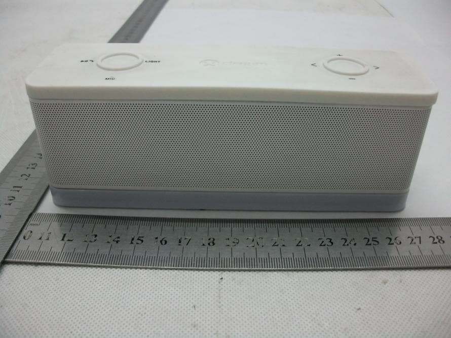
TM4-DEA059
Nov 07, 2013Bluetooth Speaker
Equipment Class
DXX - Part 15 Low Power Communication Device Transmitter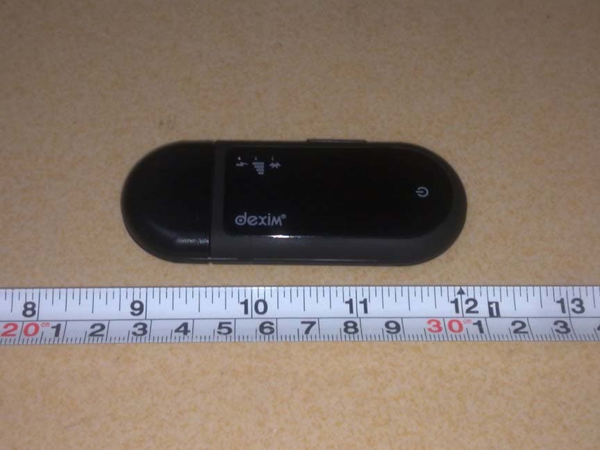
TM4-DFU026
Oct 29, 2012GrooveStikTM Wireless Audio Solution
Equipment Class
DSS - Part 15 Spread Spectrum Transmitter
TM4DVA006
Oct 11, 2012ClickStik Bluetooth Remote
Equipment Class
DSS - Part 15 Spread Spectrum TransmitterTM4-DVA009
Oct 10, 2012CAMERA FOR ANDROID
Equipment Class
DSS - Part 15 Spread Spectrum Transmitter
TM4DXA022
Jun 14, 2012Bluetooth remote control car
Equipment Class
DSS - Part 15 Spread Spectrum Transmitter