TMY-BTM-002Bluetooth Headset
BT-Links Company Limited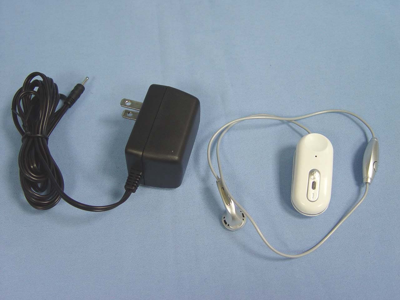
Click to zoom
Application Details
- Equipment Class
- DSS - Part 15 Spread Spectrum Transmitter
- Date of Grant
- Mar 27, 2006
- Application Purpose
- Original Equipment
- Date of Application
- Mar 27, 2006
- Equipment Note
- Bluetooth Headset
- Frequency Range
- 2402.00000000 - 2480.00000000
- Company
- BT-Links Company Limited
- Country
- Hong Kong
Documents & Files
Document Text
Text extracted from the exhibit documents filed with the FCC. Open a document above to read the original.
Users Manual
BTM-002 Bluetooth Headset User Guide Please follow the simple steps to operate the Bluetooth headset : Battery Charging 1. Turn off the headset. 2. Connect the charger to the main power and plug the adaptor to the charging socket of the headset. 3. During charging, the LED will turn red. When the battery is fully charged, the LED will be off. 4. Disconnect the charger from the main power and the headset. BT-200 Headset Overview Remark : If the headset is not used for a long time or the battery is drained, the indication of charging (red LED) will be displayed a few seconds later Charging Time The headset is equipped with a built-in rechargeable battery. For the first time of use, please charge the battery for 14 hours. Thereafter, the battery charging time is normally within 3 hours. After the battery is fully charged, press the multifunction button for 6~7 seconds to turn on the headset. Please refer to the next page of “Turning on and off the headset” for details Talk and Standby Time The fully charged battery can allow about 4 hours talk time and about 160 hourr standby time. Battery Low When the battery becomes low, the LED flashes red and the headset emits “beep, beep” sound every 2 minutes. Please recharge the battery as described above. Turning on and off the headset Turning on the headset Press and hold the multifunction button for 6~7 seconds until 2 short beeps are heard. The LED will flash blue. Turning off the headset Press and hold the multifunction button until the LED flashes from blue to red. Then release the multifunction button immediately. The headset will be off when the LED stop flashing. Pairing the headset with a Bluetooth mobile phone Before using the headset for the first time, the headset must be paired up with a Bluetooth mobile phone. 1. Place the headset and the mobile phone within 1m apart where they are easily viewable. 2. Ensure the headset is at standby mode. 3. Press and hold the VOL+ key until the LED flashes blue and red alternatively. 4. Follow the manual of the mobile phone to activate your mobile phone’s Bluetooth function. 5. Search from the mobile phone for the headset you are using. 6. Enter the password “1234” to the mobile phone. When the pairing is complete, the headset LED will flash blue rapidly. 7. Return to the mobile phone’s main menu. A headset icon will be shown on the screen for certain mobile phone models. Remarks : If the pairing cannot be completed within 1 minute while the pairing mode is activated, the headset will return to standby mode. Please pair up the headset and the mobile phone again. Using your headset Answering a call Wait for the headset to ring, then press the multifunction button to accept the call or answer the call via your mobile phone in the normal way. Ending a call Press the multifunction button to end your call or end the call via mobile phone. Dialling from your mobile phone Simply make calls on your mobile phone in the normal way. Voice Dialling from your headset If the mobile is equipped with the voice dialling function, press the multifunction button and when you hear a beep, say the voice tag. Remarks : Please make sure to record voice tag into the mobile phone first before using voice dialling function.. Last number redialling Press the VOL- button for 3 seconds and release the button, you will hear a beep. The last number will be redialled after you hear two beeps again. Remarks : The voice dialling and last number redialling functions are only applicable to mobile phone with Bluetooth handsfree profile. Functionality varies depending on the mobile phone model you have. Please refer to your mobile phone user guide for additional information. Adjusting the volume Press the VOL+ or VOL- repeatedly until the desired volume level is reached. Troubleshooting If you are unable to connect your headset and mobile phone, please try the following: ß Ensure the headset is turned on and is properly charged. ß Ensure the headset is paired with your mobile phone. ß Ensure your mobile phone‘s Bluetooth feature is activated. Please refer to your mobile phone user guide for specific instruction. ß Ensure the headset is within a maximum of 10m from your mobile phone(s) and there are no obstructions, such as walls or other electronic devices in between. If the above steps can not solve your problem, please recharge the headset and remove your mobile phone battery for a while. Safety information ß Check local laws regarding use of a mobile phone and headset while driving. If you use the headset while driving, ensure your attention and focus remains on your responsibility of driving safely. ß Never allow children to play with the headset. Small parts may be a choking hazard. ß Observe all signs that require an electrical device of RF radio product to be switched off in designated areas. These could include hospitals, blasting areas, and potentially explosive atmospheres. ß Turn off your headset prior to boarding an aircraft. Do not use your headset in an aircraft. ß Never mount or store your headset over any bag deployment area as serious injury may result when an air bag deploys. ß Do not open or mutilate the built-in battery. Care and maintenance Headset ß Consider turning your headset off before placing it in your pocket or bag. If the multifunction button is accidentally depressed, your mobile phone may place an unintended call. ß Do not expose the headset to liquid, moisture or humidity as it is not waterproof. ß Do not use abrasive cleaning solvents to clean the headset. ß Do not expose the headset to extremely high or low temperatures. ß Do not dispose of the headset in a fire as it will result in an explosion. ß Do not expose your headset to contact with sharp objects as this will cause scratches and damage. ß Do not stick anything inside the headset as this may damage internal components. ß Do not attempt to disassemble the headset as it does not contain serviceable components. ß If you do not use the headset for lo…
Text truncated - open the document above for the full version.
External Photos
Compliance Certification Services Inc. Report No: 60308205 Date of Issue: March 20, 2006 Page 1 Total Page: 6 Rev. 00 EXTERNAL PHOTOGRAPHS OF EUT Compliance Certification Services Inc. Report No: 60308205 Date of Issue: March 20, 2006 Page 2 Rev. 00 Compliance Certification Services Inc. Report No: 60308205 Date of Issue: March 20, 2006 Page 3 Rev. 00
Internal Photos
Compliance Certification Services Inc. Report No: 60308205 Date of Issue: March 20, 2006 Page 4 Rev.00 INTERNAL PHOTOGRAPHS OF EUT Compliance Certification Services Inc. Report No: 60308205 Date of Issue: March 20, 2006 Page 5 Rev.00 Compliance Certification Services Inc. Report No: 60308205 Date of Issue: March 20, 2006 Page 6 Rev.00
Parts List/Tune Up Info
G G a a i i n n F F o o r r c c e e T T e e c c h h n n o o l l o o g g y y C C o o . . , , L L t t d d A A P P P P R R O O V V A A L L S S H H E E E E T T Antennas MODEL NAME AT3216-B2R4HAAT PART NUMBER CUSTOMER GainForce VENDOR MODEL 028221-6858 ACCESSORIES SPECIFICATION SAMPLE DRAWING TEST REPORT APPROVED STATUS ACX Advanced Ceramic X AT3216 Series Multilayer Chip Antenna Features Monolithic SMD with small, low-profile and light-weight type. Wide bandwidth Applications Bluetooth/Wireless LAN/Home RF ISM band 2.4GHz applications Specifications Part Number Frequency Range (MHz) Peak Gain XZ-V Average Gain XZ-V VSWR Impedance AT3216 -B2R7HAA_ 2400 ~ 2500 0.5 dBi typ. -0.5 dBi typ. 2 max. 50 Ω Q’ty/Reel (pcs) : 3,000pcs Operating Temperature Range : -40 ~ +85 o C Storage Temperature Range : -40 ~ +85 o C Power Capacity : 3W max. Part Number AT 3216 - B 2R7 HAA c d e f g h i c Type AT : Antenna d Dimensions ( L × W ) 3.2× 1.6 mm e Material Code B f Frequency Range 2R7=2700MHz g Specification Code HAA h Packaging T: Tape & Reel B: Bulk i Soldering =lead-containing /LF=lead-free Terminal Configuration No. Terminal Name No. Terminal Name c Feeding Point d NC d c ACX Advanced Ceramic X Dimensions and Recommended PC Board Pattern Unit : mm a W T L Mark L W T a Dimensions 3.20.2 1.60.2 1.3+ 0.1/-0.2 0.50.3 (a) Without Matching Circuits (b) With Matching Circuits 1.2pF 3.3nH 2.6 4.2 1.6 1.9 2.7nH 0.4 * *Line width should be designed to match 50Ω characteristic impedance, depending on PCB material and thickness. ACX Advanced Ceramic X Typical Electrical Characteristics (T=25 o C) Test Board Ground 13.5mm 6.5mm 39.5mm 4mm No Ground Matching Circuit 50Ω Feed Line 19mm Antenna 6.5mm Return Loss (a) Without Matching Circuits (b) With Matching Circuits ACX Advanced Ceramic X Radiation Patterns .... XZ cut @2.45GHz Vertical Horizontal YZ cut @2.45GHz Vertical Horizontal XZ-V/XZ-H YZ-V/YZ-H XY cut @2.45GHz Vertical Horizontal XY-V/XY-H Z 270 o 0 o X Y XY-cut scanning direction Y 270 o 0 o X Z XZ-cut scanning direction Z X 0 o 270 Y YZ-cut scanning direction 180 180 180 o 90 o 90 o 90 o Advanced Ceramic X Corp. 16 Tzu Chiang Road, Hsinchu Industrial District Hsinchu Hsien 303, Taiwan TEL:886-3-5987008 FAX:886-3-5987001 E-mail: [email protected] http://www.acxc.com.tw ACX Adv anced Ceram ic X Item Requirements Procedure Solderability 1. No apparent damage 2. More than 75% of the terminal electrode shall be covered with new solder 1. Preheat: 120± 5 o C 2. Solder: 230± 5 o C for 5± 1 sec Thermal shock (Temperature Cycle) 1. No apparent damage 2. Fulfill the electrical specification after test 1. One cycle/ step 1: 85 ± 5 o C for 20sec step 2: -40 ± 3 o C for 20sec 2. Cycle time: 30min 3. No. of cycles: 100 4. Recovery: 1-2hrs Heat Resistance 1. No apparent damage 2. Fulfill the electrical specification after test 1. Temperature: 85± 2 o C 2. Duration: 24±2hrs 3. Recovery: 1-2hrs Low Temperature Resistance 1. No apparent damage 2. Fulfill the electrical specification after test 1. Temperature: -40 o ± 5 o C 2. Duration: 24 ±2hrs 3. Recovery: 1-2hrs Humidity Resistance 1. No apparent damage 2. Fulfill the electrical specification after test 1. Temperature: 85± 2 o C 2. Humidity: 80% ~ 85% RH 3. Duration: 1000±48hrs 4. Recovery: 1-2hrs Soldering strength (Push strength) 1. 9.8N minimum 1. Solder specimen onto test jig. 2. Apply push force at 0.5mm/s until electrode pads are peeled off or ceramic are broken. Pushing force is applied to longitude direction Deflection (Bending) 1. No apparent damage 2. Fulfill the electrical specification 1. Solder specimen onto test jig (FR4, 0.8mm) using the recommend soldering profile. 2. Apply a bending force of 2mm deflection ` Drop Shock 1. No apparent damage 1. Dropped onto hard wood from height of 50 cm for 3 times ; each x,y and z direction except terminal direction Mechanical & Environmental Characteristics R230 Pressure Rod 90mm ACX Advanced Ceramic X Taping Specifications Tape Dimensions (Unit: mm) φ1.55 +0.05 A’ t D 7.5 ± 0.1 1.75 ± 0.1 C T A B 16± 0.2 A A’ B C D t T 4.0 0.1 4.0 0.1 1.9 0.1 3.5 0.1 2.0 0.1 0.20 0.05 Max. 1.4 4.0 0.1 4.0 0.1 2.4 0.1 5.5 0.1 2.0 0.1 0.20 0.05 Max. 1.4 7020 4.0 0.1 4.0 0.1 2.4 0.1 7.3 0.1 2.0 0.1 0.22 0.05 Max. 1.55 7635 8.0 0.1 4.0 0.1 3.75 0.1 7.85 0.1 2.0 0.1 0.30 0.05 Max. 1.40 8516 4.0 0.1 4.0 0.1 1.85 0.1 8.70 0.1 2.0 0.1 0.25 0.05 Max. 1.40 9520 4.0 0.1 4.0 0.1 2.3 0.1 9.7 0.1 2.0 0.1 0.22 0.05 Max. 1.45 R130 8.0 0.1 4.0 0.1 3.35 0.1 10.35 0.1 2.0 0.1 0.25 0.05 Max. 1.40 Typ e 3216 5020 Quantity Type 3216 5020 7020 7635 8516 9520 R130 Quantity /per reel 3,000pcs 2,000 1,000 pcs 1,000 pcs 1000pcs 1,000 pcs 1,000 pcs Reel Dimensions (Unit: mm) 178 ± 2.0 60 ± 0.5 1.4 Label: Customer’s Name, ACX P/N, Q’ty, Date, ACX Corp. D:13.0 ± 0.3 2.0 ± 0.5 D:21.8 ± 0.8 Label 19.5 16.7 ± 0.3 Leader and Trailer Tape (Plastic material) Trailer End Trailer (80mm min.) Cover Tape Only 60mm min. Leader End Empty Compartments with Cover Tape (80mm min.) Peel-off Force Peelin g Direction Top Cover Tape Carrier Ta pe <10 0 Peel-off force should be in the range of 0.1 – 0.6 N at a peel-off speed of 30010 mm/min . ACX Adv anced Ceram ic X Typical Soldering Profile Typical Soldering Profile for Lead-free Process Flow Soldering : Reflow Soldering : T e m p erature ( o C) 20s. 230 o C 180 o C 260C 5s, max. Time (s.) 60s, min. Pre-heating 30s. 230 o C 180 o C 250 o C 10s, max. Time (s.) 60s, min. Pre-heating T e m p erature ( o C) The sample must be pre-heated before soldering .The temperature difference between preheating and soldering must be within 150 . Notes The contents of this data sheet are subject to change without notice. Please confirm the specifications and delivery conditions when placing your order. ACX Adv anced Ceramic X Storage Conditions (1) Temperature: 15 ~35, relative humidity (RH): 45~75%. (2) Non-corrosive environment (3) Products should be used within six months of receipt. Notes The contents of this data sheet are subj…
Text truncated - open the document above for the full version.
Test Report
Compliance Certification Services Inc. Report No.: 60308205-RP1 FCC ID: TMY-BTM-002 Date of Issue: March 20, 2006 Note: This report shall not be reproduced except in full, without the written approval of Compliance Certification Services Inc. This document may be altered or revised by Compliance Certification Services Inc. personnel only, and shall be noted in the revision section of the document. Page 1 Total Page: 47 Rev. 00 FCC 47 CFR PART 15 SUBPART C TEST REPORT For Bluetooth Headset Model: BTM-002 Trade Name: BT-LINKS Issued to BT-LINKS COMPANY LIMITED RM 802, NAN FUNG CTR, 264-298 CASTLE PEAK RD, TSUEN WAN, HONG KONG Issued by Compliance Certification Services Inc. No. 81-1, Lane 210, Bade Rd. 2, Luchu Hsiang, Taoyuan Hsien, (338) Taiwan, R.O.C. http://www.ccsemc.com.tw [email protected] Compliance Certification Services Inc. Report No.: 60308205-RP1 FCC ID: TMY-BTM-002 Date of Issue: March 20, 2006 Page 2 Rev. 00 TABLE OF CONTENTS 1. TEST RESULT CERTIFICATION.................................................................................................3 2. EUT DESCRIPTION ........................................................................................................................4 3. TEST METHODOLOGY .................................................................................................................5 3.1 EUT CONFIGURATION.....................................................................................................................5 3.2 EUT EXERCISE.................................................................................................................................5 3.3 GENERAL TEST PROCEDURES..........................................................................................................5 3.4 FCC PART 15.205 RESTRICTED BANDS OF OPERATIONS .....................................................6 3.5 DESCRIPTION OF TEST MODES........................................................................................................6 4. INSTRUMENT CALIBRATION.....................................................................................................7 4.1 MEASURING INSTRUMENT CALIBRATION...................................................................................7 4.2 MEASUREMENT EQUIPMENT USED......................................................................................7 5. FACILITIES AND ACCREDITATIONS .......................................................................................8 5.1 FACILITIES.................................................................................................................................... 8 5.2 EQUIPMENT.....................................................................................................................................8 5.3 TABLE OF ACCREDITATIONS AND LISTINGS....................................................................................9 6. SETUP OF EQUIPMENT UNDER TEST ....................................................................................10 6.1 SETUP CONFIGURATION OF EUT....................................................................................................10 6.2 SUPPORT EQUIPMENT ............................................................................................................10 7. FCC PART 15.247 REQUIREMENTS..........................................................................................11 7.1 PEAK POWER.................................................................................................................................11 7.2 BAND EDGES MEASUREMENT .............................................................................................12 7.3 PEAK POWER SPECTRAL DENSITY.................................................................................................17 7.4 FREQUENCY SEPARATION....................................................................................................20 7.5 NUMBER OF HOPPING FREQUENCY ...................................................................................22 7.6 TIME OF OCCUPANCY (DWELL TIME)................................................................................24 7.7 SPURIOUS EMISSIONS .............................................................................................................31 7.8 POWERLINE CONDUCTED EMISSIONS............................................................................................41 APPENDIX I RADIO FREQUENCY EXPOSURE ............................................................................44 APPENDIX II PHOTOGRAPHS OF TEST SETUP ..........................................................................45 Compliance Certification Services Inc. Report No.: 60308205-RP1 FCC ID: TMY-BTM-002 Date of Issue: March 20, 2006 Page 4 Rev. 00 2. EUT DESCRIPTION Product Bluetooth Headset Trade Name BT-LINKS Model Number BTM-002 Model Discrepancy N/A Power Supply Power Adapter: Model No.: UD3514050020G I/P: AC 120V, 60Hz, 4.8W O/P: DC 5V, 200mA Battery: D C 3.7V, 140mAh Frequency Range 2402 ~ 2480 MHz Transmit Power 0.24 dBm Modulation Technique FHSS (GFSK) Transmit Data Rate 1Mbps Number of Channels 79 Channels Antenna Specification Multilayer Chip Antenna / Gain: 0.5 dBi Remark: 1. The sample selected for test was engineering sample that approximated to production product and was provided by manufacturer. 2. This submittal(s) (test report) is intended for FCC ID: TMY-BTM-002 filing to comply with Section 15.207, 15.209 and 15.247 of the FCC Part 15, Subpart C Rules. Compliance Certification Services Inc. Report No.: 60308205-RP1 FCC ID: TMY-BTM-002 Date of Issue: March 20, 2006 Page 5 Rev. 00 3. TEST METHODOLOGY The tests documented in this report were performed in accordance with ANSI C63.4 and FCC CFR 47 2.1046, 2.1047, 2.1049, 2.1051, 2.1053, 2.1055, 2.1057, 15.207, 15.209 and 15.247. 3.1 EUT CONFIGURATION The EUT configuration for testing is installed on RF field strength measurement to …
Text truncated - open the document above for the full version.
Test Setup Photos
Compliance Certification Services Inc. Report No.: 60308205-RP1 FCC ID: TMY-BTM-002 Date of Issue: March 20, 2006 Page 45 Rev. 00 APPENDIX II PHOTOGRAPHS OF TEST SETUP Conducted Emission Setup Photo Compliance Certification Services Inc. Report No.: 60308205-RP1 FCC ID: TMY-BTM-002 Date of Issue: March 20, 2006 Page 46 Rev. 00 Radiated Emission Setup Photos Compliance Certification Services Inc. Report No.: 60308205-RP1 FCC ID: TMY-BTM-002 Date of Issue: March 20, 2006 Page 47 Rev. 00 Powerline Conducted Emissions Setup Photos
Contact Information
Applicant
SY TANG(Engineer)
Test Firm
Compliance Certification Services Inc.Kurt Chen
Technical Specifications
| # | Rule Parts | Frequency Range | Power Output |
|---|---|---|---|
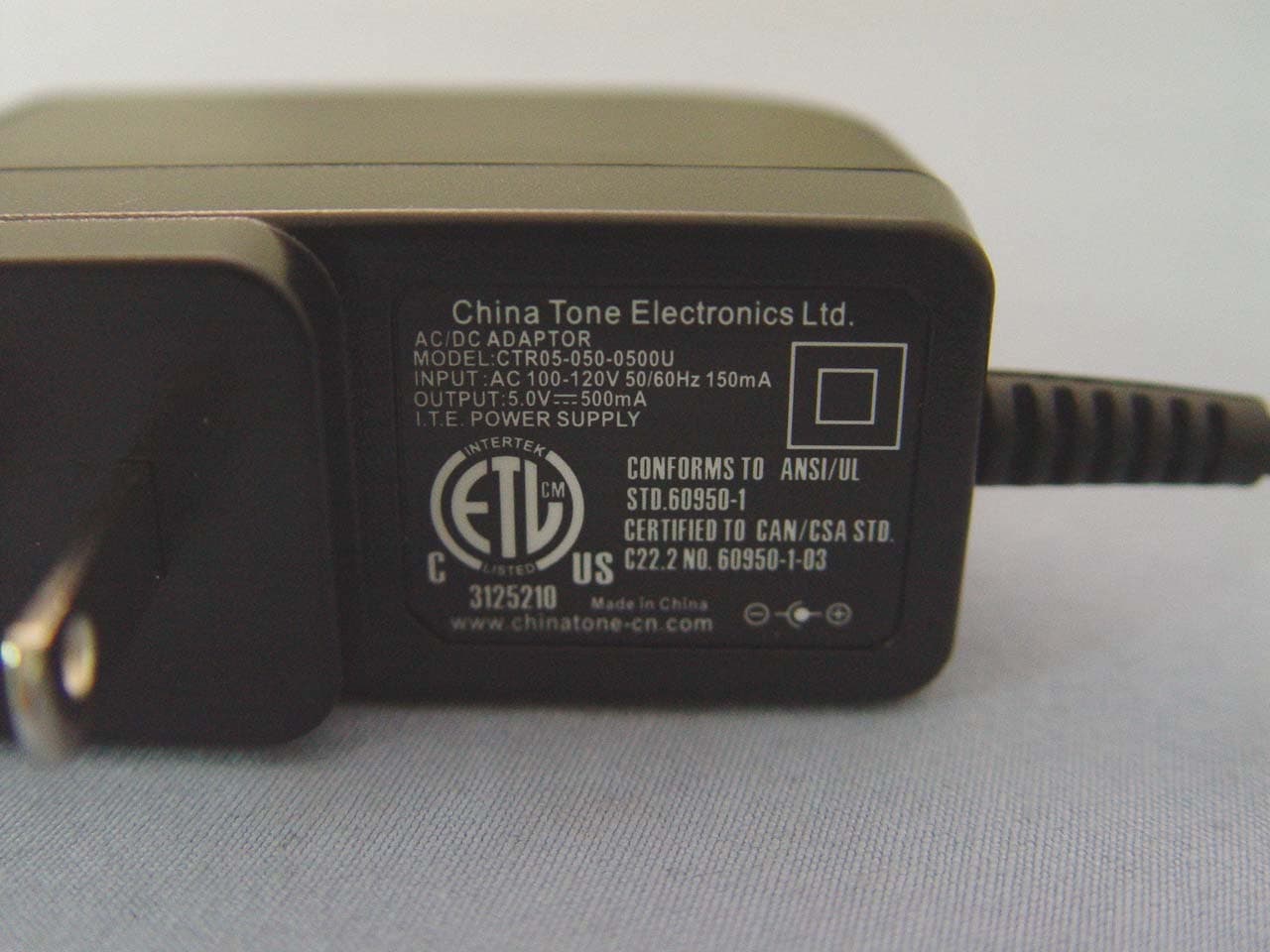
| 1 | 15C | 2.40 GHz - 2.48 GHz | 1.06 mW |
Other Applications from BT-Links Company Limited
TMY-BTM-118
Feb 02, 2008Bluetooth Headset
Equipment Class
DSS - Part 15 Spread Spectrum Transmitter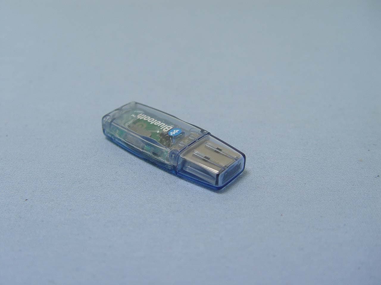
TMY-BT-30
Oct 24, 2007Dongle 2.0 EDR
Equipment Class
DSS - Part 15 Spread Spectrum Transmitter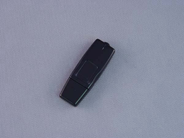
TMY-BT-20
Sep 08, 2005Bluetooth USB Dongle
Equipment Class
DSS - Part 15 Spread Spectrum Transmitter