TN8ODS4000VADigital Satellite Receiver
OPENTECH Inc.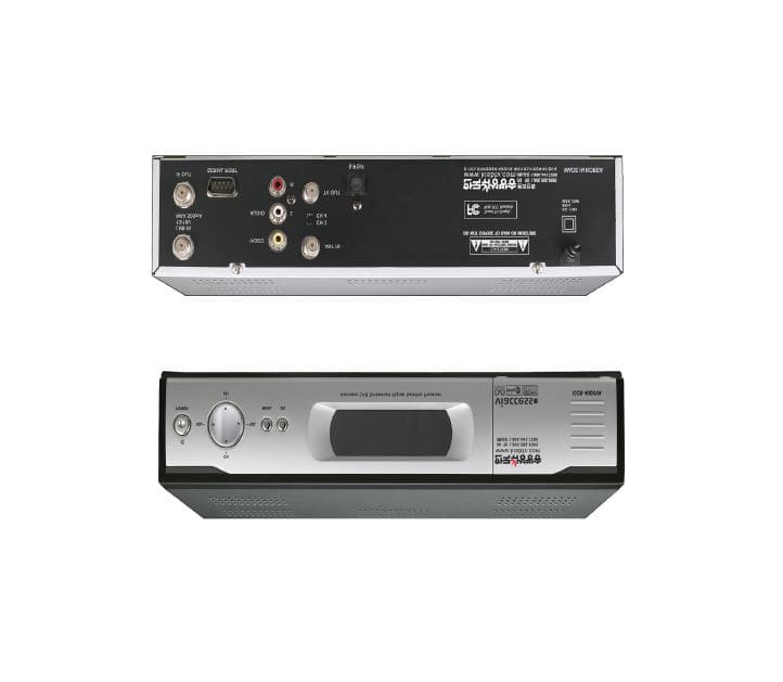
Click to zoom
Application Details
- Equipment Class
- HID - Part 15 TV Interface Device
- Date of Grant
- Sep 29, 2005
- Application Purpose
- Original Equipment
- Date of Application
- Sep 29, 2005
- Equipment Note
- Digital Satellite Receiver
- Frequency Range
- 67.25000000 - 71.25000000
- Company
- OPENTECH Inc.
- Country
- South Korea
Documents & Files
Document Text
Text extracted from the exhibit documents filed with the FCC. Open a document above to read the original.
Users Manual
User’s Manual Digital Satellite Receiver ODS 4000VA Viaccess CAS Embedded 1. SAFETY PRECAUTIONS 2. GENERAL FEATURES 3. HOW TO CONNECT YOUR RECEIVER 4. HARDWARE DESCRIPTION 5. SYSTEM SET-UP 6. MENU OPERATION 7. TROUBLE SHOOTING 8. TECHNICAL SPECIFICATIONS 2 3 4 6 10 11 20 21 Table of Contents Table of Contents Declaration of Conformity FCC Rule : TESTED TO COMPLY WITH FCC PART 15, CLASS B OPERATING ENVIRONMENT : FOR HOME OR OFFICE USE. FCC COMPLIANCE STATEMENT : This device complies with part 15 of the FCC rules. Operation is subject to the following conditions : 1) This device may not cause harmful interference, and 2) This device must accept any interference received, including interference that may cause undesired operation. INFORMATION TO USER: This equipment has tested and found to comply with the limits of a Class B digital device, pursuant to part 15 of the FCC Rules. These limit are designed to provide reasonable protection against harmful interference in a residential installation. This equipment generates, user and can radiate radio frequency energy and, if not installed and used in accordance with the instructions, may cause harmful interference to radio communications. However, there is no guarantee that interference will not occur in a particular installation, if this equipment does cause harmful interference to radio or television reception, which can be determined by turning the equipment off and on, the user is encouraged to try to correct the interference by one or more of the following measures: 1. Reorient / Relocate the receiving antenna. 2. Increase the separation between the equipment and receiver. 3. Connect the equipment into an outlet on a circuit difference from that to which the receiver is connected. 4. Consult the dealer or an experience radio / TV technician for help. CAUTION:Changes or modifications not expressly approved by manufacturer responsible for compliance could void the user's authority to operate the equipment. GENERAL FEATURES 3 SAFETY PRECAUTIONS 2 This receiver has been manufactured to satisfy the international safety standards. Please read the following recommended safety precautions carefully. MAINS SUPPLY: 95�240V AC 50/60Hz LOCATION: Locate the receiver indoor. Locate receiver away from potential hazards such as houseplants, lighting, raining and direct sunlight. OVERLOADING : Do not overload wall outlets, extension cords or adapters as this can result in fire or electrical shock. LIQUIDS: Keep liquids away from the receiver. CLEANING: Before cleaning, disconnect the receiver from the wall socket. Use a cloth lightly dampened with water (no solvents) to clean the exterior. VENTILATION: Do not block the receiver ventilation holes. Ensure that free airflow is maintained around the receiver. Never set the receiver on soft furnishings or carpets. Do not use or store the receiver where it is exposed to direct sunlight, or near heater. Never stack other electronic equipment on top of the receiver. Place the receiver at least 30mm from the wall. ATTACHMENTS: Do not use any attachment that is not recommended by the manufacturer, as it may cause a hazard or damage the equipment. CONNECTION TO THE SATELLITE DISH LNB: The LNB connector cable has a voltage in its center core. It is therefore recommended that the receiver is disconnected from the mains power before connecting or disconnecting this cable. FAILURE TO DO SO COULD DAMAGE THE LNB. SERVICING: Do not attempt to service this product yourself. Any attempt to do so will make the warranty invalid.Refer all servicing to a qualified service agent. LIGHTNING: If the receiver is installed in an area subject to intense lighting activity, protection devices for the receiver mains connector are essential. The individual manufacturer’s instruction for safeguarding other equipment, such as TV set, Hi-Fi, etc., connected to the receiver, must also be followed during lighting storms. GROUNDING: The ground of the LNB cable must be directly connected to the system ground for the satellite dish. The grounding system must comply with local regulations. 1. SAFETY PRECAUTIONS - Fully MPEG-2 & DVB Compliant - Smart Card Interface for Embeded Viaccess - Input Frequency 950�2150MHz - Supports SCPC & MCPC from C / Ku-band - 1 LNB Input Tuner with Loop Through IF Signal - Tuner Symbol Rate : 2�45MS/s - Fast Booting & Auto Scan - Quick Channel Changing - Max. 4000 Channels(TV & Radio) Programmable - User Friendly 256 Colors OSD & Easy GUI - A lot of OSD Language supported - Supports EPG, PIG - Radio Channel Background Display - Favorite Channel List Programmable - Master PIN Code Function & Parental Lock Function - 20 Steps Volume Control - Automatic Detection of Forward Error Correction - Automatic NTSC / PAL Detection and Simple Video Converter (NTSC <-> PAL) - S/W Upgrade by OTA - 4:3, 16:9 Letter Box & Teletext using OSD - 7 Segment-4 Digit Display - 5 Keys on the Front Panel (Power On/Off, Channel Up/Down, Volume Up/Down) - Various LNB Polarity Control - 3 RCA Output for Video, Audio L/R - NTSC RF Modulator (CH 3/4) - S/PDIF Output for Digital Audio 2. GENERAL FEATURES 0 HOW TO CONNECT YOUR RECEIVER 5 HOW TO CONNECT YOUR RECEIVER 4 Please DO NOT plug in the main power supply cord until you have finished all the connections. 1) LOCATION OF THE RECEIVER Your receiver should be placed under proper ventilation. Don’t put in completely enclosed cabinet that will restrict the flow of air, Resulting overheating. The location should be safeguarded from direct sunlight, excess moisture, rough handling or household pets. Avoid stacking other electronic components on the top of the receiver. The location should be safely accessible by the cable from your antenna system. 2) CONNECTING THE RECEIVER WITH DISH SYSTEM After installing your dish system, connect the coaxial cable from LNB of your dish antenna to “LNB IN”terminal marked at the rear of the receiver. All cable connectors should be finger tightened ; do not use any kind …
Text truncated - open the document above for the full version.
External Photos
Appendix C. External Photographs File No. E05.0927.FCC.600N, Page 1 of 1 Head Office : # 371-51 Kasan-Dong, Keumcheon-ku, Seoul, 153-803, Korea Tel : 82-2-858-0786 Fax : 82-2-858-0788 EMC Lab : #584 Sangwhal-ri, Kanam-myon, Yoju-kun, Kyounggi-do, 469-885, Korea Tel:82-31-885-0072, Fax:82-31-885-0074 ETL(E)004A4001201-0 Front side View of The EUT and Rear side View of The EUT
ID Label/Location Info
Appendix A. FCC ID Label and Location File No. E05.0927.600N, Page 1 of 2 Head Office : # 371-51 Kasan-Dong, Keumcheon-ku, Seoul, 153-803, Korea Tel : 82-2-858-0786 Fax : 82-2-858-0788 EMC Lab : #584 Sangwhal-ri, Kanam-myon, Yoju-kun, Kyounggi-do, 469-885, Korea Tel:82-31-885-0072, Fax:82-31-885-0074 ETL(E)004A4001201-0 Product Label Sample with FCC Label information Following is a sample copy of the label that will be placed on the rear cabinet of the product. The FCC ID Label and compliance statement are marked in the product label. OPENTECH INC. Digital Satellite Receiver FCC ID : TN8ODS4000VA Model No : ODS4000VA POWER : 110 Vac, 60 Hz, Max. 30W Serial No : N/A This device complies with part 15 of the FCC Rules. Operation is subject to the following two conditions: (1) This device may not cause harmful interference, and (2) This device must accept any interference received, including interference that may cause undesired operation Manufacturer : OPENTECH INC. Made in Korea Appendix A. FCC ID Label and Location File No. E05.0927.600N, Page 2 of 2 Head Office : # 371-51 Kasan-Dong, Keumcheon-ku, Seoul, 153-803, Korea Tel : 82-2-858-0786 Fax : 82-2-858-0788 EMC Lab : #584 Sangwhal-ri, Kanam-myon, Yoju-kun, Kyounggi-do, 469-885, Korea Tel:82-31-885-0072, Fax:82-31-885-0074 ETL(E)004A4001201-0 Label Location The label shown shall be permanently affixed at a conspicuous location on the device and be readily visible to the user at the time purchase.(Labeling requirements per 2.925) Label here
Internal Photos
Appendix D. Internal Photographs File No. E05.0927.FCC.600N, Page 1 of 11 Head Office : # 371-51 Kasan-Dong, Keumcheon-ku, Seoul, 153-803, Korea Tel : 82-2-858-0786 Fax : 82-2-858-0788 EMC Lab : #584 Sangwhal-ri, Kanam-myon, Yoju-kun, Kyounggi-do, 469-885, Korea Tel:82-31-885-0072, Fax:82-31-885-0074 ETL(E)004A4001201-0 Inside view of EUT Appendix D. Internal Photographs File No. E05.0927.FCC.600N, Page 2 of 11 Head Office : # 371-51 Kasan-Dong, Keumcheon-ku, Seoul, 153-803, Korea Tel : 82-2-858-0786 Fax : 82-2-858-0788 EMC Lab : #584 Sangwhal-ri, Kanam-myon, Yoju-kun, Kyounggi-do, 469-885, Korea Tel:82-31-885-0072, Fax:82-31-885-0074 ETL(E)004A4001201-0 Component side view of main board Appendix D. Internal Photographs File No. E05.0927.FCC.600N, Page 3 of 11 Head Office : # 371-51 Kasan-Dong, Keumcheon-ku, Seoul, 153-803, Korea Tel : 82-2-858-0786 Fax : 82-2-858-0788 EMC Lab : #584 Sangwhal-ri, Kanam-myon, Yoju-kun, Kyounggi-do, 469-885, Korea Tel:82-31-885-0072, Fax:82-31-885-0074 ETL(E)004A4001201-0 Solder side view of main board Appendix D. Internal Photographs File No. E05.0927.FCC.600N, Page 4 of 11 Head Office : # 371-51 Kasan-Dong, Keumcheon-ku, Seoul, 153-803, Korea Tel : 82-2-858-0786 Fax : 82-2-858-0788 EMC Lab : #584 Sangwhal-ri, Kanam-myon, Yoju-kun, Kyounggi-do, 469-885, Korea Tel:82-31-885-0072, Fax:82-31-885-0074 ETL(E)004A4001201-0 Component side view of power board Appendix D. Internal Photographs File No. E05.0927.FCC.600N, Page 5 of 11 Head Office : # 371-51 Kasan-Dong, Keumcheon-ku, Seoul, 153-803, Korea Tel : 82-2-858-0786 Fax : 82-2-858-0788 EMC Lab : #584 Sangwhal-ri, Kanam-myon, Yoju-kun, Kyounggi-do, 469-885, Korea Tel:82-31-885-0072, Fax:82-31-885-0074 ETL(E)004A4001201-0 Solder side view of power board Appendix D. Internal Photographs File No. E05.0927.FCC.600N, Page 6 of 11 Head Office : # 371-51 Kasan-Dong, Keumcheon-ku, Seoul, 153-803, Korea Tel : 82-2-858-0786 Fax : 82-2-858-0788 EMC Lab : #584 Sangwhal-ri, Kanam-myon, Yoju-kun, Kyounggi-do, 469-885, Korea Tel:82-31-885-0072, Fax:82-31-885-0074 ETL(E)004A4001201-0 Component side view of smart card board Appendix D. Internal Photographs File No. E05.0927.FCC.600N, Page 7 of 11 Head Office : # 371-51 Kasan-Dong, Keumcheon-ku, Seoul, 153-803, Korea Tel : 82-2-858-0786 Fax : 82-2-858-0788 EMC Lab : #584 Sangwhal-ri, Kanam-myon, Yoju-kun, Kyounggi-do, 469-885, Korea Tel:82-31-885-0072, Fax:82-31-885-0074 ETL(E)004A4001201-0 Solder side view of smart card board Appendix D. Internal Photographs File No. E05.0927.FCC.600N, Page 8 of 11 Head Office : # 371-51 Kasan-Dong, Keumcheon-ku, Seoul, 153-803, Korea Tel : 82-2-858-0786 Fax : 82-2-858-0788 EMC Lab : #584 Sangwhal-ri, Kanam-myon, Yoju-kun, Kyounggi-do, 469-885, Korea Tel:82-31-885-0072, Fax:82-31-885-0074 ETL(E)004A4001201-0 Component side view of front board Appendix D. Internal Photographs File No. E05.0927.FCC.600N, Page 9 of 11 Head Office : # 371-51 Kasan-Dong, Keumcheon-ku, Seoul, 153-803, Korea Tel : 82-2-858-0786 Fax : 82-2-858-0788 EMC Lab : #584 Sangwhal-ri, Kanam-myon, Yoju-kun, Kyounggi-do, 469-885, Korea Tel:82-31-885-0072, Fax:82-31-885-0074 ETL(E)004A4001201-0 Solder side view of front board Appendix D. Internal Photographs File No. E05.0927.FCC.600N, Page 10 of 11 Head Office : # 371-51 Kasan-Dong, Keumcheon-ku, Seoul, 153-803, Korea Tel : 82-2-858-0786 Fax : 82-2-858-0788 EMC Lab : #584 Sangwhal-ri, Kanam-myon, Yoju-kun, Kyounggi-do, 469-885, Korea Tel:82-31-885-0072, Fax:82-31-885-0074 ETL(E)004A4001201-0 View of RF modulator Appendix D. Internal Photographs File No. E05.0927.FCC.600N, Page 11 of 11 Head Office : # 371-51 Kasan-Dong, Keumcheon-ku, Seoul, 153-803, Korea Tel : 82-2-858-0786 Fax : 82-2-858-0788 EMC Lab : #584 Sangwhal-ri, Kanam-myon, Yoju-kun, Kyounggi-do, 469-885, Korea Tel:82-31-885-0072, Fax:82-31-885-0074 ETL(E)004A4001201-0 View of satellite tuner
Operational Description
2004/01/25 1 RF Modulator NTSC-M TAMC-H410F LG Innotek Rev.A Preliminary specification 2004/01/25 2 RF Modulator NTSC-M TAMC-H410F LG Innotek Rev.A Preliminary specification 1. INTORDUCTION 1.1 Features Systems : NTSC-M (3.58MHz) US 3/4 Channel True 5V device (Low power dissipation) Software Control for channel 3/4 1.2 Revision History Revision DESCRIPTION A Initial Release 2. DESCRIPTION The TAMC-H410F type are available with 75ohm input for loop through mode and 75ohm out . All connectors is available in standard F-type connectors. TheTAMC-H410F consists of a modulator section and loop-through section, which are all designed on a single PCB. Channel selecting is done with terminal No.2. 2.1 Pin Description SYMBOL PIN DESCRIPTION A-IN 1 Audio signal in (Input impedance : Higher than 350) CH 2 Channel Select HIGH for 3Ch. // LOW for 4Ch. MB 3 Modulator B+ CTL 4 Control HIGH for Normal Mode LOW for P/Save Mode V-IN 5 Video signal in (Input impedance : 1) 2.2 Limiting Values Limiting values under operational conditions The modulator can be guaranteed to function properly under the following conditions. SYMBOL PARAMETER PIN MIN. TYP. MAX. UNIT A-IN Input Impedance 1 350 MB Modulator B+ 4.8 5.0 5.2 V I(MB) Modulator B+ supply current 3 60 70 mA CTL Control 0.3 5.2 V I(CTL) Control supply current 4 8 15 mA V-IN Input Impedance 5 0.85 1.0 1.15 B [Ripple] Allowable Ripple Voltage 3, 4 10 mVp-p Note : For detailed information about the address decoding, refer to chapter application information. 2004/01/25 3 RF Modulator NTSC-M TAMC-H410F LG Innotek Rev.A Preliminary specification 2.3 Environmental Conditions SYMBOL PARAMETER CONDITIONS MIN. TYP. MAX. UNIT Non-operational conditions Tamb Ambient temperature 10 +70 RH Relative humidity 90 % Operational conditions Tamb Ambient temperature 0 +60 RH Relative humidity 85 % 2.4 Overall Performance Conditional data Unless otherwise specified, all electrical values for Chapter overall performance apply at the following conditions. SYMBOL PARAMETER VALUE UNIT Tamb Ambient temperature 255 RH Relative humidity 6015 % MB Supply voltage 50.125 V Zi Aerial source impedance (unbalanced) 75 3 ELECTRICAL CHARACTERISTICS Test Condition : Temperature: 253 // Relative humidity : 45~65% ( unless otherwise specified ) 3.1 RF Out Characteristics Parameter Min. Typ. Max. Unit Note RF Output Level 63 66 69 Peak value level at standard Modulation. RF Frequency 90 90 kHz Measure the difference from the desired frequency P/S Ratio 13 16 19 Measure the level difference Between video and audio. Out-band Spurious 30 Measure the level difference against the Video at standard modulation. Measure range : 0~1GHz Except the range fP~fP+fS In-band Spurious 70 60 Measure between fv and fs (against fv level.) Chroma Beat 70 58 Based on standard-modulated fv (against fv level ) Video signal: SC 3.58 0.4Vp-p 2004/01/25 4 RF Modulator NTSC-M TAMC-H410F LG Innotek Rev.A Preliminary specification 3.2 Video Characteristics Parameter Min. Typ. Max. Unit Note Input Signal Condition 1.0 Vp-p of negative sync. 82 loaded Video Modulation 75 80 85 % Input level : 1.0Vp-p White Clip 100 % Input level : 1.5Vp-p Video S/N 50 dB Measure at the out of the standard Demodulator, video measurement set. H.P.F : 100, L.P.F : 4.5 SC Trap : ON, weighted Video : 100% White signal Audio : non-modulation DG 5 2 5 % Input signal 10 stair step case DP 5 2 5 deg Input signal 10 stair step case 1.5 0.5 1.5 dB 0.5~4.1MHz Video Frequency Characteristics 6.0 0.5 1.5 dB 4.1~4.2MHz Based on 1. Apply sweep signal or multi-burst signal into video input terminal 3.3 Audio Characteristics Parameter Min. Typ. Max. Unit Note Input Signal Level 1.23 Vp-p Sine wave @ 1kHz Audio Modulation 64 80 96 % 100% = 25 Dev. Audio S/N 50 Standard modulation. Video Signal : Color bar 1Vp-p Measured by HP8903B(Equivalent) LP Filter : ON De-emphasis : ON Audio Distortion 1.0 % Standard Modulation De-emphasis (75usec) : ON Audio Frequency Characteristics 2.0 0 1.5 0.1kHz~10kHz, Based 1kHz, De-emphasis : ON Audio Gain 2.25 3.0 3.75 Measured by HP8903B(Equivalent) Audio Carrier Frequency 7 0 7 kHz The measurement is taken after 30 sec. from the power on. 2004/01/25 5 RF Modulator NTSC-M TAMC-H410F LG Innotek Rev.A Preliminary specification 3.4 Loop-through Section Characteristics Parameter Min. Typ. Max. Unit Note Insertion Loss 4 dB In=> Out, 54MHz ~ 806MHz 3 In, 54MHz ~ 806MHz (MD : Off) 3 Out, 54MHz ~ 806MHz (MD : Off) VSWR 3 Out, 60MHz~72MHz (MD : ON) Isolation 60 dB In => Out, 60MHz ~ 72MHz (MD : ON) Voltage Leakage Aerial In terminal 9.5 75 terminate. Unused terminal shall be terminated at 75. f 1 f 2 f IM Input Level Inter-modulation (In => Out) 183 189 177 100 50 dB Min. Inter-modulation 183 189 195 100 50 dB Min. 3.5 Thermal Stabilities Parameter Min. Typ. Max. Unit Note RF Output Level 3 3 dB RF Frequency 100 100 kHz Audio Carrier Frequency 20 20 KHz P/S Ratio 3 3 dB Video Modulation 10 10 % Sync Level 0.5 0.5 DG 12 12 DP 12 12 deg Audio Modulation 10 10 % Measure the difference of initial value and deviated value according to the temperature measurement order from 0to 60 2004/01/25 6 RF Modulator NTSC-M TAMC-H410F LG Innotek Rev.A Preliminary specification 4. MECHANICAL CHARACTERISTICS Parameter Standard Value Measurement Method Process Normal condition applies. Visual inspection Stain or Damage Neither stain nor damage shall be permitted. Visual inspection Electrical contact Neither stain nor damage shall be permitted. Visual inspection Weight 60g maximum Typ. 50g Total Pullout Force for Coaxial Connector Initial: between 1kg and 5kg After 100 times, 0.8 kg minimum Connector Neither bend nor play shall be permitted. 5. OTHER TESTS 5.1 Vibration Test The rated performance shall be satisfied. The unit is set to the fixture and then vibrated with total amplitude of 2 mm, Frequency range 7 Hz to 30 Hz, once per minute consecutively for 10 minutes in each of three axes (X,Y,Z). 5.2 Tapping Test The rated performance shall be satisfied. T…
Text truncated - open the document above for the full version.
Test Report
www.etl.re.kr E-RAE Testing Laboratory This report only responds to the tested sample and may not be reproduced, except in full, without written approval of the ETL,Inc. Electromagnetic Emission FCC MEASUREMENT REPORT CERTIFICATION OF COMPLIANCE FCC Part 15 Certification Measurement This Digital Satellite Receiver, Model ODS4000VA has been tested in accordance with the measurement procedures specified in ANSI C63.4-2001 at the ETL/EMC Test Laboratory and has been shown to complied with the electromagnetic radiated emission limits specified in FCC Rule Part 15 Subpart B: TV interface device. I attest to the accuracy of data. All measurement here in was performed by me or was made under my supervision and is correct to the best of my knowledge and belief. I assume full responsibility for the completeness of these measurements and vouch for the qualifications of all persons taking them. The results of testing in this report apply to the product/system, which was tested only. Other similar equipment will not necessarily produce the same results due to production tolerance and measurement uncertainties. Hyung Seok, Lee / Chief Engineer ETL Inc. #584 Sangwhal-ri, Kanam-myon, Yoju-kun, Kyounggi-do, 469-885, Korea PRODUCT : Digital Satellite Receiver MODEL/TYPE NO : ODS4000VA FCC ID : TN8ODS4000VP APPLICANT / ADDRESS : OPENTECH INC. 13F.,SJ-Technoville 60-19,Gasan-Dong,Geumcheon-Gu, Seoul, Korea Attn.:Jong-Sam Park / Senior Research Engineer MANUFACTURER OPENTECH INC. ADDRESS 13F.,SJ-Technoville 60-19,Gasan-Dong,Geumcheon-Gu, Seoul, Korea FCC CLASSIFICATION : HID : TV interface device FCC RULE PART(S) : FCC Part 15 Subpart B FCC PROCEDURE : Certification TRADE NAME : KISB TEST REPORT No. : E05.0927.FCC.600N DATES OF TEST : September 06 - 27, 2005 DATES OF ISSUE : September 27, 2005 TEST LABORATORY : ETL Inc. (FCC Registration Number: 95422) #584 Sangwhal-ri, Kanam-myon, Yoju-kun, Kyounggi-do, 469-885, Korea Tel: 82-31- 885-0072 Fax: 82-31-885-0074 FCC TEST REPORT File No. E05.0927.FCC.600N, Page of 21 Head Office : # 371-51 Kasan-Dong, Keumcheon-ku, Seoul, 153-803, Korea Tel : 82-2-858-0786 Fax : 82-2-858-0788 EMC Lab : #584 Sangwhal-ri, Kanam-myon, Yoju-kun, Kyounggi-do, 469-885, Korea Tel:82-31-885-0072, Fax:82-31-885-0074 ETL(E)004A4001201-0 Table of Contents FCC Measurement Report 1. Introduction 2. Product Information 3. Description of Tests 4. Test Condition 5. Test Results 5.1 Summary of Test Results 5.2 Conducted Emission Test 5.3 Radiated Emission Test 5.4 Antenna Power Conduction Meaurement 5.5 Output Signal Level Measurement 5.6 Output Terminal Conducted Spurious Emission Measurement 5.7 Transfer Switch Measurement 6. Sample Calculation 7. List of test Equipment used for Measurements Appendix A. FCC ID Label and Location Appendix B. Test Setup Photographs Appendix C. External Photographs Appendix D. Internal Photographs Appendix E. Block Diagram Appendix F. Operating Manual FCC TEST REPORT File No. E05.0927.FCC.600N, Page 3 of 22 Head Office : # 371-51 Kasan-Dong, Keumcheon-ku, Seoul, 153-803, Korea Tel : 82-2-858-0786 Fax : 82-2-858-0788 EMC Lab : #584 Sangwhal-ri, Kanam-myon, Yoju-kun, Kyounggi-do, 469-885, Korea Tel:82-31-885-0072, Fax:82-31-885-0074 ETL(E)004A4001201-0 FCC MEASUREMENT REPORT Scope – Measurement and determination of electromagnetic emission(EME) of radio frequency devices including intentional radiators and/or unintentional radiators for compliance with the technical rules and regulations of the U.S Federal Communications Commission(FCC) General Information l Model Number : DSR-600 l FCC Identifier : TN8ODS4000VA l S/N : N/A l Freq. Range : 61.25MHz – 71.75MHz l FCC Rule Part(s) : Part 15 Subpart B l Test Procedure : ANSI C63.4-2001 l FCC Classification : TV Interface Device l RF Channels : Ch. 3 / Ch. 4 l Dates of Tests : September 06 - 27, 2005 l Place of Tests : ETL Inc. 584, Sangwhal-Ri, Kanam-Myun, Yoju-Kun, Kyounggi-Do, Korea Tel : 82-31- 885-0072 Fax : 82-31- 885-0074 l Test Report No. : E05.0927.FCC.600N Applicant Name : OPENTECH INC. Address : 13F., SJ-Technoville 60-19, Gasan-Dong, Geumcheon-Gu, Seoul, Korea, 153-801 Manufacturer : OPENTECH INC. Address : 13F., SJ-Technoville 60-19, Gasan-Dong, Geumcheon-Gu, Seoul, Korea, 153-801 Attention : Jong-Sam Park / Senior Research Engineer FCC TEST REPORT File No. E05.0927.FCC.600N, Page 4 of 22 Head Office : # 371-51 Kasan-Dong, Keumcheon-ku, Seoul, 153-803, Korea Tel : 82-2-858-0786 Fax : 82-2-858-0788 EMC Lab : #584 Sangwhal-ri, Kanam-myon, Yoju-kun, Kyounggi-do, 469-885, Korea Tel:82-31-885-0072, Fax:82-31-885-0074 ETL(E)004A4001201-0 The measurement test for radiated and conducted emission test were conducted at the shielded anechoic chamber room and open area test site of E-RAE Testing Laboratory Inc. facility located at 584, Sangwhal-ri, Ganam-myun, Youju-kun, Kyoungki-do, Korea. The site is constructed in conformance with the requirements of the ANSI C63.4-2001 and CISPR Publication 16. The ETL has site descriptions on file with the FCC for 3 and 10 meter site configurations. Detailed description of test facility was found to be in compliance with the requirements of Section 2.948 FCC Rules according to the ANSI C63.4-2001 and registered to the Federal Communications Commission(Registration Number : 95422 ). The measurement procedure described in American National Standard for Method of Measurement of Radio-Noise Emission from Low-Voltage Electrical and Electronic Equipment in the Range of 9kHz to 40GHz (ANSI C.63.4-2001) was used in determining radiated and conducted emissions from the OPENTECH INC. Digital Satellite Receiver, Model : ODS4000VA FCC TEST REPORT File No. E05.0927.FCC.600N, Page 5 of 22 Head Office : # 371-51 Kasan-Dong, Keumcheon-ku, Seoul, 153-803, Korea Tel : 82-2-858-0786 Fax : 82-2-858-0788 EMC Lab : #584 Sangwhal-ri, Kanam-myon, Yoju-kun, Kyounggi-do, 469-885, Korea Tel:82-31-885-0072, Fax:82-31-885-0074 ETL(E)004A4001201-0 2.1 Equipment Description The Equipment Under Test(EUT) is th…
Text truncated - open the document above for the full version.
Test Setup Photos
Appendix B. Test Setup Photographs File No. E05.0927.FCC.600N, Page 1 of 4 Head Office : # 371-51 Kasan-Dong, Keumcheon-ku, Seoul, 153-803, Korea Tel : 82-2-858-0786 Fax : 82-2-858-0788 EMC Lab : #584 Sangwhal-ri, Kanam-myon, Yoju-kun, Kyounggi-do, 469-885, Korea Tel:82-31-885-0072, Fax:82-31-885-0074 ETL(E)004A4001201-0 Radiated Emission Test Setup Appendix B. Test Setup Photographs File No. E05.0927.FCC.600N, Page 2 of 4 Head Office : # 371-51 Kasan-Dong, Keumcheon-ku, Seoul, 153-803, Korea Tel : 82-2-858-0786 Fax : 82-2-858-0788 EMC Lab : #584 Sangwhal-ri, Kanam-myon, Yoju-kun, Kyounggi-do, 469-885, Korea Tel:82-31-885-0072, Fax:82-31-885-0074 ETL(E)004A4001201-0 Conducted Emission Test Setup Appendix B. Test Setup Photographs File No. E05.0927.FCC.600N, Page 3 of 4 Head Office : # 371-51 Kasan-Dong, Keumcheon-ku, Seoul, 153-803, Korea Tel : 82-2-858-0786 Fax : 82-2-858-0788 EMC Lab : #584 Sangwhal-ri, Kanam-myon, Yoju-kun, Kyounggi-do, 469-885, Korea Tel:82-31-885-0072, Fax:82-31-885-0074 ETL(E)004A4001201-0 Antenna Power Conduction Measurement Test Setup Output Signal Level Measurement Test Setup Appendix B. Test Setup Photographs File No. E05.0927.FCC.600N, Page 4 of 4 Head Office : # 371-51 Kasan-Dong, Keumcheon-ku, Seoul, 153-803, Korea Tel : 82-2-858-0786 Fax : 82-2-858-0788 EMC Lab : #584 Sangwhal-ri, Kanam-myon, Yoju-kun, Kyounggi-do, 469-885, Korea Tel:82-31-885-0072, Fax:82-31-885-0074 ETL(E)004A4001201-0 Output Terminal Conducted Spurious Emission Measurement Test Setup Antenna Transfer Switch Measurement
Contact Information
Applicant
Jae Sung Kim(Project Manager)
Test Firm
E-RAE Testing LaboratoryYo Han Park
Technical Specifications
| # | Rule Parts | Frequency Range | Power Output |
|---|---|---|---|
| 2 | 15B | 67.25 MHz - 71.25 MHz | - |
Other Applications from OPENTECH Inc.

TN8-OWC-401T
Aug 22, 2013Wireless Charger
Equipment Class
DCD - Part 15 Low Power Transmitter Below 1705 kHz
TN8-OWC-300T
Feb 06, 2013Wireless Charging Pad
Equipment Class
DCD - Part 15 Low Power Transmitter Below 1705 kHz