TPD2G352Fingerprint and Card Reader
ID3 Semiconductors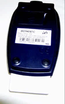
Click to zoom
Application Details
- Equipment Class
- JBP - Part 15 Class B Computing Device Peripheral
- Date of Grant
- Dec 06, 2005
- Application Purpose
- Original Equipment
- Date of Application
- Dec 06, 2005
- Equipment Note
- Fingerprint and Card Reader
- Company
- ID3 Semiconductors
- Country
- France
Documents & Files
Document Text
Text extracted from the exhibit documents filed with the FCC. Open a document above to read the original.
Users Manual
ELECTRONIC MICRO ELECTRONIC INNOVATIVE PRODUCTS Understand - Analyse – Design - Evolve Créé le 07/10/2005 11:04 XSPC5K1420.doc Page 1/1 id3 Semiconductors - 5, rue de la Verrerie - F 38120 Le Fontanil Cornillon – RCS Grenoble B 377 846 951 – APE 321C - SAS au capital de 200.000€ Tel : +33 (0)4 76 75 75 85 - Fax : +33 (0)4 76 75 52 30 – WEB:http://www.id3semiconductors.com - Email : [email protected] Thank you for purchasing Biothentic. Manufacturer: id3 Semiconductors www.id3semiconductors.com Kit reference: 082G352A This kit includes : 1 Biothentic smart card reader 1 Biothentic USB dedicated cable 1 Biothentic Software Application CD ROM Security Instruction The Biothentic was designed to be plugged to USB 1.0 or 2.0 host products only. Installation Follow CD ROM instruction before connecting the biothentic reader. Cable: The provided cable is compliant with USB specifications. This was designed and qualified to work with biothentic and to meet European and US reglementations. You shouldn’t use any other cable type. SAM installation / replacement: (Specific Application Module) The SAM operations are reserved to security officers . In order to install or remove a SAM : 1 : Disconnect the Usb cable 2 : Download ESD by touching the biothentic USB plug with your finger. 3 : Open the SAM plastic door 4 : unlock the SAM holder 5 : insert / remove the SAM 6 : close and lock the SAM holder 7 : close the plastic door. Warning Any changes or modifications not expressly approved by the party responsible for compliance could void the user’s authority to operate the equipment Repairs Repairs should only be performed by qualified technicians only. During warranty period, the product should be returned to id3 semiconductors official distributor for repair purpose. Warranty voids if the product is not properly used or if installation instructions are not respected. Waste of Electric & Electronic Equipments : As an Electronic Equipment, Biothentic should not be thrown into a waste container ! European Directive 2002/96/EC Orders to have EEE recycled. In order to have this product recycled, please contact your Biothentic distributor. Keep these safety instructions EC DECLARATION OF CONFORMITY We id3 Semiconductors 5 rue de la Verrerie F-38120 Le Fontanil Cornillon FRANCE Declare under sole responsability that the 08G352A Biothentic fingerprint and smart card reader meets the intent of the European directives. Compliance was demonstrated to the following specifications as listed in the Official Journal of the European Communities: EMC Directive 89/336/EEC EN55022 Class B (1998) IEC 61000-4-2 - 1996+A1(1998)+A2(2001) IEC 61000-4-3 - 1996+A1(1998)+A2(2001) Security Directive 73/23/EEC IEC60950-1:2001 FCC COMPLIANCE This equipment has been tested and found to comply with the limits for a Class B digital device, pursuant to part 15 of the FCC Rules. These limits are designed to provide reasonable protection against harmful interference in a residential installation. This equipment generates, uses and can radiate radio frequency energy and, if not installed and used in accordance with the instruction, may cause harmful interference to radio communications. However, there is no guarantee that interference will not occur in a particular installation. If this equipment does cause harmful interference to radio or television reception which can be determined by turning the equipment off and on, the user is encouraged to try to correct interference by one or more of the following measures: - Reorient or relocate the receiving antenna. - Increase the separation between the equipment and receiver. - Connect the equipment into an outlet on circuit different from that to which the receiver is connected. - Consult the dealer or an experienced radio/TV technician for help. Jean-Louis Revol CEO
Block Diagram
FCC ID: , TPD2G352 1 BLOCK DIAGRAM OF EQUIPMENT 1.1 Clock list of Biothentic product Crystal oscillator: 6 MHz, 10MHz,, 20MHz Data rate: - PLL 5MHz, 12MHz, 33MHz - No clock or signal higher than 108 MHz FCC ID: , TPD2G352 1.2 Block diagram of Biothentic product
External Photos
FCC ID: TPD2G352 Page 1/1 EXTERNAL PHOTOS OF TESTED EUT 1.1 BIOthentic General view Lower face FCC ID: TPD2G352 Page 2/2 Front face, without smart card Rear face
ID Label/Location Info
FCC ID: TPD2G352 1 PRODUCT LABELING 1.1 FCC ID label This is a photo of the label stuck on the product. Size: 51x25mm Color: Black on silver Material: Polyester Label 1.2 Location of the label on EUT FCC information are set on the rear face of the product (see picture). label will be stuck at that location FCC ID: TPD2G352 1.2.1 User's manuel Just below, is a copy of the FCC statement set inside the user's manual
Internal Photos
FCC ID: TPD2G352 Page 1 / 3 1 INTERNAL PHOTOS OF TESTED EUT 1.1 Biothentic Cover removed (fingerprint reader side) SAM cover removed (rear face) rear face without cover FCC ID: TPD2G352 Page 2 / 3 smart card reader side (rear side) Smart card reader fence removed front side FCC ID: TPD2G352 Page 3 / 3 1.2 Fingerprint reader fingerprint reader removed front side rear side
Operational Description
FCC ID: TPD2G352 1 GENERAL INFORMATION 1.1 Product description The Biothentic device is smart card reader combined with a fingerprint reader. When authentication is requested, the card bearer is invited to sweep his “main” finger on the Biothentic reader. The reader sent the scanned result inside the card for authentication process. The embedded authentication algorithm compares the received data with the one stored inside the card. If they match, the card grants the rights of all applications for which it was designed and secured transactions can operate. Application: - E-commerce, - Immigration card - Citizen card - Access card to sensitive site - Bank card - Voter card - Jail access card - E-signature of documents... The Biothentic is a product developed by the ID3 Semiconductors Company. For more information, see product's data sheet at section 1.6. 1.2 Related Submittal(s) / Grant(s) All host equipment used in the test configuration are FCC granted, when relevant. 1.3 Tested System Details The FCC IDs for all equipment, plus description of all cables used in the tested system (including inserted cards, which have grants) are : See test report file : 3511-FCC 1.4 Test Methodology Both conducted and radiated testing was performed according to the procedures in ANSI C63.4-2000, CISPR22-2003 and EN55022:1998+/A1:2000+/A2:2003. Radiated testing was performed at an antenna to EUT distance of 10 meters. During testing, all equipment’s and cables were moved relative to each other in order to identify the worst case set-up. 1.5 Test facility Tests have been performed on September 19 th , 2005. The test facility used to collect the radiated and conducted data is the LCIE (Etablissement Voiron) facility, located ZI des Blanchisseries, 38500 VOIRON, France. This test facility has been fully described in a report and accepted by FCC as compliant with the radiated and AC line conducted test site criteria in ANSI C63.4-1992 in a letter dated July 14, 2005 (registration number 94821). This test facility has also been accredited by COFRAC (French accreditation authority for European Union test lab accreditation organization) according to NF EN ISO/IEC 17025, accreditation number 1-1633 as compliant with test site criteria and competence in 47 CFR Part 15/ANSI C63.4 and EN55022/CISPR22 norms for 89/336/EEC European EMC Directive application. All pertinent data for this test facility remains unchanged. FCC ID: TPD2G352 1.6 Data sheet of the product
Test Report
Etablissement de Voiron Z.I. des Blanchisseries 38500 Voiron Siret 408 363 174 00090 Tél. : +33 4 76 65 09 08 Fax : +33 4 76 66 18 30 [email protected] LCIE 33, av du Général Leclerc Tél : +33 1 40 95 60 60 Société Anonyme Laboratoire Central BP 8 Fax : +33 1 40 95 86 56 au capital de 15 745 984 € Des Industries Electriques 92266 Fontenay-aux-Roses cedex [email protected] RCS Nanterre B 408 363 174 Une société de Bureau Veritas France www.lcie.fr This test report applies only on equipment described hereafter. Proposal number : 200509-2761 Date of test...................................: October 3 rd , 2005 Location........................................: LCIE Laboratory - 38500 VOIRON - France Performed by.................................: Jacques LORQUIN Customer.......................................: ID3 Semiconductors 5 rue de la verrerie 38120 Le Fontanil Cornillon FRANCE Product..........................................: BIOTHENTIC Type of test...................................: Radiated and Conducted Emission Test Applied standards or specification: EN55022 (1999) +/A1: (2000) +/A1: (2003) CISPR22 (2003) FCC part 15 subpart B Level.............................................: Class B Test objective................................: Qualification Results..........................................: Samples tested in configuration and description presented in this test report complies with prescriptions and limits of EN 55022, CISPR22 and FCC part 15 subpart B standard, in radiated and conducted emissions. The reproduction of this test report is authorized only under its entire form. This report contents 10 pages Written by.........................: Jacques LORQUIN Approved by.....................: Jacques LORQUIN Date: October 10 th ,2005 EMC TEST REPORT Nr 3511-FCC Nr 3511-FCC October 3rd, 2005 page 2 /10 1. System test configuration 1.1. Justification The system was configured for testing in a typical fashion (as a customer would normally use it). The soft test read SAM and smart card, and fingerprint in loop. 1.2. HARDWARE IDENTIFICATION: ÿ Equipment Under Test (EUT): Biothentic pn:08G352A 1 Sn : 00921411. ÿ Size : 84x133x40mm ÿ I/O : - 1X USB connector ÿ Frequencies : Crystal: 6MHz, 10MHZ, 20MHz 1.3. Running mode: For testing Biothentic, the software Xlog2M001 V1.10 running in loop under Windows XP pro. Test Commands: - SCardConnect (shared, T=0) - ScardBegin Transaction - Blink - SAM PowerOn - SAM Negociate - SAM Exchange (GetChallenge) - SAM Power Off - Blink - ScardTransmit (T=0, getchallenge) - GetImage (Normal/4BPP) - Waitfor response (1000) - Display image (Normale/4BPP) - Blink - Scard End Transaction (leave_card) - Scard Disconnect (leave_card) Nr 3511-FCC October 3rd, 2005 page 3 /10 1.4. Auxiliaries The FCC IDs for all equipment, plus description of all cables used in the tested system (including inserted cards, which have grants) are : Trade Mark – Model Number (Serial number) FCC ID Description Cable description ID3 pn:08G352A 1* (sn: 00921411) TPD2G352 Smart card and fingerprint reader USB cable, shielded HEWLETT PACKARD pn:PE199ET#ABF (sn: HUB43809JS) D.O.C. Personnel computer I/O Shielded cable Standard power cable unshielded Compaq pn:235212-102INTL (sn: 1zr62ecf2af) CMYKPQ6987 Keyboard PS/2 Shielded cable Compaq pn: 334684-108 (sn:5187-1786) JNZ211443 Mouse PS/2 Shielded cable PHILIPS pn: 17B6822N (sn: TY009717020677) none Monitor Shielded cable with ferrite at the end. * : Equipment under test 1.5. I/O cables - 2x Power cord (PC & Monitor), unshielded, length: 2m - 1x USB cable with ferrite at each end, shielded, length: 2m 1.6. Equipment modifications No modifications are necessary for achieved test. 2. Radiated emission data from 30MHz to 1GHz 2.1. SET-UP Mains: 230V@50Hz The equipment under test and auxiliaries are set on a non-conducted table of 80cm height, above the ground plane. The distance between equipement under test and auxiliaries is 10cm. Nr 3511-FCC October 3rd, 2005 page 4 /10 2.2. TEST EQUIPMENT Test Equipment from 30MHz to 1GHz on 10 meters open site: The installation of EUT is identical for pre-characterization measures in a 3 meters full anechoic chamber and for measures on a 10 meters Open site. Test Equipment from 30MHz to 1GHz on 10 meters open site: Equipment Company Model Serial Spectrum Analyzer HP 8568B 2732A04140 Quasi-Peak adapter HP 85650A 2811A01136 RF Pre-selector HP 85685A 2833A00773 Biconical Antenna EMCO 3104C 9401-4636 Log Periodic Antenna EMCO 3146 2178 Absorbing clamp LÜTHI MDS21 194.0100.50 Absorbing clamp LÜTHI MDS21 2826 EMCO-1050, 6 meters height antenna mast & EMCO-1060, 3 meters diameter Turntable. A 10 meters Open site located in LCIE - Voiron (FRANCE). Nr 3511-FCC October 3rd, 2005 page 5 /10 Pre-scan, test Equipment from 30MHz to 1GHz: Equipment Company Model Serial EMC Analyzer HP 8591EM 3536A00384 Amplifier HP 8447F H64 3113A06394 Antenna (30MHz-1GHz) CHASE CBL6111A 1628 Absorbing clamp LÜTHI MDS21 194.0100.50 Absorbing clamp LÜTHI MDS21 2826 2.3. TEST SEQUENCE AND RESULTS 2.3.1. Pre-characterization at 3 meters A pre-scan of all the setup has been performed in a 3 meters full anechoic chamber. The distance between EUT and antenna is 3 meters. Test is performed in horizontal (H) and vertical (V) polarization, and on 4 faces of the EUT. See below for graph examples. Nr 3511-FCC October 3rd, 2005 page 6 /10 2.3.2. Characterization on 10 meters open site from 30MHz to 1GHz The product has been tested according to ANSI C63.4-(2003), CISPR22-2003 and EN55022:1998/A1:2000/A1:2003. Radiated Emission was measured on an open area test site. A description of the facility is on file with the FCC. Interconnecting cables and equipment's were moved to position that maximized emission. A summary of the worst case emissions found in all test configurations and modes is shown on clause 2.1. Frequency list has been created with anechoic chamber pre-scan results. No Frequency (MHz) QPeak Lmt (dBμV/m) QPeak (dBμV/m) QPeak-Lmt (dB) …
Text truncated - open the document above for the full version.
Test Setup Photos
FCC ID: MESGMP 1 CONDUCTED AND RADIATED MEASUREMENT PHOTOS 1.1 Radiated emissions setup from 30MHz to 1GHz Front view Rear view FCC ID: MESGMP 1.2 Conducted emission setup
Contact Information
Applicant
Jean-Louis REVOL(CEO)
Test Firm
LCIE Sud-EstJacques Lorquin
Technical Specifications
| # | Rule Parts | Frequency Range | Power Output |
|---|---|---|---|
| 1 | 15B | - | - |
Other Applications from ID3 Semiconductors
TPD7P217
Jun 12, 2007USB Fingerprint Reader
Equipment Class
JBP - Part 15 Class B Computing Device Peripheral
TPD5K048
Mar 08, 2006RFID Tag Reader
Equipment Class
DXX - Part 15 Low Power Communication Device Transmitter
TPD2H190
Dec 01, 2005Fingerprint Reader
Equipment Class
JBP - Part 15 Class B Computing Device Peripheral