TPD2H190Fingerprint Reader
ID3 Semiconductors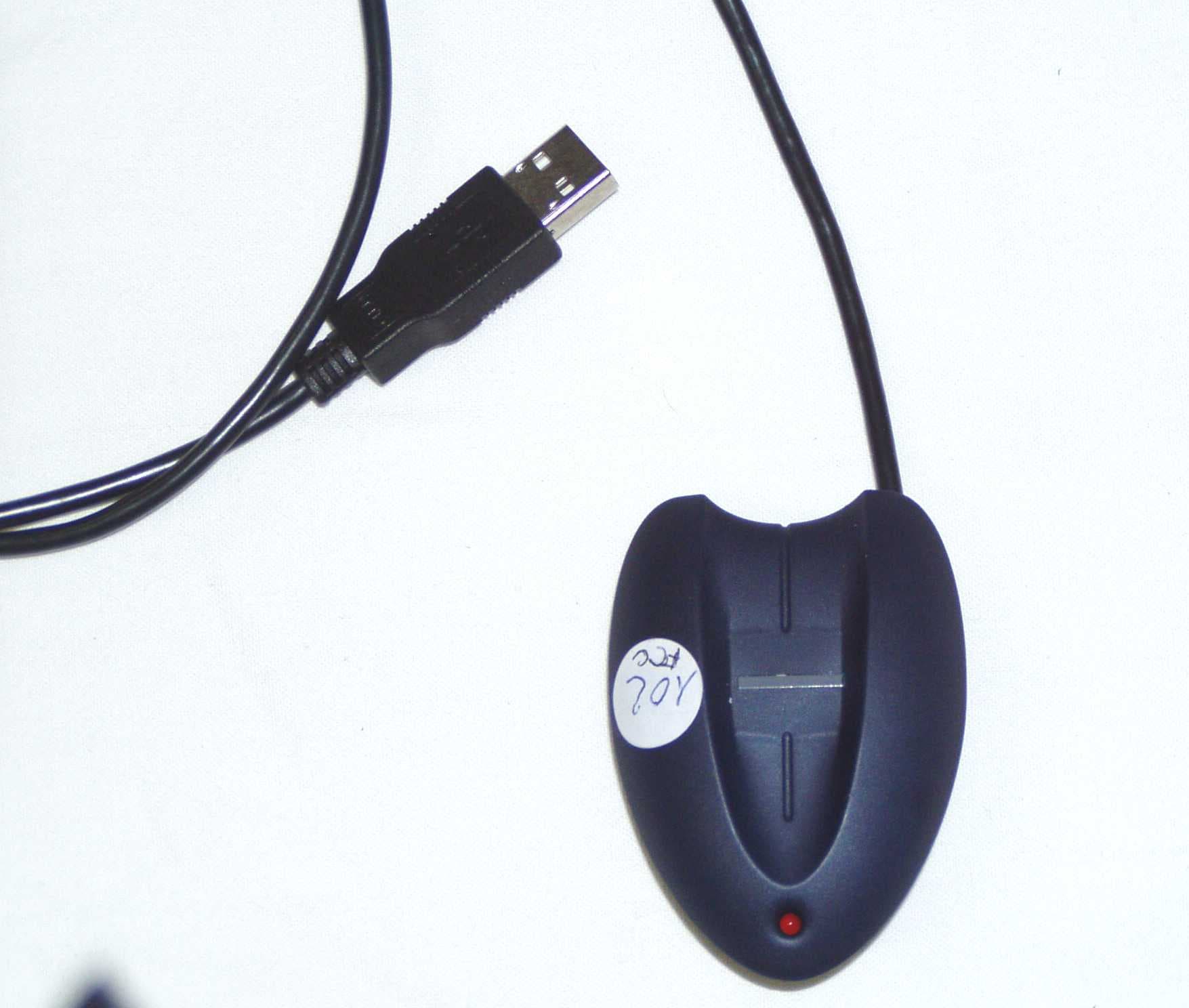
Click to zoom
Application Details
- Equipment Class
- JBP - Part 15 Class B Computing Device Peripheral
- Date of Grant
- Dec 01, 2005
- Application Purpose
- Original Equipment
- Date of Application
- Dec 01, 2005
- Equipment Note
- Fingerprint Reader
- Company
- ID3 Semiconductors
- Country
- France
Documents & Files
Document Text
Text extracted from the exhibit documents filed with the FCC. Open a document above to read the original.
Block Diagram
FCC ID: TPD2H19Ø Page 1/1 1BLOCK DIAGRAM OF EQUIPMENT 1.1Clock list of the CERTISproduct - 12MHz - 2MHz - 100kHz 1.2Block diagram of the CERTISproduct
External Photos
FCC ID: TPD2H19Ø Page 1/2 EXTERNAL PHOTOS OF TESTED EUT CERTIS external photos General view, upperface General view, rear face FCC ID: TPD2H19Ø Page 2/2 Detail view, left and right sides
ID Label/Location Info
FCC ID: TPD2H19Ø Page 1/1 1PRODUCT LABELING 1.1FCC ID label This is a copy of the label : Label material : Polyester (printed by thermal transfer) 1.2Location of the label on EUT Thelabel is set on the rear side of the equipment. Label location (rear side)
Internal Photos
FCC ID: TPD2H190 Page 1/3 INTERNAL PHOTOS OF TESTED EUT 1.1General view General view, cover opened (upper side) General view, PCB removed (upper side) FCC ID: TPD2H190 Page 2/3 General view, plastic covers (upper and lower side) General view, lower side. FCC ID: TPD2H190 Page 3/3 1.2PCB view
Operational Description
FCC ID: TPD2H190 Page1/2 OPERATIONAL DESCRIPTION 1.1.Product description of the CERTIS product FCC ID: TPD2H190 Page2/2 1.2.Related Submittal(s) / Grant(s) All host equipment used in the test configuration are FCC granted, when relevant. 1.3.Tested System Details The FCC IDs for all equipment, plus description of all cables used in the tested system are: Trade Mark – Model Number (Serial number) FCC IDDescriptionCable description CERTIS * Sn: 01040029 USB biometric reader USB cable, shielded (1m attached to the equipment) PC IBM 300PL Model: 6562-340 sn : 55784X1 DOCPersonal computerAC mains cable, 1.8m unshielded SVGA standard cable, 1.5m Keyboard IBM KB-7953 KeyboardPS2 cable Monitor HP D2817-60014 DOCMonitorAC mains cable,1.8m unshielded SVGA cable Mouse TREKKER MousePS2 cable * : Equipment under test 1.4.Test Methodology Radiated testing was performed according to the procedures in ANSI C63.4-2003, FCC Part 15 Subpart B. Radiated testing was performed at an antenna to EUT distance of 10 meters. Radiated testing was performed at an antenna to EUT distance of 10 meters. During testing, all equipment’s and cables were moved relative to each other in order to identify the worst case set-up. 1.5.Test facility Tests have been performed on October 3 rd , 2005. The test facility used to collect all the test data is the LCIEfacility, located ZI des Blanchisseries, 38500 VOIRON, France. This test facility has been fully described in a report and accepted by FCC as compliant with the radiated and AC line conducted test site criteria in ANSI C63.4-2003in a letter dated July 14, 2005 (registration number 94821). This test facility has also been accredited by COFRAC (French accreditation authority for European union test lab accreditation organization) according to NF EN ISO/IEC 17025, accreditation number 1-1633as compliant with test site criteria and competence in 47 CFR Part 15/ANSI C63.4 and EN55022/CISPR22 norms for 89/336/EEC European EMC Directive application. All pertinent data for this test facility remains unchanged.
Test Report
This test report applies only on equipment described hereafter. Proposal number:200509-2762 Date of test...................................: October 3rd, 2005 Location........................................: LCIE ZI des Blanchisseries 38500 VOIRON - FRANCE Performed by................................: Laurent CHAPUS Customer......................................: ID3 5 rue de la verrerie 38000 Le Fontanil Le Cornillon FRANCE Product.........................................: CERTIS(FCC ID: TPD2H19Ø) Type of test.................................. : Radiated and Conducted Emission Test Applied standards or specification:EN55022 (1999) + A1 (2000)+ A2 (2003) CISPR22 (1997) + A1 (2000)+ A2 (2002) ANSI C63-4 (2003) Level............................................: CISPR 22 Class B Test objective...............................: Qualification Results.........................................: Samples tested in configuration and description presented in this test report complies with prescriptions and limits of EN 55022 and CISPR 22 standards (class B), in radiated and conducted emissions. The reproduction of this test report is authorized only under its entire form. This report contents 9 pages. Written by.........................: Date : December 1 st , 2005 Laurent CHAPUSApproved by....................: Jean-Pierre ORY EMC TEST REPORT Nr 3544-FCC FCC ID: TPD2H190 Nr3544-FCCOctober3rd,2005page 2 /9 1. System test configuration 1.1. JUSTIFICATION: The system was configured for testing in a typical fashion (as a customer would normally use it). The biometric reader CERTIS is connected to a PC, through the USB link. 1.2. HARDWARE IDENTIFICATION: * Equipment Under Test (EUT):CERTISSn: 01040029 FCC ID: TPD2H19Ø Input/output : - 1x USB port (cable 1m, shielded) Frequencies : - 12MHz, 2MHz, 100kHz 1.3. AUXILIARIES: The FCC IDs for all equipment, plus description of all cables used in the tested system are: Trade Mark – Model Number (Serial number) FCC IDDescriptionCable description CERTIS * Sn: 01040029 TPD2H19ØUSB biometric reader USB cable, shielded (1m attached to the equipment) PC IBM 300PL Model: 6562-340 sn : 55784X1 DOCPersonal computer AC mains cable, 1.8m unshielded SVGA standard cable, 1.5m Keyboard IBM KB-7953 KeyboardPS2 cable Monitor HP D2817-60014 DOCMonitorAC mains cable,1.8m unshielded SVGA cable Mouse TREKKER MousePS2 cable * : Equipment under test 1.4. Running mode: The biometric reader is connected to the USB port of a PC. The software used during the test permits the acquisition of fingerprints, read on the tested CERTIS sensor. Tests are performed while the readeris waiting for an acquisition. 1.5. I/O CABLES: - 2x Power cords, unshielded:1.5m(PC and monitor) - 1x SVGA standard cable, shielded, with ferrite at each end: 1.5m - 1x USB cable, shielded, attached to the CERTIS reader : 1m 1.6. EQUIPMENT MODIFICATIONS: No equipment modification has been necessary during testing to achieve compliance to class B levels. The unit tested was representative to a production unit. FCC ID: TPD2H190 Nr3544-FCCOctober3rd,2005page 3 /9 2. Radiated emission data 2.1. TEST SET-UP: Mains: 230V/50Hz The equipment under testand auxiliariesareset on a non-conducted table of 80cm height, above the ground plane. Radiated test setup The installation of EUT is identical for pre-characterization measures in a 3 meters full anechoic chamber and for measures on a 10 meters Open site. 2.2. TEST EQUIPMENT: Test Equipment from 30MHz to 1GHz on 10 meters open site: EquipmentCompany ModelSerial Spectrum AnalyzerHP8568B 2732A04140 Quasi-Peak adapterHP85650A2811A01136 RF Pre-selectorHP85685A2833A00773 Biconical AntennaEMCO3104C9401-4636 Log Periodic AntennaEMCO31462178 Absorbing clampLÜTHIMDS212826 Absorbing clampR&S85024A194.0100.50 OATS EMCO-1050, 6 meters height antenna mast & EMCO-1060, 3 meters diameter Turntable. A 10 meters Open site located in LCIE- Voiron (FRANCE). Pre-scan, test Equipment from 30MHz to 1GHz: EquipmentCompany ModelSerial EMC Analyzer HP8591EM3536A00384 AmplifierHP8447F H643113A06394 Antenna (30MHz-1GHz)CHASECBL6111A1628 Absorbing clampLÜTHIMDS212826 Absorbing clampR&S85024A194.0100.50 FCC ID: TPD2H190 Nr3544-FCCOctober3rd,2005page 4 /9 2.3. TEST SEQUENCE AND RESULTS: 2.3.1.Pre-characterization at 3 meters A pre-scan of all the setup has been performed in a 3 meters full anechoic chamber. The distance between EUT and antenna is 3 meters. Test is performed in horizontal (H) and vertical (V) polarization, and on 4 faces of the EUT. See below for graphs examples. Graphs are obtained using a PEAK detector. 30MHz-1GHz radiated emissions (Horizontal polarization) MarkerFreq.PeakComments [MHz][dBuV] 1 59.9827.78 2 192.531.83 3 731.534.08 FCC ID: TPD2H190 Nr3544-FCCOctober3rd,2005page 5 /9 30MHz-1GHz radiated emissions (Vertical polarization) MarkerFreq.PeakComments [MHz][dBuV] 1 35.7326.44 2 192.524.21 3 200.026.95 4 664.937.90 5 997.435.70 2.3.2.Characterization on 10 meters open site from 30MHz to 1GHz The product has beentested according to ANSI C63.4(2003), CISPR22- 1997/A1:2000/A2:2002and EN55022:1998/A1:2000/A2:2003. Radiated emissions were measured on an open area test site. A description of the facility is on file with the FCC. The product has been tested with 230V/50Hz power line voltage, at a distance of 10 meters from the antenna and compared to the CISPR 22 Class B limits. Measurement bandwidth was 120kHz from 30MHz to 1GHz. Antenna height search was performed from 1m to 4m for both horizontal and vertical polarization. Continuous linear turntable azimuth search was performed with 360 degrees range. Interconnecting cables and equipmentswere moved to position that maximized emission. A summary of the worst case emissions found in all test configurations and modes is shown on clause 2.3.1. Frequency list has been created with anechoic chamber pre-scan results. FCC ID: TPD2H190 Nr3544-FCCOctober3rd,2005page 6 /9 2.3.3.Qualification results Frequency list has been created with anechoic c…
Text truncated - open the document above for the full version.
Test Setup Photos
FCC ID: TPD2H19Ø Page 1/2 MEASUREMENT PHOTO 1.1Radiated emissions (10m open site) EUT 80cm above the ground reference plane Detail view FCC ID: TPD2H19Ø Page 2/2 1.2Conducted emissions Conducted emissions test setup Detail view
Contact Information
Applicant
Jean-Louis REVOL(CEO)
Test Firm
LCIE Sud-EstJacques Lorquin
Technical Specifications
| # | Rule Parts | Frequency Range | Power Output |
|---|---|---|---|
| 1 | 15B | - | - |
Other Applications from ID3 Semiconductors
TPD7P217
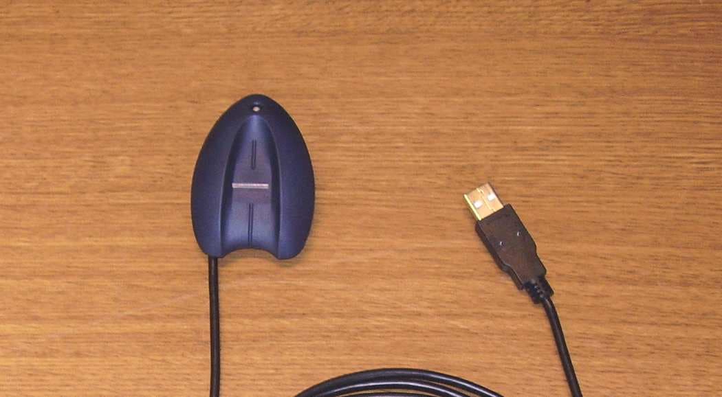
Jun 12, 2007USB Fingerprint Reader
Equipment Class
JBP - Part 15 Class B Computing Device Peripheral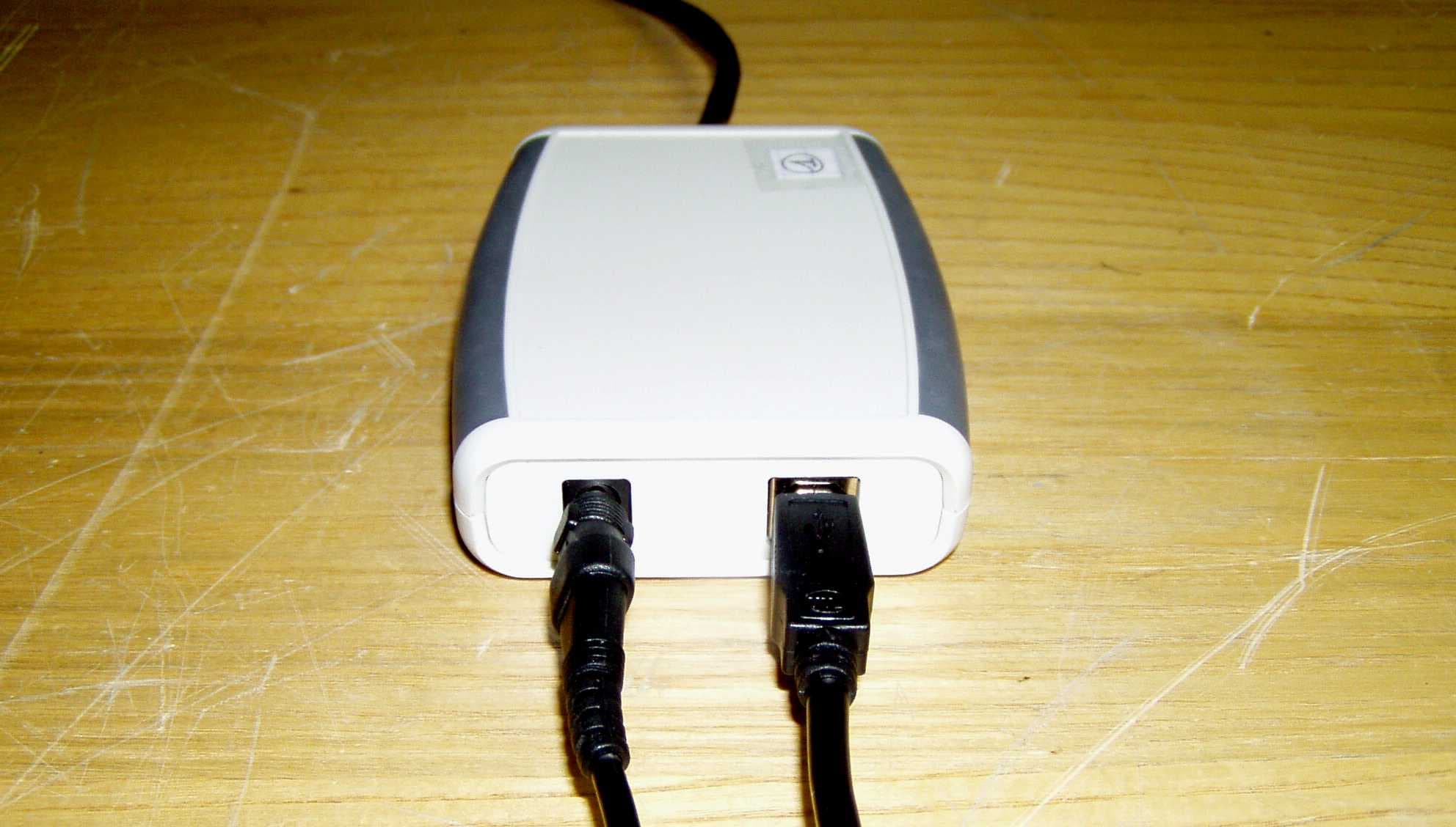
TPD5K048
Mar 08, 2006RFID Tag Reader
Equipment Class
DXX - Part 15 Low Power Communication Device Transmitter
TPD2G352
Dec 06, 2005Fingerprint and Card Reader
Equipment Class
JBP - Part 15 Class B Computing Device Peripheral