TPZ-34000001-001IntelliPad
Vue Technology, Inc.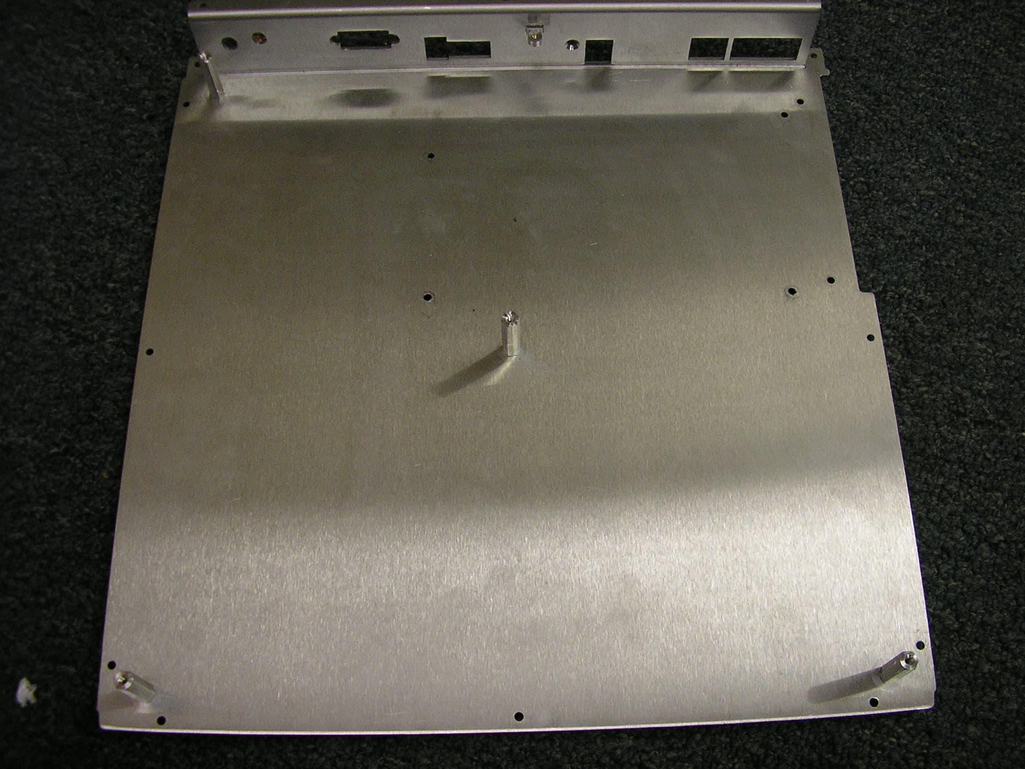
Click to zoom
Application Details
- Equipment Class
- DSS - Part 15 Spread Spectrum Transmitter
- Date of Grant
- Feb 01, 2006
- Application Purpose
- Original Equipment
- Date of Application
- Feb 01, 2006
- Equipment Note
- IntelliPad
- Frequency Range
- 902.75000000 - 927.25000000
- Company
- Vue Technology, Inc.
- Country
- United States
Documents & Files
Document Text
Text extracted from the exhibit documents filed with the FCC. Open a document above to read the original.
Users Manual
IntelliPad User Guide Document Version: 1.1 Last Modified: 1/24/2006 6:39:00 PM Vue Technology, Inc. 103 N. Pointe Lake Forest, CA 92630 www.vuetechnology.com Vue Technology, Inc. IntelliPad User Guide Date Last Modified: 1/24/2006 Page 2 Vue Technology, Inc. Table of Contents 1. INTRODUCTION ...................................................................................................................................................... 3 2. PRODUCT DESCRIPTION...................................................................................................................................... 3 3. FIRMWARE ............................................................................................................................................................... 3 4. PHYSICAL CONNECTIONS ................................................................................................................................... 3 5. TYPICAL CONFIGURATION................................................................................................................................. 6 6. REGULATORY INFORMATION ........................................................................................................................... 7 Vue Technology, Inc. IntelliPad User Guide Date Last Modified: 1/24/2006 Page 3 Vue Technology, Inc. 1. Introduction This User Guide provides information for the Vue Technology IntelliPad device. The User Guide includes LED definitions, port descriptions, and configuration information. 2. Product Description The Vue Technology IntelliPad is a hardware device that connects to a RF reader, the Vue Technology ItemTrack Server, and a hand-held barcode scanner. The device allows the user to read and/or write EPC and barcode information to and from RFID tags that are placed on the IntelliPad or scanned via the barcode scanner. 3. Firmware The IntelliPad is shipped with the current firmware version. Contact Vue Technology (www.vuetechnology.com) for information about obtaining firmware upgrades. Note: Ensure that power is not interrupted during a firmware upgrade. 4. Physical Connections The IntelliPad hardware form factor consists of a circuit board, microprocessor, RF antenna, and moulded plastic housing. External indicators include: • Status lights – 3 large top-mounted LEDs (Red, Green, and Yellow). • Audible buzzer embedded in the top panel. • 3 small side-mounted LEDs (Green, Green, and Green). 4.1.1.1. Back Panel Descriptionf External connections: • 10/100 Mbit Ethernet port for connection to IntelliManager. • 10/100 Mbit Ethernet port to daisy chain to next IntelliPad. • 10/100 Mbit Ethernet port for (opt) LCD monitor or third party product. • 85 QMA 50-0-3 PCB Jack (HF RF in connector). The HF port is not supported in the current version of this product. Do not connect any device to the HF port. • 1.0/2.3 R/A PCB Jack (UHF RF in connector). • DB-9 connector, for RS-232 scanner input. Note: Uses only TX, RX, CTS, RTS pins. • 2.5 mm ID, 5 mm OD, 9-24 VDC power input jack, + center pin. • 2.5 mm ID, 5 mm OD, 9-24 VDC power output jack, + center pin input power to this IntelliPad, output power to optional next IntelliPad in daisy-chain. • Power On/Off switch. When off, this IntelliPad will power down, but power will still be supplied to 24 VDC power output jack. Vue Technology, Inc. IntelliPad User Guide Date Last Modified: 1/24/2006 Page 4 Vue Technology, Inc. UHF HF IntelliPad Back Panel 4.1.1.2. Side Panel Description External connections: • 2.5 mm ID, 5 mm OD, 5-24 VDC power input jack, + center pin. • 2.5 mm ID, 5 mm OD, 5-24 VDC power output jack, + center pin. Input is from specific reader power supply, output is to the reader itself. • RJ-45 (future use for third party products or debug port). • DB-9, RS-232 connection for reader, also used for diagnostics debug output data. • 3 green LEDs IntelliPad Side Panel Vue Technology, Inc. IntelliPad User Guide Date Last Modified: 1/24/2006 Page 5 Vue Technology, Inc. Vue Technology, Inc. IntelliPad User Guide Date Last Modified: 1/24/2006 Page 6 Vue Technology, Inc. 5. Typical Configuration CAUTION: Use only Vue Technology provided parts, or parts approved/recommended by Vue Technology. Substituting other cables or parts may degrade system performance, damage the device, and/or void the warranty. Vue Technology, Inc. IntelliPad User Guide Date Last Modified: 1/24/2006 Page 7 Vue Technology, Inc. 6. Regulatory Information The following statements address FCC compliance for the installation and use of Vue Technology devices. • The Vue Technology system is approved to function with the following tag reader: Symbol XR400 multi-protocol radio frequency identification (RFID) reader. FCCID: H9PRD11320 • IMPORTANT: The HF port is not supported in the current version of this product. Do not connect any device to the HF port. • CAUTION: To comply with FCC RF exposure compliance requirements, a separation distance of 20cm must be maintained between the antenna of this device and all persons. • CAUTION: The reader power settings for the IntelliPad cannot exceed +27.5 dBm. The acceptable power range is limited to a maximum of +27.5 dBm to comply with FCC regulations. This equipment has been tested and found to comply with the limits for a class B digital device, pursuant to part 15 of the FCC Rules. These limits are designed to provide reasonable protection against harmful interference in a residential installation. This equipment generates, uses, and can radiate radio frequency energy and if not installed and used in accordance with the instructions, may cause harmful interference to radio communications. However, there is no guarantee that interference will not occur in a particular installation. If this equipment does cause harmful interference to radio or television reception, which can be determined by turning the equipment off and on, the user is encouraged to try to correct the interference by one or more of the following …
Text truncated - open the document above for the full version.
Cover Letter(s)
Scott McCutchan From: Scott McCutchan [[email protected]] Sent: Wednesday, December 07, 2005 4:06 PM To: '[email protected]' Subject: FCC ID: TPZ-34000001-001 12/7/2005 Mr. Madlangbayan: In order for processing of this application (FCC ID: TPZ-34000001-001) to continue, the following issue(s) will have to be addressed: 1) The operational description indicates that the tag reader output power was set at 25 dBm, yet the test report indicates that the peak power level was 27.8 dBm (worst-case, on center channel). Please explain this discrepancy. 2) The operational description also indicates that the length of the cable connecting the internal patch antenna of the IntelliPad to the circuit board, as well as the length of the cable which connects the IntelliPad to the tag reader, may be changed according to the installation needs. a. Please explain how the output power is controlled under these circumstances. b. Indicate how the installation is controlled, such as the type of cabling that is used, correct setting of power levels, etc. 3) The operational description states that the user is able to adjust the power settings. a. Please indicate how this is accomplished. b. Please explain in detail the method by which the power is controlled. c. If it is adjusted incrementally, what are the increments by which it may be adjusted. d. What is the lowest power level? 4) The operational description indicates that the “user is able to adjust the power setting to any antenna from zero to that power setting”. The original certification of the tag reader (FCC ID: H9PRD11320) indicates that 14.74 dBm is the lowest power level. a. Does the “zero” value indicated correspond to 0 dBm? b. If so, how is this level achieved considering the output of the reader is only adjustable down to 14.74 dBm? 5) The test setup photos, and internal photos show a piece of copper tape from the chassis to the RF connectors. Please explain why this was present. 6) On the internal photos of the device, there is a white sticker covering some of the electronics. Please submit photos of the circuitry covered by this sticker. 7) A signed TCB contract must be on file in order for the review process to be completed. The item(s) indicated above must be submitted before processing can continue on the above referenced application. Failure to provide the requested information within 60 days of the original e-mail date may result in application dismissal and forfeiture of the filing fee. Also, please note that partial responses increase processing time and should not be submitted. Please upload responses and/or exhibits to the electronic filing website. Your correspondence number is TPZ-34000001-001. Best regards, Scott McCutchan Operations Manager Compatible Electronics TCB 114 Olinda Drive Brea, CA 92823 (714) 579-0500 Fax (714) 579-1850 If you have any questions, feel free to contact me. Best regards, Scott McCutchan Lab Manager Compatible Electronics Silverado / Lake Forest Division (949) 589-0700 fax (949) 589-7700 [email protected] 12/7/2005
Cover Letter(s)
Correspondence by Project Project Number: -786105241 Correspondence Number Memo MR. McCUTCHAN, 1) The operational description indicates that the tag reader output power was set at 25 dBm, yet the test report indicates that the peak power level was 27.8 dBm (worst-case, on center channel). Please explain this discrepancy. >>>>Please see the revised operational description documentation in the exhibits uploaded. 2) The operational description also indicates that the length of the cable connecting the internal patch antenna of the IntelliPad to the circuit board, as well as the length of the cable which connects the IntelliPad to the tag reader, may be changed according to the installation needs. a. Please explain how the output power is controlled under these circumstances. b. Indicate how the installation is controlled, such as the type of cabling that is used, correct setting of power levels, etc. >>>>a. The measurements were taken with the shortest len gth cable provided. The system controlling software does not allow the Reader to be set to a level higher than +25 dBm when connected to an IntelliPad. b. Longer cables introduce greater losses than those tested. This will reduce the power available at the IntelliPad input port. The user can only control the power of the reader throu gh the system software that limits the value to +25 dBm. 3) The operational description states that the user is able to adjust the power settings. a. Please indicate how this is accomplished. b. Please explain in detail the method by which the power is controlled. c. If it is adjusted incrementally, what are the increments TPZ-34000001-001 by which it may be adjusted. d. What is the lowest power level? >>>>a. Page four of the operational description "IntelliPad - Description of Circuit Function.pdf" states: "The user is able to adjust the power setting to any antenna from zero to that power setting." This is not correct. It should state: "The system is configured during installation to provide any power level from the minimum available Reader power level up to +25 dBm." b. A software program controls the setting of the power to the reader. The user enters a value on the keyboard and the software insures that the value does not exceed +25 dBm. When it is time to turn the reader on, the software uses the value entered on the keyboard. c. Power may be adjusted in increments provided by the Reader which is in 0.5 dB steps. d. The lowest power level is that level provided by the Reader is 14.74 dBm. 4) The operational description indicates that the “user is able to adjust the power setting to any antenna from zero to that power setting”. The ori ginal certification of the tag reader (FCC ID: H9PRD11320) indicates that 14.74 dBm is the lowest power level. a. Does the “zero” value indicated correspond to 0 dBm? b. If so, how is this level achieved considering the output of the reader is only adjustable down to 14.74 dBm? >>>>>a) This was mistake in the manual since we thought the Reader could go to 0 dBm. We will change the manual to state that the minimum is "the minimum provided by the Reader". b) It can not reach 0 dBm. 5) The test setup photos, and internal photos show a piece of copper tape from the chassis to the RF connectors. Please explain why this was present. >>>>>The copper tape simulated the chassis mounting nut for that connector. We didn't have the nut available at the time. 6) On the internal photos of the device, there is a white sticker covering some of the electronics. Please submit photos of the circuitry covered by this sticker. >>>>>Photos of the PCB with sticker removed are in the exhibits uploaded.
ID Label/Location Info
PWRANT RDY RS 485 SWITCHED POWER ID OUTIN Side Panel Serial Port #1 Back Panel LAN 1LAN 3LAN 2 AUX RESET PARAM POWER BUS Local Area Network Reset Factory Settings RS 232 Serial Port #2 UHF HF RS 232 IntelliPad ™ INPUT: 24V 5A RF INPUTS Device ID Notification Power and Diagnostics Antenna Ready FCC ID: TPZ-34000001-001 This device complies with part 15 of the FCC rules. Operation is subject to the following two conditions: (1) this device may not cause harmful interference. (2) it must accept any interference received including interference that may cause undesired operation. E256092 I.T.E. SERIAL NUMBER: 02051910000A MAC ADDRESS: 02051910000A Made in the U.S.A. Patent Pending Model Number: 34000001-001-RA MAC ADDRESS: 02051910000A 2.500 .500 2.750 3.750 R .06 CUTOUT #1 .020 DEEP CUTOUT #2 .020 DEEP CUTOUT #3 .020 DEEP 1.900 .625 R .03 R .03
ID Label/Location Info
ABCD ABCD 2 1 2 1 A A 12.10 11.98 TOLERANCES FRACTIONS:±1/64 ANGLES: ±0°30' ENGLISH: METRIC: .XX ±.01 .X ±0.1 .XXX ±.005 .XX ±0.05 DO NOT SCALE PRINT GEOMETRIC SYMBOLS CONCENTRICITY TRUE POSITION PERPENDICULARITY PARALLELISM ANGULARIY FLATNESS REV 3.0 DRAWING NO. D SCALE 1.000 SHEET 1 OF 1 FINISH CLEAR ANODIZE DESCRIPTION: INTELLIPAD CHASSIS PLATE PART NUMBER: 91000510-001 MATERIAL 5052 ALUMINUM APPR.BYDESIGNER: MWV HERBST LAZAR BELL INC. 26812 VISTA TERRACE LAKE FOREST, CA 92630 949.586.5875 Fax:949.586.5891 DR: HLB CAD MODEL: 91000519-001REV20_CHAS_PLT DATE: 4-05-05 JOB NO. REVISIONS REVDESCRIPTIONDATE DRAWN BY APPR. BY 2.0HOLE LOCATION CHANGES4-22-05HLBTC 3.0HOLE LOCATION CHANGES4-25-05HLBTC NOTES: 1 INSTALL PENN ENGINEERING PART NO. SOS-6440-12 OR EQUIV 4 PLACES MARKED "A" A A A A 1 2.500 .500 R.03 CUTOUT #3 .020 DEEP This device complies with part 15 of the FCC rules. Operation is subject to the following two conditions: (1) this device may not cause harmful interference. (2) it must accept any interference received including interference that may cause undesired operation.
RF Exposure Info
MAXIMUM PERMISSIBLE EXPOSURE MEASUREMENTS ANTENNA GAIN (dBi) Distance at which MPE exceeds FCC limit for Occupational/Controlled Exposure (3 mW/cm2) Distance at which MPE exceeds FCC limit fo r General Population/General Exposure (0.6 mW/cm2) intellipad27.84.10.3016.314.1 intelliSwitch26.84.10.2445.712.7 intelliRoute r27.74.10.3016.314.1 EUT POWER OUTPUT (dBm) CALCULATED MPE 20cm (mW/cm2)
Test Report
Report Number: C50728J2 FCC Part 15 Subpart B and FCC Section 15.247 Test Report Brea Division 114 Olinda Drive Brea, CA 92823 (714) 579-0500 Agoura Division 2337 Troutdale Drive Agoura, CA 91301 (818) 597-0600 Silverado Division 19121 El Toro Road Silverado, CA 92676 (949) 589-0700 Lake Forest Division 20621 Pascal Way Lake Forest, CA 92630 (949) 587-0400 Page 1 of 24 FCC PART 15, SUBPART B and C TEST REPORT for INTELLIPAD MODEL: 34000001-001-RA FCC ID: TPZ-34000001-001 Prepared for VUE TECHNOLOGY, INC. 95 ENTERPRISE SUITE 320 ALISO VIEJO, CALIFORNIA 92656 Prepared by:_________________________ JOEY MADLANGBAYAN Approved by:________________________ JOHN ETHINGTON COMPATIBLE ELECTRONICS INC. 19121 EL TORO ROAD SILVERADO (LAKE FOREST), CALIFORNIA 92676 (949) 589-0700 DATE: OCTOBER 30, 2005 REPORT APPENDICES TOTAL BODY A B C D E PAGES 24 2 2 2 13 46 89 This report shall not be reproduced except in full, without the written approval of Compatible Electronics. Report Number: C50728J2 FCC Part 15 Subpart B and FCC Section 15.247 Test Report Brea Division 114 Olinda Drive Brea, CA 92823 (714) 579-0500 Agoura Division 2337 Troutdale Drive Agoura, CA 91301 (818) 597-0600 Silverado Division 19121 El Toro Road Silverado, CA 92676 (949) 589-0700 Lake Forest Division 20621 Pascal Way Lake Forest, CA 92630 (949) 587-0400 Page 2 of 24 TABLE OF CONTENTS Section / Title PAGE GENERAL REPORT SUMMARY 4 SUMMARY OF TEST RESULTS 5 1. PURPOSE 6 2. ADMINISTRATIVE DATA 7 2.1 Location of Testing 7 2.2 Traceability Statement 7 2.3 Cognizant Personnel 7 2.4 Date Test Sample was Received 7 2.5 Disposition of the Test Sample 7 2.6 Abbreviations and Acronyms 7 3. APPLICABLE DOCUMENTS 8 4. DESCRIPTION OF TEST CONFIGURATION 9 4.1 Description of Test Configuration - EMI 9 4.1.1 Cable Construction and Termination 10 5. LISTS OF EUT, ACCESSORIES AND TEST EQUIPMENT 12 5.1 EUT and Accessory List 12 5.2 EMI Test Equipment 13 5.4 EMI/EMC Measurement and Control Software Information 14 6. TEST SITE DESCRIPTION 15 6.1 Test Facility Description 15 6.2 EUT Mounting, Bonding and Grounding 15 7. CHARACTERISTICS OF THE TRANSMITTER 16 7.1 Transmitter Power 16 7.2 Channel Number and Frequencies 16 7.3 Antenna Gain 16 8. TEST PROCEDURES 17 8.1 RF Emissions 17 8.1.1 Conducted Emissions Test 17 8.1.2 Radiated Emissions (Spurious and Harmonics) Test 18 8.3 20 dB Bandwidth 20 8.4 Peak Output Power 21 8.5 RF Antenna Conducted Test 21 8.6 RF Band Edges 22 8.7 Carrier Frequency Separation 22 8.8 Number of Hopping Frequencies 22 8.9 Average Time of Occupancy Test 23 9. TEST PROCEDURE DEVIATIONS 24 10. CONCLUSIONS 24 Report Number: C50728J2 FCC Part 15 Subpart B and FCC Section 15.247 Test Report Brea Division 114 Olinda Drive Brea, CA 92823 (714) 579-0500 Agoura Division 2337 Troutdale Drive Agoura, CA 91301 (818) 597-0600 Silverado Division 19121 El Toro Road Silverado, CA 92676 (949) 589-0700 Lake Forest Division 20621 Pascal Way Lake Forest, CA 92630 (949) 587-0400 Page 3 of 24 LIST OF APPENDICES APPENDIX TITLE A Laboratory Accreditations and Recognitions B Modifications to the EUT C Additional Models Covered Under This Report D Diagrams, Charts, and Photos • Test Setup Diagrams • Radiated Emissions Photos • Antenna and Effective Gain Factors E Data Sheets LIST OF FIGURES FIGURE TITLE 1 Conducted Emissions Test Setup 2 Plot Map And Layout of Test Site Report Number: C50728J2 FCC Part 15 Subpart B and FCC Section 15.247 Test Report Brea Division 114 Olinda Drive Brea, CA 92823 (714) 579-0500 Agoura Division 2337 Troutdale Drive Agoura, CA 91301 (818) 597-0600 Silverado Division 19121 El Toro Road Silverado, CA 92676 (949) 589-0700 Lake Forest Division 20621 Pascal Way Lake Forest, CA 92630 (949) 587-0400 Page 4 of 24 GENERAL REPORT SUMMARY This electromagnetic emission test report is generated by Compatible Electronics Inc., which is an independent testing and consulting firm. The test report is based on testing performed by Compatible Electronics personnel according to the measurement procedures described in the test specifications given below and in the "Test Procedures" section of this report. The measurement data and conclusions appearing herein relate only to the sample tested and this report may not be reproduced without the written permission of Compatible Electronics, unless done so in full. This report must not be used to claim product endorsement by NVLAP or any other agency of the U.S. Government. Device Tested: IntelliPad Model Number: 34000001-001-RA S/N: None Product Description: Please see operational description. Modifications: The EUT was not modified during the testing. Manufacturer: Vue Technology, Inc. 95 Enterprise Suite 320 Aliso Viejo, California 92656 Test Dates: July 14, 18, 22 and 28, 2005 Test Specifications : EMI requirements CFR Title 47, Part 15, Subpart B; and Subpart C, sections 15.205, 15.207, 15.209, and 15.247 Test Procedure: ANSI C63.4: 2003 Report Number: C50728J2 FCC Part 15 Subpart B and FCC Section 15.247 Test Report Brea Division 114 Olinda Drive Brea, CA 92823 (714) 579-0500 Agoura Division 2337 Troutdale Drive Agoura, CA 91301 (818) 597-0600 Silverado Division 19121 El Toro Road Silverado, CA 92676 (949) 589-0700 Lake Forest Division 20621 Pascal Way Lake Forest, CA 92630 (949) 587-0400 Page 5 of 24 SUMMARY OF TEST RESULTS TEST DESCRIPTION RESULTS 1 Conducted RF Emissions, 150 kHz – 30 MHz Complies with the Class B limits of CFR Title 47, Part 15 Subpart B; and the limits of CFR Title 47, Part 15, Subpart C, section 15.207 2 Spurious Radiated RF Emissions, 30 MHz – 1000 MHz Complies with the Class B limits of CFR Title 47, Part 15 Subpart B; and the limits of CFR Title 47, Part 15, Subpart C, section 15.205 and 15.209. 3 Spurious Radiated RF Emissions, 10 kHz – 30 MHz and 1000 MHz – 10000 MHz Complies with the Class B limits of CFR Title 47, Part 15, Subpart B; and CFR Title 47, Part 15, Subpart C, section 15.247(d). 4 Fundamental and Emissions produced by the intentional radiator in non-restricted ba…
Text truncated - open the document above for the full version.
Test Report
Report Number: C50728J2 FCC Part 15 Subpart B and FCC Section 15.247 Test Report Brea Division 114 Olinda Drive Brea, CA 92823 (714) 579-0500 Agoura Division 2337 Troutdale Drive Agoura, CA 91301 (818) 597-0600 Silverado Division 19121 El Toro Road Silverado, CA 92676 (949) 589-0700 Lake Forest Division 20621 Pascal Way Lake Forest, CA 92630 (949) 587-0400 Page E33 RADIATED & CONDUCTED EMISSIONS DATA SHEETS Test Location:Page:Compatible Electronics1/1 Customer:Date:Steve Trivelpiece07/14/2005 Manufacturer:Time:MeadWestVaco02:35:36 PM Eut name:Lab:IntelliPad w/ Symbol rdr (0099)J Model:Test Distance:barcode rdr attch,eth-33% 3.00 Meters Serial #:ext-pwr-load,gpio-load, rs485-load Specification:FCC Pt. 15 - Class B Distance correction factor (20 * log(test/spec)): 0.00 Test Mode:10MHz, (25clk) 100/3.68MHz & 125MHz SDRAM-OFF_,RS232-OFF_,Ethernet-ON 9kHz-9280MHz test range Qualification scan, J.Madlangbayan PolFreqReadingCableAntennaAmplifierCorr'dLimitDelta lossfactorgainrdg = R= LR-L MHzdBuVdBdBdBdBuV/mdBuV/mdB 1V 125.084 47.90 1.4012.8028.7133.3943.50-10.11 2V 150.082 50.40 1.5012.5030.3034.1043.50-9.40 3V 200.065 53.50 1.8017.0031.0041.3043.50-2.20 4V 200.065Qp52.30 1.8017.0031.0040.1043.50-3.40 5V 250.098 52.40 2.1016.3131.0039.8146.00-6.19 6H 100.086 55.30 1.2010.8026.8140.5043.50-3.00 7H 100.086Qp53.31 1.2010.8026.8138.5143.50-4.99 8H 125.095 51.50 1.4012.8028.7136.9943.50-6.51 9H 200.091 53.70 1.8017.0031.0041.5043.50-2.00 10H 200.091Qp52.83 1.8017.0031.0040.6343.50-2.87 11H 250.107 47.80 2.1016.3131.0035.2246.00-10.78 12V 300.081 49.10 2.3013.3030.6034.1046.00-11.90 13V 500.113 50.50 3.4016.9030.3040.5046.00-5.50 14V 550.071 47.90 3.5015.7030.4036.7046.00-9.30 15V 600.073 45.50 3.6018.7030.2037.6046.00-8.40 16V 625.059 45.40 3.7518.2930.1537.3046.00-8.70 17V 650.073 44.00 3.9017.9030.1035.7046.00-10.30 18V 750.074 43.80 4.2018.9030.1036.8046.00-9.20 19H 300.071 51.80 2.3013.3030.6036.8046.00-9.20 20H 350.093 51.50 2.5015.1130.6038.5146.00-7.49 21H 500.117 55.50 3.4016.9030.3045.5046.00-0.50 22H 500.113Qp54.14 3.4016.9030.3044.1446.00-1.86 23H 625.069 45.00 3.7518.2930.1536.9046.00-9.10 24H 750.115 46.00 4.2018.9030.1039.0146.00-6.99 ------------------------------------------------------------------------- Report Number: C50728J2 FCC Part 15 Subpart B and FCC Section 15.247 Test Report Brea Division 114 Olinda Drive Brea, CA 92823 (714) 579-0500 Agoura Division 2337 Troutdale Drive Agoura, CA 91301 (818) 597-0600 Silverado Division 19121 El Toro Road Silverado, CA 92676 (949) 589-0700 Lake Forest Division 20621 Pascal Way Lake Forest, CA 92630 (949) 587-0400 Page E34 FREQUENCY [MHz] EMISSION LEVEL [dBuV] PEAK 7/18/2005 8:53:04 Graph for Peak EN 55022 Conducted EmissionsVue Technology, Inc.Intellipad w/Symbol rdrbarcoderdr,gpio-ld,rs485-ldL120VLab J_Black Lead_Due: 8-2-05 AMPLITUDE [dBuV] 102030405060708090 100110 0.15 30 1 10 EN 55022 Class B (Qp) EN 55022 Class B (Avg) Report Number: C50728J2 FCC Part 15 Subpart B and FCC Section 15.247 Test Report Brea Division 114 Olinda Drive Brea, CA 92823 (714) 579-0500 Agoura Division 2337 Troutdale Drive Agoura, CA 91301 (818) 597-0600 Silverado Division 19121 El Toro Road Silverado, CA 92676 (949) 589-0700 Lake Forest Division 20621 Pascal Way Lake Forest, CA 92630 (949) 587-0400 Page E35 7/18/2005 8:53:04 EN 55022 Conducted Emissions Vue Technology, Inc. Intellipad w/Symbol rdr barcoderdr,gpio-ld,rs485-ld L120V Lab J_Black Lead_Due: 8-2-05 TEST ENGINEER : J. Madlangbayan ----------------------------------------------------- 6 highest peaks above -50.00 dB of EN 55022 Class B (Avg) limit line Peak criteria : 3.00 dB, Curve : Peak Peak#Freq(MHz)Amp(dBuV)Limit(dB)Delta(dB) 1 1.80039.04 46.00 -6.96 2 1.19738.57 46.00 -7.43 3 1.40438.49 46.00 -7.51 4 1.50438.41 46.00 -7.59 5 0.50038.27 46.01 -7.74 6 0.80538.10 46.00 -7.90 ------------------------------------------------- Report Number: C50728J2 FCC Part 15 Subpart B and FCC Section 15.247 Test Report Brea Division 114 Olinda Drive Brea, CA 92823 (714) 579-0500 Agoura Division 2337 Troutdale Drive Agoura, CA 91301 (818) 597-0600 Silverado Division 19121 El Toro Road Silverado, CA 92676 (949) 589-0700 Lake Forest Division 20621 Pascal Way Lake Forest, CA 92630 (949) 587-0400 Page E36 FREQUENCY [MHz] EMISSION LEVEL [dBuV] PEAK 7/18/2005 8:58:35 Graph for Peak EN 55022 Conducted EmissionsVue Technology, Inc.Intellipad w/Symbol rdrbarcoderdr,gpio-ld,rs485-ldN120VLab J_White Lead_Due: 8-2-05 AMPLITUDE [dBuV] 102030405060708090 100110 0.15 30 1 10 EN 55022 Class B (Qp) EN 55022 Class B (Avg) Report Number: C50728J2 FCC Part 15 Subpart B and FCC Section 15.247 Test Report Brea Division 114 Olinda Drive Brea, CA 92823 (714) 579-0500 Agoura Division 2337 Troutdale Drive Agoura, CA 91301 (818) 597-0600 Silverado Division 19121 El Toro Road Silverado, CA 92676 (949) 589-0700 Lake Forest Division 20621 Pascal Way Lake Forest, CA 92630 (949) 587-0400 Page E37 7/18/2005 8:58:35 EN 55022 Conducted Emissions Vue Technology, Inc. Intellipad w/Symbol rdr barcoderdr,gpio-ld,rs485-ld N120V Lab J_White Lead_Due: 8-2-05 TEST ENGINEER : J. Madlangbayan ----------------------------------------------------- 6 highest peaks above -50.00 dB of EN 55022 Class B (Avg) limit line Peak criteria : 3.00 dB, Curve : Peak Peak#Freq(MHz)Amp(dBuV)Limit(dB)Delta(dB) 1 1.50438.82 46.00 -7.18 2 2.41038.64 46.00 -7.36 3 1.10638.27 46.00 -7.73 4 0.82638.00 46.00 -8.00 5 0.80537.90 46.00 -8.10 6 2.11137.69 46.00 -8.31 ------------------------------------------------- Report Number: C50728J2 FCC Part 15 Subpart B and FCC Section 15.247 Test Report Brea Division 114 Olinda Drive Brea, CA 92823 (714) 579-0500 Agoura Division 2337 Troutdale Drive Agoura, CA 91301 (818) 597-0600 Silverado Division 19121 El Toro Road Silverado, CA 92676 (949) 589-0700 Lake Forest Division 20621 Pascal Way Lake Forest, CA 92630 (949) 587-0400 Page E38 RADIATED EMISSIONS (FCC SECTION 15.247 AND 15.205) 0.0 COMPANY DATE 7/22/2005 EUT DUTY CYCLE N/A % MODEL PEAK TO…
Text truncated - open the document above for the full version.
Test Report
Report Number: C50728J2 FCC Part 15 Subpart B and FCC Section 15.247 Test Report Brea Division 114 Olinda Drive Brea, CA 92823 (714) 579-0500 Agoura Division 2337 Troutdale Drive Agoura, CA 91301 (818) 597-0600 Silverado Division 19121 El Toro Road Silverado, CA 92676 (949) 589-0700 Lake Forest Division 20621 Pascal Way Lake Forest, CA 92630 (949) 587-0400 Page E1 APPENDIX E DATA SHEETS Report Number: C50728J2 FCC Part 15 Subpart B and FCC Section 15.247 Test Report Brea Division 114 Olinda Drive Brea, CA 92823 (714) 579-0500 Agoura Division 2337 Troutdale Drive Agoura, CA 91301 (818) 597-0600 Silverado Division 19121 El Toro Road Silverado, CA 92676 (949) 589-0700 Lake Forest Division 20621 Pascal Way Lake Forest, CA 92630 (949) 587-0400 Page E2 ANTENNA POWER OUTPUT Report Number: C50728J2 FCC Part 15 Subpart B and FCC Section 15.247 Test Report Brea Division 114 Olinda Drive Brea, CA 92823 (714) 579-0500 Agoura Division 2337 Troutdale Drive Agoura, CA 91301 (818) 597-0600 Silverado Division 19121 El Toro Road Silverado, CA 92676 (949) 589-0700 Lake Forest Division 20621 Pascal Way Lake Forest, CA 92630 (949) 587-0400 Page E3 VUE TECHNOLOGY, INC. INTELLIPAD Model: 34000001-001-RA FCC 15.247 - PEAK POWER OUTPUT LOW CHANNEL Report Number: C50728J2 FCC Part 15 Subpart B and FCC Section 15.247 Test Report Brea Division 114 Olinda Drive Brea, CA 92823 (714) 579-0500 Agoura Division 2337 Troutdale Drive Agoura, CA 91301 (818) 597-0600 Silverado Division 19121 El Toro Road Silverado, CA 92676 (949) 589-0700 Lake Forest Division 20621 Pascal Way Lake Forest, CA 92630 (949) 587-0400 Page E4 VUE TECHNOLOGY, INC. INTELLIPAD Model: 34000001-001-RA FCC 15.247 - PEAK POWER OUTPUT MID CHANNEL Report Number: C50728J2 FCC Part 15 Subpart B and FCC Section 15.247 Test Report Brea Division 114 Olinda Drive Brea, CA 92823 (714) 579-0500 Agoura Division 2337 Troutdale Drive Agoura, CA 91301 (818) 597-0600 Silverado Division 19121 El Toro Road Silverado, CA 92676 (949) 589-0700 Lake Forest Division 20621 Pascal Way Lake Forest, CA 92630 (949) 587-0400 Page E5 VUE TECHNOLOGY, INC. INTELLIPAD Model: 34000001-001-RA FCC 15.247 - PEAK POWER OUTPUT HIGH CHANNEL Report Number: C50728J2 FCC Part 15 Subpart B and FCC Section 15.247 Test Report Brea Division 114 Olinda Drive Brea, CA 92823 (714) 579-0500 Agoura Division 2337 Troutdale Drive Agoura, CA 91301 (818) 597-0600 Silverado Division 19121 El Toro Road Silverado, CA 92676 (949) 589-0700 Lake Forest Division 20621 Pascal Way Lake Forest, CA 92630 (949) 587-0400 Page E6 CONDUCTED EMISSIONS COAX ANTENNA PORT Report Number: C50728J2 FCC Part 15 Subpart B and FCC Section 15.247 Test Report Brea Division 114 Olinda Drive Brea, CA 92823 (714) 579-0500 Agoura Division 2337 Troutdale Drive Agoura, CA 91301 (818) 597-0600 Silverado Division 19121 El Toro Road Silverado, CA 92676 (949) 589-0700 Lake Forest Division 20621 Pascal Way Lake Forest, CA 92630 (949) 5…
Text truncated - open the document above for the full version.
Contact Information
Applicant
Steve Trivelpiece
Technical Contact
Compatible ElectronicsJoey Madlangbayan
[email protected]949-589-0700
19121 El Toro Road · Silverado, California · United States
Test Firm
Compatible Electronics, Inc.Michael Christensen
Technical Specifications
| # | Rule Parts | Frequency Range | Power Output |
|---|---|---|---|
| 1 | 15C | 902.75 MHz - 927.25 MHz | 603.00 mW |
Other Applications from Vue Technology, Inc.
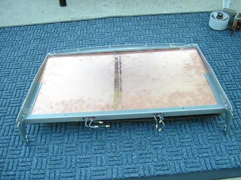
TPZ-32000721
Sep 14, 2006Antenna Array Controller
Equipment Class
DSS - Part 15 Spread Spectrum Transmitter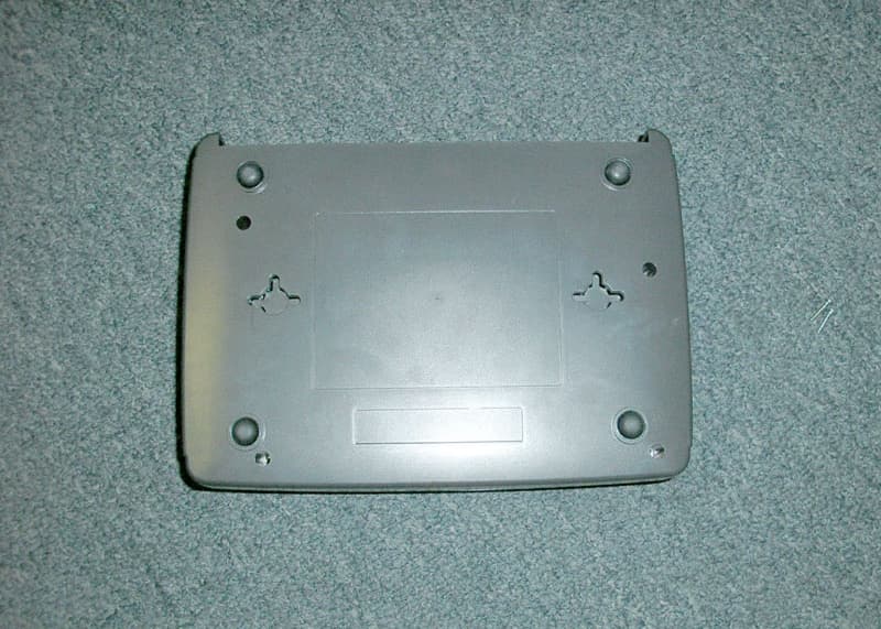
TPZ-34000003-001
Feb 01, 2006IntelliRouter
Equipment Class
DSS - Part 15 Spread Spectrum Transmitter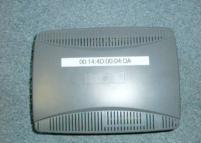
TPZ-34000002-001
Feb 01, 2006IntelliSwitch
Equipment Class
DXX - Part 15 Low Power Communication Device Transmitter