TS4-TW-221RDiversity Repeater
Tehama Wireless Design Group Inc.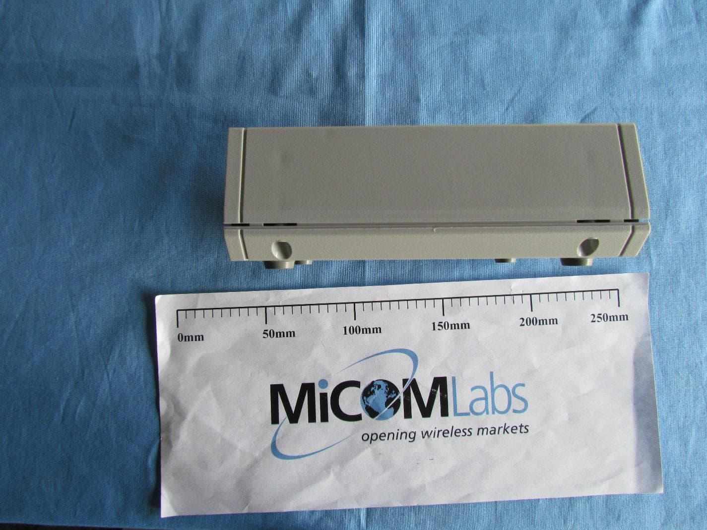
Click to zoom
Application Details
- Equipment Class
- DSS - Part 15 Spread Spectrum Transmitter
- Date of Grant
- May 12, 2015
- Application Purpose
- Original Equipment
- Date of Application
- May 12, 2015
- Equipment Note
- Diversity Repeater
- Frequency Range
- 903.00000000 - 926.00000000
- Country
- United States
Documents & Files
Document Text
Text extracted from the exhibit documents filed with the FCC. Open a document above to read the original.
Users Manual
Tehama System Installation Guide General Description The Tehama AMR system consists of three device types to remotely monitor various environmental and utility readings and provide the data to a central database or PC for formal presentation and reporting. Metering Data Transceiver (MDT) devices will be placed in all locations requiring local monitoring of data. The MDT devices will transmit time stamped data to the DCAP device, which receives the data and stores it in a Database. The database information is available over Ethernet on the local LAN or the Internet. For MDTs that are out of range from the DCAP, Repeater devices are added in appropriate locations to relay the data between MDTs and the DCAP The system operates in the 915Mhz ISM bands using off-the-shelf FSK RFIC radios. The system operates as a Frequency Hopper over 60 narrow band frequency channels, incorporating a bidirectional communication link with Acknowledge (ACK) messages to ensure all data reaches the DCAP. The MDTs are battery operated, bursting data packets at pre-programmed times then shutting down to conserve battery life, estimated to exceed 5 years. The DCAP and Repeater units are line powered. With an typical MDT transmission rate of four per hour for time of use applications, a single DCAP can accommodate up to 1000 MDTs. There is no limit to the number of repeaters, though an average installation may require one Repeater for every 20-30 MDT/MDTs. Figure 1: Typical System Tehama Installation Guide! of ! 16 A system consists of two or three types of hardware, and a software program: • One DCAP Unit or Access Point • A variable number of MDT units, each with 2 AA batteries • A variable number of Repeater units (optional, depending on size of installation) with external DC power supply. • Tehama Configuration Utility (CIT) running on a PC Warning Tehama Configuration & Installation Tool (CIT) You should have received a copy of the Tehama Configuration and Installation Tool (CIT) software. If not, please contact [email protected] and request the link. The CIT runs on a Windows based PC. More detailed information can be found in the Tehama CIT User Manual or the Tehama QuickStart Guide. The tool can be run on the PC either prior to or during a site installation, or when new MDTs are added to a system. The tool is used to add configuration data to the database. Examples of configuration data include the name, type, and location of equipment an MDT is connected to, and alarm trigger settings for the different MDTs. Data Collecting Access Point (DCAP) Setup This step configures the Internet settings for the DCAP and lets you set unique passwords for remote access. • Power up the DCAP with the supplied power adaptor. • Screw in the AP antenna that came with the unit. • Attach the supplied USB cable to your computer and to the AP. If this is the first time attaching tan AP, Windows may respond with a “found new hardware” message. Follow the steps to let Windows download the driver software. • Attach the AP to your local LAN with the supplied Ethernet cable. • Launch the CIT tool on the PC • Go to the Config menu and select DCAP. The Serial Port field should be automatically populated with the correct COM port • Click on the Get button to see the current settings • DCHP (Dynamic IP Address) is the default. If you want a static IP, select static and fill out the extra fields. Tehama Installation Guide! of ! 26 NOTE: THE MANUFACTURER IS NOT RESPONSIBLE FOR ANY RADIO OR TV INTERFERENCE CAUSED BY UNAUTHORIZED MODIFICATIONS TO THIS EQUIPMENT. SUCH MODIFICATIONS COULD VOID THE USER’S AUTHORITY TO OPERATE THE EQUIPMENT • Set the MySQL database passwords for both users and click “Set”. Clicking on the “Default Vals” button will fill the fields with the factory default passwords. This is provided as a convenience if password security is not an issue (for example in an evaluation system). • Click on the “Create a Site Entry” button to auto-fill a Site entry with the information from this panel. • Unplug the USB cable. It is not needed again unless you need to change the IP address or the database passwords at a future time. MDT Configuration All MDT come from the factory with a default factory-set configuration. The following parameters can be custom configured at the factory only; they cannot be changed by the user. There are no parameters which can be configured on the DCAP or Receiver. • Monitor Type, defined as the type of meter the MDT is attached to for readings. Our basic pulse MDT all work with 99% of the meters, but special units can be ordered for Hersey pulse meters, Encoder meters, etc. Additional data can be factory configured, such as temperature measurements. • Transmit Interval, defined as the time between scheduled transmissions of temperature data. Regular pulse meters transmit once every hour (60 minutes). Our Time of Use units are configured to transmit four times an hours (15 minutes). • Measure Interval, defined as the time between scheduled temperature measurements. This is used in conjunction with Temperature Change (see below) and must be smaller than the Transmit Interval time. A value of 0 for this parameter will disable measurements in between the Transmit Interval. The units for this parameter are in seconds, with default set to 0. • Temperature Change, defined as a percentage change in the Thermistor resistance value (i.e. temperature) detected by the MDT. A Delta Temp alarm will be generated within the PC Software if a MDT reading taken at a Measure Interval is more than Temperature Change percent from the prior Transmit Interval value. The units for this parameter are Percent (%), with the default value set to 0. Tehama Installation Guide! of ! 36 THIS DEVICE COMPLIES WITH PART 15 OF THE FCC RULES. OPERATION IS SUBJECT TO THE FOLLOWING TWO CONDITIONS: (1)THIS DEVICE MAY NOT CAUSE HARMFUL INTERFERENCE, AND (2)THIS DEVICE MUST ACCEPT ANY INTERFERENCE RECEIVED, INCLUDING INTERFERENCE THAT M…
Text truncated - open the document above for the full version.
Cover Letter(s)
Office of Engineering Technology Federal Communications Commission 7435 Oakland Mills Road Columbia, MD 21046 Subject; Request for Confidentiality FCC ID: TS4-TW-221R Date: April 22 nd 2015 To Whom It May Concern, Pursuant to the provisions of Sections 0.457 and 0.459 of Commission's rules (47CFR0.457, 0.459), we are requesting the Commission to withhold the following attachment(s) as confidential document from public disclosure indefinitely. Schematic Diagram Block Diagram Part List Operational Description Above mentioned document contains detailed system and equipment description are considered as proprietary information in operation of the equipment. The public disclosure of above documents might be harmful to our company and would give competitor an unfair advantage in the market. In additional to above mentioned documents, pursuant to Public Notice DA 04-1705 of the Commission' s policy, in order to comply with the marketing regulations in 47 CFT §2.803 and the importation rules in 47 CFR §2.1204, while ensuring that business sensitive information remains confidential until the actual marketing of newly authorized devices. We are requesting the commission to grant shot-term confidentiality request on the following attachment(s) for 180 days after the grant as outlined in Public Notice DA 04-1705. External Photos Internal Photos Test Setup Photos User Manual It is our understanding that all measurement test reports, FCC ID label format and correspondent during certification review process cannot be granted as confidential documents and those information will be available for public review once the grant of equipment authorization is issued. Sincerely, Name: Laurence Plouvier Title: Principal Design Engineer Signature:
Cover Letter(s)
Letter of Authorization Company: Tehama Wireless Address: 2607 7 th St, Suite G, Berkeley, CA 94710 Product Name: Diversity Repeater Model Number: TW-191-R FCC Identifier: TS4-TW-221R We authorize MiCOM Labs Inc, 575 Boulder Court, Pleasanton, California 94566, USA, to act on our behalf on all matters concerning the above named equipment. Any individual within MiCOM Labs is authorized to act on our behalf and take action on the application. We declare that MiCOM Labs Inc, 575 Boulder Court, Pleasanton, California 94566, USA, is allowed to forward all information related to the approval project to the Federal Communication Commission and to discuss any issues concerning the approval application. Any and all acts carried out by MiCOM Labs on our behalf shall have the same effect as acts of our own. Name: Laurence Plouvier Date: April 22 nd 2015 Title: Principal Design Engineer Signature of applicant:
External Photos
TEHA05 External Photograph Top View Bottom View Side 1 View Side 2 View Side 3 View Side 4 View
ID Label/Location Info
Spec for DivRepeater FCC Label Requirements: Size: 1 inch X 3 inches Material: Nylon or Mylar Bkgnd Color: Light grey or silver Text Color: Black Adhesive: Permanent, surface is a textured ABS plastic Permanence: The sticker should not be removable under normal circumstances. If removal is attempted, the label should break up (much like DMV License plate stickers do). Quantities: Quote for 500 pieces. Spec is identical (expect for text) to prior quote 44579. Text or artwork can be supplied. If artwork, please specify preferred format. Text is as follows: Repeater-2 Model TW-191-R FCC ID: TS4-TW-221R This device complies with Part 15 of the FCC Rules. Operation is subject to the following two conditions: (1) this device may not cause harmful interference, and (2) this device must accept any interference received, including interference that may cause undesired operation. 3 in DivRepeater Model TW-191-R FCC ID: TS4-TW-221R This device complies with Part 15 of the FCC Rules. Operation is subject to the following two conditions: (1) this device may not cause harmful interference, and (2) this device must accept any interference received, including interference that may cause undesired operation. 1 in 11, 10, and 6 Point fixed width font; can provide artwork to match DCAP-Fcc_Label! of ! 11
Internal Photos
TEHA05 Internal Photographs Bottom View PCB Top View PCB
RF Exposure Info
Maximum Permissible Exposure TEHA05-U2; Tehama Wireless TW-191-R FCC, Part 15 §1.1310 Industry Canada RSS-Gen §3.2 Calculations for Maximum Permissible Exposure Levels Power Density = Pd (mW/cm 2 ) = EIRP/(4d 2 ) EIRP = P * G P = Peak output power (mW) G = Antenna numeric gain (numeric) d = Separation distance (cm) Numeric Gain = 10 ^ (G (dBi)/10) Because the EUT belongs to the General Population/Uncontrolled Exposure the limit of power density is 1.0 mW/cm 2 The calculations in the table below use highest gain antennas for the client EUT. Where the antenna gain exceeds 6dBi the transmitter power is reduced where necessary to meet the EIRP requirements. These calculations represent worst case in terms of the exposure levels. Per FCC 1.1310 Power density Limit for device operating in frequency range 300 to 1500MHz = f/1500 (mW/cm 2 ) Freq. Band (MHz) Antenna Gain (dBi) Numeric Gain (numeric) Peak Output Power (dBm) Peak Output Power (mW) Calculated Safe Distance @ 0.6mW/cm 2 Limit(cm) Minimum Separation Distance (cm) 900 - 928 +2.5 1.78 25.81 381 9.5 20 Note: for mobile or fixed location transmitters the minimum separation distance is 20cm, even if calculations indicate the MPE distance to be less. Specification Maximum Permissible Exposure Limits FCC §1.1310 Limit = 1mW / cm 2 from 1.310 Table 1 RSS-Gen §3.2 The requirements in Radio Standards Specification RSS-102 shall be met. Laboratory Measurement Uncertainty for Power Measurements Measurement uncertainty 1.33 dB
Test Report
Company: Tehama Wireless Test of: TW-191-R Diversity Repeater To: FCC CFR 47 Part 15 Subpart C 15.247 (DTS) Report No.: TEHA05-U2 Rev A Conducted CONDUCTED TEST REPORT CONDUCTED TEST REPORT FROM Test of: Tehama Wireless TW-191-R Diversity Repeater to To: FCC CFR 47 Part 15 Subpart C 15.247 (DTS) Test Report Serial No.: TEHA05-U2 Rev A Conducted This report supersedes: None Applicant: Tehama Wireless 2607 7 th St. Suite G Berkeley California 94710 United States Product Function: Wireless signal repeater Issue Date: 1 st May 2015 This Test Report is Issued Under the Authority of: MiCOM Labs, Inc. 575 Boulder Court Pleasanton, California 94566 USA Phone: +1 (925) 462-0304 Fax: +1 (925) 462-0306 www.micomlabs.com MiCOM Labs is an ISO 17025 Accredited Testing Laboratory Title: Tehama Wireless TW-191-R Diversity Repeater To: FCC CFR 47 Part 15 Subpart C 15.247 (DTS) Serial #: TEHA05-U2 Rev A Conducted Issue Date: 1 st May 2015 Page: 3 of 47 This test report may be reproduced in full only. The document may only be updated by MiCOM Labs personnel. All changes will be noted in the Document History section of the report. MiCOM Labs, 575 Boulder Court, Pleasanton, California 94566 USA, Phone: +1 (925) 462 0304, Fax: +1 (925) 462 0306, www.micomlabs.com Contents 1. ACCREDITATION, LISTINGS & RECOGNITION ................................................................ 4 1.1. TESTING ACCREDITATION ........................................................................................ 4 1.2. RECOGNITION ............................................................................................................ 5 1.3. PRODUCT CERTIFICATION ....................................................................................... 6 2. DOCUMENT HISTORY........................................................................................................ 7 3. TEST RESULT CERTIFICATE ............................................................................................ 8 4. REFERENCES AND MEASUREMENT UNCERTAINTY ..................................................... 9 4.1. Normative References .................................................................................................. 9 4.2. Test And Uncertainty Procedure ................................................................................. 10 5. PRODUCT DETAILS AND TEST CONFIGURATIONS ..................................................... 11 5.1. Technical Details ........................................................................................................ 11 5.2. Scope Of Test Program .............................................................................................. 12 5.3. Equipment Model(s) and Serial Number(s) ................................................................. 13 5.4. Antenna Details .......................................................................................................... 13 5.5. Cabling and I/O Ports ................................................................................................. 13 5.6. Test Configurations .................................................................................................... 13 5.7. Equipment Modifications ............................................................................................ 14 5.8. Deviations from the Test Standard ............................................................................. 14 6. TEST SUMMARY .............................................................................................................. 15 7. TEST EQUIPMENT CONFIGURATION(S) ........................................................................ 16 8. MEASUREMENT AND PRESENTATION OF TEST DATA ............................................... 18 9. TEST RESULTS ................................................................................................................ 19 9.1. 20 dB & 99% Bandwidth ............................................................................................. 19 9.2. FHSS Transmitter Characteristics .............................................................................. 21 9.2.1. Frequency Hopping – Number Of Channels ............................................................ 22 9.2.2. Channel Spacing ..................................................................................................... 22 9.2.3. Dwell Time .............................................................................................................. 23 9.2.4. Channel Occupancy ................................................................................................ 23 9.3. Conducted Output Power ........................................................................................... 24 9.4. Conducted Spurious Emissions .................................................................................. 26 9.4.1. Conducted Spurious Emissions ............................................................................... 27 9.4.2. Conducted Band-Edge Emissions ........................................................................... 28 10. APPENDIX....................................................................................................................... 30 10.1. 20 dB & 99% Bandwidth ........................................................................................... 30 10.2. FHSS Transmitter Characteristics ............................................................................ 33 10.2.1. Frequency Hopping – Number Of Channels .......................................................... 33 10.2.2. Channel Spacing ................................................................................................... 36 10.2.3. Dwell Time ............................................................................................................ 37 10.2.4. Channel Occupancy .............................................................................................. 38 10.3. C…
Text truncated - open the document above for the full version.
Test Report
Company: Tehama Wireless Test of: TW-191-R Diversity Repeater To: FCC CFR 47 Part 15 Subpart C 15.247 (DTS) Report No.: TEHA05-U2 Rev A Radiated RADIATED TEST REPORT RADIATED TEST REPORT FROM Test of: Tehama Wireless TW-191-R Diversity Repeater to To: FCC CFR 47 Part 15 Subpart C 15.247 (DTS) Test Report Serial No.: TEHA05-U2 Rev A Radiated This report supersedes: None Applicant: Tehama Wireless 2607 7 th St. Suite G Berkeley California 94710 United States Product Function: Wireless signal repeater Issue Date: 1 st May 2015 This Test Report is Issued Under the Authority of: MiCOM Labs, Inc. 575 Boulder Court Pleasanton California 94566 USA Phone: +1 (925) 462-0304 Fax: +1 (925) 462-0306 www.micomlabs.com MiCOM Labs is an ISO 17025 Accredited Testing Laboratory Title: Tehama Wireless TW-191-R Diversity Repeater To: FCC CFR 47 Part 15 Subpart C 15.247 (DTS) Serial #: TEHA05-U2 Rev A Radiated Issue Date: 1 st May 2015 Page: 3 of 35 This test report may be reproduced in full only. The document may only be updated by MiCOM Labs personnel. All changes will be noted in the Document History section of the report. MiCOM Labs, 575 Boulder Court, Pleasanton, California 94566 USA, Phone: +1 (925) 462 0304, Fax: +1 (925) 462 0306, www.micomlabs.com Table of Contents 1. ACCREDITATION, LISTINGS & RECOGNITION................................................................................. 4 1.1. TESTING ACCREDITATION ......................................................................................................... 4 1.2. RECOGNITION ............................................................................................................................. 5 1.3. PRODUCT CERTIFICATION ........................................................................................................ 6 2. DOCUMENT HISTORY ......................................................................................................................... 7 3. TEST RESULT CERTIFICATE .............................................................................................................. 8 4. REFERENCES AND MEASUREMENT UNCERTAINTY ..................................................................... 9 4.1. Normative References ................................................................................................................... 9 4.2. Test and Uncertainty Procedure .................................................................................................. 10 5. PRODUCT DETAILS AND TEST CONFIGURATIONS ...................................................................... 11 5.1. Technical Details ......................................................................................................................... 11 5.2. Scope Of Test Program ............................................................................................................... 12 5.3. Equipment Model(s) and Serial Number(s) ................................................................................. 13 5.4. Antenna Details .......................................................................................................................... 13 5.5. Cabling and I/O Ports ................................................................................................................ 13 5.6. Test Configurations...................................................................................................................... 14 5.7. Equipment Modifications ............................................................................................................. 14 5.8. Deviations from the Test Standard .............................................................................................. 14 6. TEST SUMMARY ................................................................................................................................ 15 7. TEST EQUIPMENT CONFIGURATION(S) ......................................................................................... 16 8. TEST RESULTS .................................................................................................................................. 19 8.1. Emissions .................................................................................................................................... 19 8.1.1. Radiated Emissions .............................................................................................................. 19 8.1.2. Digital Emissions (0.03 - 1 GHz) ........................................................................................... 29 8.1.3. Conducted Disturbance at Mains Terminal (150 kHz – 30 MHz) ......................................... 32 Title: Tehama Wireless TW-191-R Diversity Repeater To: FCC CFR 47 Part 15 Subpart C 15.247 (DTS) Serial #: TEHA05-U2 Rev A Radiated Issue Date: 1 st May 2015 Page: 4 of 35 This test report may be reproduced in full only. The document may only be updated by MiCOM Labs personnel. All changes will be noted in the Document History section of the report. MiCOM Labs, 575 Boulder Court, Pleasanton, California 94566 USA, Phone: +1 (925) 462 0304, Fax: +1 (925) 462 0306, www.micomlabs.com 1. ACCREDITATION, LISTINGS & RECOGNITION 1.1. TESTING ACCREDITATION MiCOM Labs, Inc. is an accredited Electrical testing laboratory per the international standard ISO/IEC 17025:2005. The company is accredited by the American Association for Laboratory Accreditation (A2LA) www.a2la.org test laboratory number 2381.01. MiCOM Labs test schedule is available at the following URL; http://www.a2la.org/scopepdf/2381-01.pdf Title: Tehama Wireless TW-191-R Diversity Repeater To: FCC CFR 47 Part 15 Subpart C 15.247 (DTS) Serial #: TEHA05-U2 Rev A Radiated Issue Date: 1 st May 2015 Page: 5 of 35 This test report may be reproduced in full only. The document may only be updated by MiCOM Labs personnel. All changes will be noted in the Document History section of the report. MiCOM Labs, 575 Boulder Court, Pleasa…
Text truncated - open the document above for the full version.
Test Setup Photos
TEHA05 Test Set up Photos RF Conducted AC Wireline Side Rad Em 1-10G Back Rad Em 1-10G Front Rad Em 30-1000
Contact Information
Applicant
James Orton(President)
Technical Contact
Test Firm
Micom LabsGordon Hurst
Technical Specifications
| # | Rule Parts | Frequency Range | Power Output |
|---|---|---|---|
| 1 | 15C | 903 MHz - 926 MHz | 381.00 mW |
Other Applications from Tehama Wireless Design Group Inc.
TS4-TW-201
Feb 06, 2012Access Point
Equipment Class
DSS - Part 15 Spread Spectrum Transmitter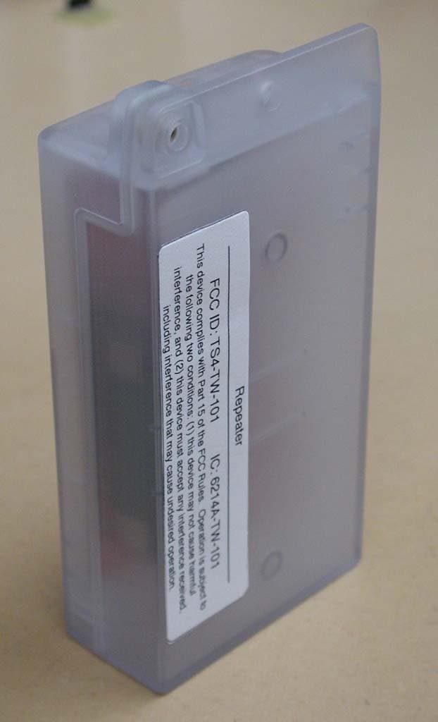
TS4-TW-101
Jan 11, 2011Repeater / Access Point
Equipment Class
DSS - Part 15 Spread Spectrum Transmitter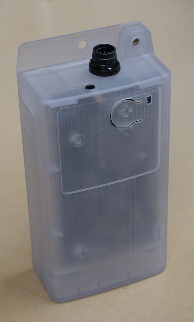
TS4-TW-100
Jan 11, 2011Remote Sensor
Equipment Class
DSS - Part 15 Spread Spectrum Transmitter
TS4-TWB-049
Jan 16, 2006Wireless Monitor System
Equipment Class
DSS - Part 15 Spread Spectrum Transmitter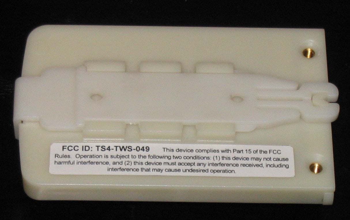
TS4-TWS-049
Nov 14, 2005TEMPERATURE SENSOR
Equipment Class
DSS - Part 15 Spread Spectrum Transmitter