TS4-TWS-049TEMPERATURE SENSOR
Tehama Wireless Design Group Inc.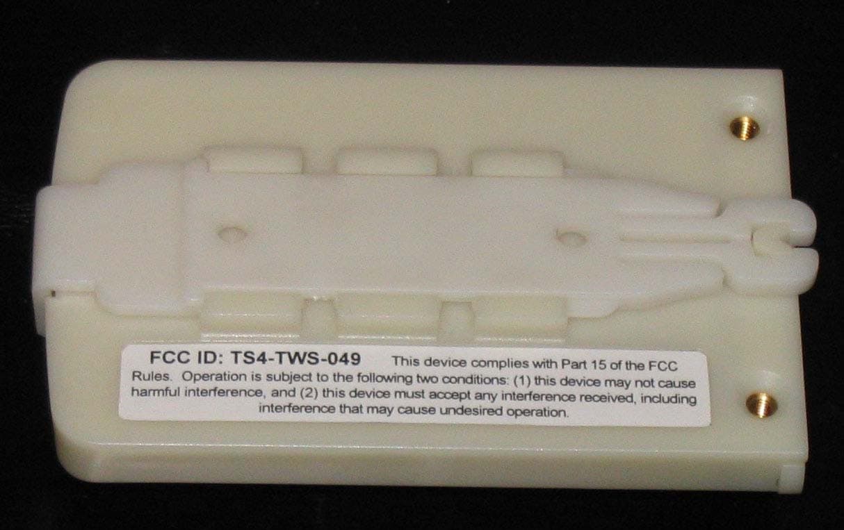
Click to zoom
Application Details
- Equipment Class
- DSS - Part 15 Spread Spectrum Transmitter
- Date of Grant
- Nov 14, 2005
- Application Purpose
- Original Equipment
- Date of Application
- Nov 14, 2005
- Equipment Note
- TEMPERATURE SENSOR
- Frequency Range
- 902.40000000 - 927.60000000
- Country
- United States
Documents & Files
Document Text
Text extracted from the exhibit documents filed with the FCC. Open a document above to read the original.
Users Manual
Tehama Wireless Design Group 11/14/2005 1 of 3 TempSens User Guide General Description The TempSens system consists of three device types to remotely monitor temperature readings and provide the data to a PC for formal presentation and reporting. Sensor devices will be placed in all locations requiring local monitoring of temperature. The Sensors will transmit time stamped temperature data to the single Base device in the system, which receives the data and forwards it to the host PC via a USB interface. For sensors that are out of range from the base, Repeater devices can be added in appropriate locations to relay the data between sensors and the base. The system will operate in the 865MHz (Europe/Asia) and 915Mhz (US) ISM bands using off the shelf FSK RFIC radios. The system will operate over 60 narrow band frequency channels with a baud rate of 4800bps, incorporating a bidirectional communication link with Acknowledge (ACK) messages to ensure all data reaches the base. The sensors are battery operated, bursting data packets at pre-programmed times then shutting down to conserve battery life, estimated to exceed 2 years. The repeaters will be line powered, while the base unit will be powered via line or USB interface used to communicate with the PC. With an average sensor transmission rate of four per hour, a single Base can accommodate many sensors. Through the use the ACK messages and local memory in both the sensors and repeaters (to store transmitted data that has not been confirmed as received by the base via an ACK message), the number of sensors supported can approach the theoretical maximum. There is no limit to the number of repeaters, though an average installation may require 1 repeater for every 10-15 sensors. Sensor Base Repeater iMac Repeater Repeater Sensor Sensor Sensor Sensor SensorSensor Sensor Sensor Sensor Sensor Sensor Sensor SensorSensorSensor Sensor Sensor Figure 1: Typical System Tehama Wireless Design Group 11/14/2005 2 of 3 A system consists of two or three types of hardware, and two pieces of software: • PC Database Software • Tehama Configuration Utility • One Base Unit with USB cable • A variable number of Sensors radios, each with 2 AA batteries • A variable number of Repeater radios (optional, depending on size of installation) with external DC power supply Warning Tehama Configuration Utility The following discussion assumes the base is connected a PC via the USB cable, and both the PC Database Software and the Tehama Configuration Utility are installed. This utility can be run on the PC either prior to or during a site installation, or when new sensors are added to a system. All sensors come from the factory with a default configuration, and the utility need not be run if no sensors are required to deviate from the default. The Utility will allow the following options to be configured on a sensor: • Transmit Interval, defined as the time between scheduled transmissions of temperature data. A temperature measurement is taken every Transmit Interval, and the data transmitted within 60 seconds after the measurement. The units for this parameter are seconds, and the default value is 900 seconds (15 minutes). • Measure Interval, defined as the time between scheduled temperature measurements. This is used in conjunction with Temperature Change (see below) and must be smaller than the Transmit Interval time. A value of 0 for this parameter will disable measurements in between the Transmit Interval. The units for this parameter are in seconds, with default set to 0. • Temperature Change, defined as a percentage change in the Thermistor resistance value (i.e. temperature) detected by the sensor. A Delta Temp alarm will be generated within the PC Software if a Sensor reading taken at a Measure Interval is more than Temperature Change percent from the prior Transmit Interval value. The units for this parameter are Percent (%), with the default value set to 0. No other parameters are configurable on the sensors. Absolutely no parameters are configurable on the Base or Receiver. NOTE: THE MANUFACTURER IS NOT RESPONSIBLE FOR ANY RADIO OR TV INTERFERENCE CAUSED BY UNAUTHORIZED MODIFICATIONS TO THIS EQUIPMENT. SUCH MODIFICATIONS COULD VOID THE USER’S AUTHORITY TO OPERATE THE EQUIPMENT Tehama Wireless Design Group 11/14/2005 3 of 3 Usage With the Configuration Utility running on the PC, the user will install batteries into the sensor to be configured and set the Power jumper (orange). This will cause the sensor to communicate to the base and provide the currently configured parameters along with the Sensor’s unique ID number. This information will be displayed in the Config Sensor tab of the Utility. The user should change the parameters as necessary, then hit the Set button to send the changes to the Sensor. The Sensor will receive the new data and store that data in non-volatile memory. Once a sensor has been configured, it will begin to operate normally, trying to send data as programmed and sleeping otherwise, however the PC software will not receive any data from the sensors until the Configuration Utility is closed. If the configuration is being performed away from the installation site, the battery or the orange jumper may be removed for shipment, as the new settings are stored permanently in the unit. Sensor Placement With the Base Unit plugged into the PC and the PC Software running, the Sensor placement phase begins. All the Sensors should be placed at the necessary locations, then the PC program should be checked to verify which Sensors are within range of the Base Unit. Alternatively an Installation monitor may be used that pings the base and all repeaters, providing audible and visual feedback of the signal strength. With this and/or a rough drawn map of each sensor’s location, the need for repeater placement is easily identified. After the repeater(s) have been installed, the user will again check the PC program to see an updated list unseen sensors. If th…
Text truncated - open the document above for the full version.
Block Diagram
TW-1020LP Radio PCB (Red) Micro 900MHz RFIC 4800 baud FSK 25KHz Channel Bandwidth Internal LC Oscillator 8MHz 32.736 KHz Crystal Sensor Inputs Tx Data Rx Data Radio Control 14.7456 MHz Crystal Switch Two AA Batteries Common Vcc Serial 1 SPI 2 RxD TxD Din Clk Dout Notes: 1: Serial Header use for engineering and test use only. Header will not be installed for Production Units 2: SPI port used to program Micro at production test. Socket will not be installed for Production units TWS-049 Sensor Block Diagram 902-928MHz Frequency Hopping Radio, +5dBm output Tehama Wireless Design Group 423 Tehama Street San Francisco, CA 94103 Chipcon CC1020 +5 dBm Output BP Filter
Cover Letter(s)
423 Tehama St. San Francisco, CA 94103 415 495 7344 (v) 415 495 7314 (f) Date: 1-November-2005 Subject: Confidentiality Request for Tempsens TWS-049, To Whom It May Concern: We hereby request under the provision of section 0.457(d) of the Commission’s Rules and Section 552(b)(4) of the Freedom of information Act [which authorizes withholding from public inspection materials which would be privileged as a matter of law] –Trade Secrets that the following information, submitted with the application for equipment authorization, be withheld from public disclosure. 1. Schematic Diagrams Sincerely, James Orton President, Tehama Wireless Design Group.
External Photos
FCC External Photographs for TempSens [FCC ID: TS4 – TWS-049] model TWS-049 - Sensor report number 20051019-01-Fc15 manufacturer Tehama Wireless Design Group 423 Tehama Street San Francisco, California, 94103 judgement Complies tests and report by ITC Engineering Services, Inc. (ITC) 9959 Calaveras Road, P.O. Box 543 Sunol, California 94586 Tel.: (925) 862-2944 Fax: (925) 862-9013 E-Mail: [email protected] Web Site: www.itcemc.com EN45001 Accredited Compliance Laboratory (RES-GmbH) Lab Code: 200172-0 Registration number: TTI-P-G 159/98-00 (RES-GmbH) Applicant: Tehama Wireless Design Group Report No.: 20051019-01-Fc15 Prepared By: ITC Engineering Services, Inc. 9959 Calaveras Road, PO Box 543 Sunol, California 94586-0543 Tel: [925] 862-2944 Fax: [925] 862-9013 Email: [email protected] Web: www.itcemc.com Product: TempSens Model(s): TWS-049 - Sensor FCC ID:TS4-TWS-049 Page 2 of 5 Table of Contents PART 1 GENERAL................................................................................................................................... 3 Section 1.1 General Information .............................................................................................................. 3 Section 1.2 Tests Performed: ................................................................................................................... 3 PART 2 EXTERNAL PHOTOGRAPHS ................................................................................................ 4 List of Figures Figure 1: EUT External View (Top) ................................................................................................................. 4 Figure 2: EUT External View (Bottom) ........................................................................................................... 4 Figure 3: EUT Component View 1 ................................................................................................................... 5 Applicant: Tehama Wireless Design Group Report No.: 20051019-01-Fc15 Prepared By: ITC Engineering Services, Inc. 9959 Calaveras Road, PO Box 543 Sunol, California 94586-0543 Tel: [925] 862-2944 Fax: [925] 862-9013 Email: [email protected] Web: www.itcemc.com Product: TempSens Model(s): TWS-049 - Sensor FCC ID:TS4-TWS-049 Page 3 of 5 PART 1 GENERAL SECTION 1.1 GENERAL INFORMATION Product Type Model(s) TempSens TWS-049 - Sensor Manufacturer’s Name Manufacturer’s Address Country Telephone and Fax Contact and Email Tehama Wireless Design Group. 423 Tehama Street San Francisco, California 94103 USA Tel: +1 (415) 495-7344 Mr. Jim Orton Fax: +1 (415) 495-7314 [email protected] Test Laboratory ITC Engineering Services, Inc. 9959 Calaveras Road, PO Box 543 Sunol, CA 94586-0543 Email: [email protected] Web Site: http://www.itcemc.com Tel: +1(925) 862-2944 Fax: +1(925) 862-9013 Test Number and Report Numbers 20051019-01 20051019-01-Fc15 Test Date(s) & Issue Date Oct. 27 th - Nov.2 nd of 2005 November 11 th , 2005 Test Engineer(s) Femi Ojo and Lan Vu Chief Engineer Michael Gbadebo, P.E Documentation George W Brown II. Test Results ; Complies as Tested Fail SECTION 1.2 TESTS PERFORMED: FCC Rules and Regulations per 47 CFR 15.247 Applicant: Tehama Wireless Design Group Report No.: 20051019-01-Fc15 Prepared By: ITC Engineering Services, Inc. 9959 Calaveras Road, PO Box 543 Sunol, California 94586-0543 Tel: [925] 862-2944 Fax: [925] 862-9013 Email: [email protected] Web: www.itcemc.com Product: TempSens Model(s): TWS-049 - Sensor FCC ID:TS4-TWS-049 Page 4 of 5 PART 2 EXTERNAL PHOTOGRAPHS Figure 1: EUT External View (Top) Figure 2: EUT External View (Bottom) Applicant: Tehama Wireless Design Group Report No.: 20051019-01-Fc15 Prepared By: ITC Engineering Services, Inc. 9959 Calaveras Road, PO Box 543 Sunol, California 94586-0543 Tel: [925] 862-2944 Fax: [925] 862-9013 Email: [email protected] Web: www.itcemc.com Product: TempSens Model(s): TWS-049 - Sensor FCC ID:TS4-TWS-049 Page 5 of 5 Figure 3: EUT Component View 1
ID Label/Location Info
FCC ID: TS4-TWS-049 This device complies with Part 15 of the FCC Rules. Operation is subject to the following two conditions: (1) this device may not cause harmful interference, and (2) this device must accept any interference received, including interference that may cause undesired operation.
Internal Photos
FCC Internal Photographs for TempSens [FCC ID: TS4 – TWS-049] model TWS-049 - Sensor report number 20051019-01-Fc15 manufacturer Tehama Wireless Design Group 423 Tehama Street San Francisco, California, 94103 judgement Complies tests and report by ITC Engineering Services, Inc. (ITC) 9959 Calaveras Road, P.O. Box 543 Sunol, California 94586 Tel.: (925) 862-2944 Fax: (925) 862-9013 E-Mail: [email protected] Web Site: www.itcemc.com EN45001 Accredited Compliance Laboratory (RES-GmbH) Lab Code: 200172-0 Registration number: TTI-P-G 159/98-00 (RES-GmbH) Applicant: Tehama Wireless Design Group Report No.: 20051019-01-Fc15 Prepared By: ITC Engineering Services, Inc. 9959 Calaveras Road, PO Box 543 Sunol, California 94586-0543 Tel: [925] 862-2944 Fax: [925] 862-9013 Email: [email protected] Web: www.itcemc.com Product: TempSens Model(s): TWS-049 - Sensor FCC ID:TS4-TWS-049 Page 2 of 6 Table of Contents PART 1 GENERAL................................................................................................................................... 3 Section 1.1 General Information .............................................................................................................. 3 Section 1.2 Tests Performed: ................................................................................................................... 3 PART 2 INTERNAL PHOTOGRAPHS ................................................................................................. 4 List of Figures Figure 1: EUT Internal View 1 ......................................................................................................................... 4 Figure 2: EUT Internal View 2 ......................................................................................................................... 4 Figure 3: EUT Internal View 3 ......................................................................................................................... 5 Figure 4: EUT Component View 2 ................................................................................................................... 5 Figure 5: EUT Component View 3 ................................................................................................................... 6 Applicant: Tehama Wireless Design Group Report No.: 20051019-01-Fc15 Prepared By: ITC Engineering Services, Inc. 9959 Calaveras Road, PO Box 543 Sunol, California 94586-0543 Tel: [925] 862-2944 Fax: [925] 862-9013 Email: [email protected] Web: www.itcemc.com Product: TempSens Model(s): TWS-049 - Sensor FCC ID:TS4-TWS-049 Page 3 of 6 PART 1 GENERAL SECTION 1.1 GENERAL INFORMATION Product Type Model(s) TempSens TWS-049 - Sensor Manufacturer’s Name Manufacturer’s Address Country Telephone and Fax Contact and Email Tehama Wireless Design Group. 423 Tehama Street San Francisco, California 94103 USA Tel: +1 (415) 495-7344 Mr. Jim Orton Fax: +1 (415) 495-7314 [email protected] Test Laboratory ITC Engineering Services, Inc. 9959 Calaveras Road, PO Box 543 Sunol, CA 94586-0543 Email: [email protected] Web Site: http://www.itcemc.com Tel: +1(925) 862-2944 Fax: +1(925) 862-9013 Test Number and Report Numbers 20051019-01 20051019-01-Fc15 Test Date(s) & Issue Date Oct. 27 th - Nov.2 nd of 2005 November 11 th , 2005 Test Engineer(s) Femi Ojo and Lan Vu Chief Engineer Michael Gbadebo, P.E Documentation George W Brown II. Test Results ; Complies as Tested Fail SECTION 1.2 TESTS PERFORMED: FCC Rules and Regulations per 47 CFR 15.247 Applicant: Tehama Wireless Design Group Report No.: 20051019-01-Fc15 Prepared By: ITC Engineering Services, Inc. 9959 Calaveras Road, PO Box 543 Sunol, California 94586-0543 Tel: [925] 862-2944 Fax: [925] 862-9013 Email: [email protected] Web: www.itcemc.com Product: TempSens Model(s): TWS-049 - Sensor FCC ID:TS4-TWS-049 Page 4 of 6 PART 2 INTERNAL PHOTOGRAPHS Figure 1: EUT Internal View 1 Figure 2: EUT Internal View 2 Applicant: Tehama Wireless Design Group Report No.: 20051019-01-Fc15 Prepared By: ITC Engineering Services, Inc. 9959 Calaveras Road, PO Box 543 Sunol, California 94586-0543 Tel: [925] 862-2944 Fax: [925] 862-9013 Email: [email protected] Web: www.itcemc.com Product: TempSens Model(s): TWS-049 - Sensor FCC ID:TS4-TWS-049 Page 5 of 6 Figure 3: EUT Internal View 3 1 Figure 4: EUT Component View 2 Applicant: Tehama Wireless Design Group Report No.: 20051019-01-Fc15 Prepared By: ITC Engineering Services, Inc. 9959 Calaveras Road, PO Box 543 Sunol, California 94586-0543 Tel: [925] 862-2944 Fax: [925] 862-9013 Email: [email protected] Web: www.itcemc.com Product: TempSens Model(s): TWS-049 - Sensor FCC ID:TS4-TWS-049 Page 6 of 6 Figure 5: EUT Component View 3
Operational Description
Tehama Wireless Design Group 11/7/2005 1 of 2 TW-049-S Sensor Operational Description The TWS-049 unit is a 902-298MHz frequency hopping transceiver consisting of the main micro board PCB and a low power radio module PCB. Features/Specs • The TWS-049 functions as a Remote Wireless Sensor, recording sensor data and wirelessly forwarding the data to the companion TWB-049 Base/Repeater units. • The system supports over 500 sensors with 15 minute transmission intervals. • An internal thermistor type sensor or external sensors are supported. • Powered by 2 AA batteries. • Battery life approximately 2 years with 15 minute measurement interval. • Jumper P2 acts as power switch (off w/o jumper) • The TWS-049 utilizes a Chipcon CC1020 RFIC (radio frequency integrated circuit) with maximum power output of +5dBm • Baud Rate = 4800 bps, Modulation is FSK with a 4.9kHz deviation • 60 channel frequency hopping system, minimum 400KHz channel separation • Dwell time per channel is 120mS maximum, 72mS typical • The TWS-049 is controlled via an 8 bit Atmel AVR micro (ATMega168V), clocked by its internal 8MHz LC oscillator. • The ATMega168V contains Flash ROM for program code, EEPROM for configuration/serial number, and SRAM for CPU operation, all internal to the IC • Real time clock maintained by 32.768KHz crystal Operation • The TWS-049 is configured by the user to measure attached sensors periodically with an interval time between 60 seconds and 18 hours. • At measurement intervals, sensor readings are taken by the micro and a data packet generated and queued up for transmission. The transmission time (and thereby channel selection) is chosen by a randomize function (seeded by the unit’s unique Serial ID) and a timer set to schedule the radio transmission. • At transmission time, receiver is first enabled to check for carrier detect (in case of interfering system or anther sensor). If carrier detect is clear, transmission proceeds. If another carrier is detected, transmission is delayed by approximately 100mS and the process repeated. If a carrier is detected the 2 nd time, the data is stored and the transmission rescheduled. • Upon transmission of data packet, the unit switches to receive mode to await the Acknowledge (ACK) packet from the Base/Repeater. If no ACK is seen, the data is stored in non-volatile memory for later transmission. • The TWS-049 can generate only one transmission per channel. • Typical configuration generates one transmission every 15 minutes • All transmitted packets incorporate a header that contains unique serial number ID of the transmitting unit. • The real time clock is synchronized via the acknowledge packet (ACK) from Base/Repeater. Tehama Wireless Design Group 11/7/2005 2 of 2 Clocks and Crystals: • 32.768KHz Crystal on Main PCB • 14.7456MHz Crystal on Radio PCB • SPI Clock line at 2MHz, active only when unit is transmitting Frequency Map Channel # Frequency MHz Separation KHz 0902.4 1902.8400 2903.2400 3903.6400 4904400 5904.4400 6904.8400 7905.4600 8905.8400 9906.2400 10906.6400 11907400 12907.4400 13907.8400 14908.4600 15908.8400 16909.2400 17909.6400 18910400 19910.4400 20910.8400 21911.4600 22911.8400 23912.2400 24912.6400 25913400 26913.4400 27913.8400 28914.4600 29914.8400 Channel # Frequency MHz Separation KHz 30915.2400 31915.6400 32916400 33916.4400 34916.8400 35917.4600 36917.8400 37918.2400 38918.6400 39919400 40919.4400 41919.8400 42920.4600 43920.8400 44921.2400 45921.6400 46922400 47922.4400 48922.8400 49923.4600 50923.8400 51924.2400 52924.6400 53925400 54925.4400 55925.8400 56926.4600 57926.8400 58927.2400 59927.6400 Typical Hopping Plan The hopping plan is generated from a randomize function by each unit upon reset, therefore is unique to each unit. This is a typical hopping plan: 47 -> 21 -> 50 -> 49 -> 58 -> 28 -> 57 -> 24 -> 43 -> 5 -> 33 -> 44 -> 19 -> 32 -> 45 -> 10 -> 2 -> 34 -> 31 -> 22 -> 37 -> 8 -> 16 -> 23 -> 1 -> 14 -> 27 -> 12 -> 6 -> 39 -> 0 -> 55 -> 52 -> 48 -> 30 -> 7 -> 51 -> 54 -> 56 -> 13 -> 18 -> 40 -> 41 -> 29 -> 36 -> 42 -> 59 -> 3 -> 9 -> 11 -> 20 -> 46 -> 35 -> 38 -> 4
Test Report
FCC Test Report for 47CFR15, Subpart B for Unintentional Radiators, per Section 101 Equipment authorization of unintentional radiators, and 47CFR15, Subpart C for Intentional Radiators, per Section 247 Operation within the bands 902 to 928 MHz on TempSens [FCC ID: TS4 – TWS-049] model TWS-049 - Sensor report number 20051019-01-Fc15 manufacturer Tehama Wireless Design Group 423 Tehama Street San Francisco, California, 94103 judgement Complies tests and report by ITC Engineering Services, Inc. (ITC) 9959 Calaveras Road, P.O. Box 543 Sunol, California 94586 Tel.: (925) 862-2944 Fax: (925) 862-9013 E-Mail: [email protected] Web Site: www.itcemc.com EN45001 Accredited Compliance Laboratory (RES-GmbH) Lab Code: 200172-0 Registration number: TTI-P-G 159/98-00 (RES-GmbH) Applicant: Tehama Wireless Design Group Report No.: 20051019-01-Fc15 Prepared By: ITC Engineering Services, Inc. 9959 Calaveras Road, PO Box 543 Sunol, California 94586-0543 Tel: [925] 862-2944 Fax: [925] 862-9013 Email: [email protected] Web: www.itcemc.com Product: TempSens Model(s): TWS-049 - Sensor FCC ID:TS4-TWS-049 Page 2 of 52 Table of Contents PART 1 GENERAL................................................................................................................................... 5 Section 1.1 General Information .............................................................................................................. 5 Section 1.2 Tests Performed: ................................................................................................................... 5 Section 1.3 Declaration/Disclaimer ......................................................................................................... 6 Section 1.4 Test Methodology ................................................................................................................. 7 Section 1.5 Accuracy of Test Data........................................................................................................... 7 Section 1.6 What is being Tested ............................................................................................................. 8 Section 1.7 EUT Ports and connectors..................................................................................................... 8 Section 1.8 List of peripherals used during Test...................................................................................... 8 Section 1.9 General Test Remarks ........................................................................................................... 8 Section 1.10 Test Equipment Used ............................................................................................................ 8 Section 1.11 Test Software Used ............................................................................................................... 9 Section 1.11 Test Summary and Results.................................................................................................... 9 PART 2 RECEIVER MEASUREMENTS ............................................................................................ 10 SECTION 2.0 OPEN FIELD RADIATED EMISSIONS per FCC Part 15b ................................... 10 Section 2.1 Test procedure ..................................................................................................................... 10 Section 2.2 Administrative And Environmental Details........................................................................ 10 Section 2.3 Test Equipment Used .......................................................................................................... 10 Section 2.4 Software Used ..................................................................................................................... 10 Section 2.5 Test Results ......................................................................................................................... 10 Section 2.6 Test Range (Radiated Emissions Tests) ..............................................................................11 Section 2.7 Spectrum Analyzer Configuration (swept frequency scans)- ............................................. 11 Section 2.8 Data Table Legend and Field Strength Calculation – Radiated Emissions Tests ............... 11 Section 2.9 Open Field Radiated Emission Test Results (Below 1 GHz) ............................................. 12 Section 2.10 Radiated Emissions Test Results (Above 1 GHz)............................................................... 12 Section 2.11 Test Data Summary............................................................................................................. 12 Section 2.12 Conclusion........................................................................................................................... 12 Section 2.13 Radiated Emissions Test Setup Photographs ...................................................................... 13 PART 3 RF MEASUREMENTS ............................................................................................................ 15 Section 3.1 List of Support equipment used during RF Tests................................................................ 15 Section 3.2 Test Equipment Used .......................................................................................................... 15 Section 3.3 Software Used ..................................................................................................................... 15 Section 3.4 Data Table Legend and Field Strength Calculation ............................................................ 15 Section 3.5 Setup Photographs............................................................................................................... 16 PART 4 NUMBER OF HOPPING FREQUENCIES MEASUREMENT per 15.247 (a) ................. 18 Section 4.1 Test Setup And Procedure................................................................................................... 18 Section…
Text truncated - open the document above for the full version.
Test Setup Photos
FCC Test Setup Photographs for 47CFR15, Subpart B for Unintentional Radiators, per Section 101 Equipment authorization of unintentional radiators, and 47CFR15, Subpart C for Intentional Radiators, per Section 247 Operation within the bands 902 to 928 MHz on TempSens [FCC ID: TS4 – TWS-049] model TWS-049 - Sensor report number 20051019-01-Fc15 manufacturer Tehama Wireless Design Group 423 Tehama Street San Francisco, California, 94103 judgement Complies tests and report by ITC Engineering Services, Inc. (ITC) 9959 Calaveras Road, P.O. Box 543 Sunol, California 94586 Tel.: (925) 862-2944 Fax: (925) 862-9013 E-Mail: [email protected] Web Site: www.itcemc.com EN45001 Accredited Compliance Laboratory (RES-GmbH) Lab Code: 200172-0 Registration number: TTI-P-G 159/98-00 (RES-GmbH) Applicant: Tehama Wireless Design Group Report No.: 20051019-01-Fc15 Prepared By: ITC Engineering Services, Inc. 9959 Calaveras Road, PO Box 543 Sunol, California 94586-0543 Tel: [925] 862-2944 Fax: [925] 862-9013 Email: [email protected] Web: www.itcemc.com Product: TempSens Model(s): TWS-049 - Sensor FCC ID:TS4-TWS-049 Page 2 of 9 Table of Contents PART 1 GENERAL................................................................................................................................... 3 Section 1.1 General Information .............................................................................................................. 3 Section 1.2 Tests Performed: ................................................................................................................... 3 PART 2 TEST SETUP PHOTOGRAPHS .............................................................................................. 4 Section 2.1 Radiated Emissions Test Setup Photographs ........................................................................ 4 Section 2.2 RF Conducted Emissions Test Setup Photographs ............................................................... 6 Section 2.3 Spurious EMISSIONS TEST SETUP Photographs.............................................................. 8 List of Figures Figure 1: Radiated Emissions Test Setup (Below 1 GHz) Front View ............................................................ 4 Figure 2 Radiated Emissions Test Setup (Below 1 GHz) closed up view........................................................ 4 Figure 3: Radiated Emissions Test Setup (Above 1 GHz) Front View ............................................................ 5 Figure 4: Radiated Emissions Test Setup (Above 1 GHz) Rear View ............................................................. 5 Figure 5 Test Set Up Photo – Front View......................................................................................................... 6 Figure 6 Test Set Up Photo (Front Close up View).......................................................................................... 6 Figure 7 Test Set Up Photo (Rear View) .......................................................................................................... 7 Figure 8: Spurious Emissions Front View (Below 1 GHz) ............................................................................. 8 Figure 9: Spurious Emissions Rear View (Below 1 GHz) .............................................................................. 8 Figure 10: Spurious Emissions Front View (Above 1 GHz) ........................................................................... 9 Figure 11: Spurious Emissions Rear View (Above 1 GHz) ............................................................................ 9 Applicant: Tehama Wireless Design Group Report No.: 20051019-01-Fc15 Pr…
Text truncated - open the document above for the full version.
Contact Information
Applicant
James Orton(President)
Test Firm
ITC Engineering Services, Inc.Michael Gbadebo
Technical Specifications
| # | Rule Parts | Frequency Range | Power Output |
|---|---|---|---|
| 1 | 15C | 902.4 MHz - 927.6 MHz | 5.60 mW |
Other Applications from Tehama Wireless Design Group Inc.
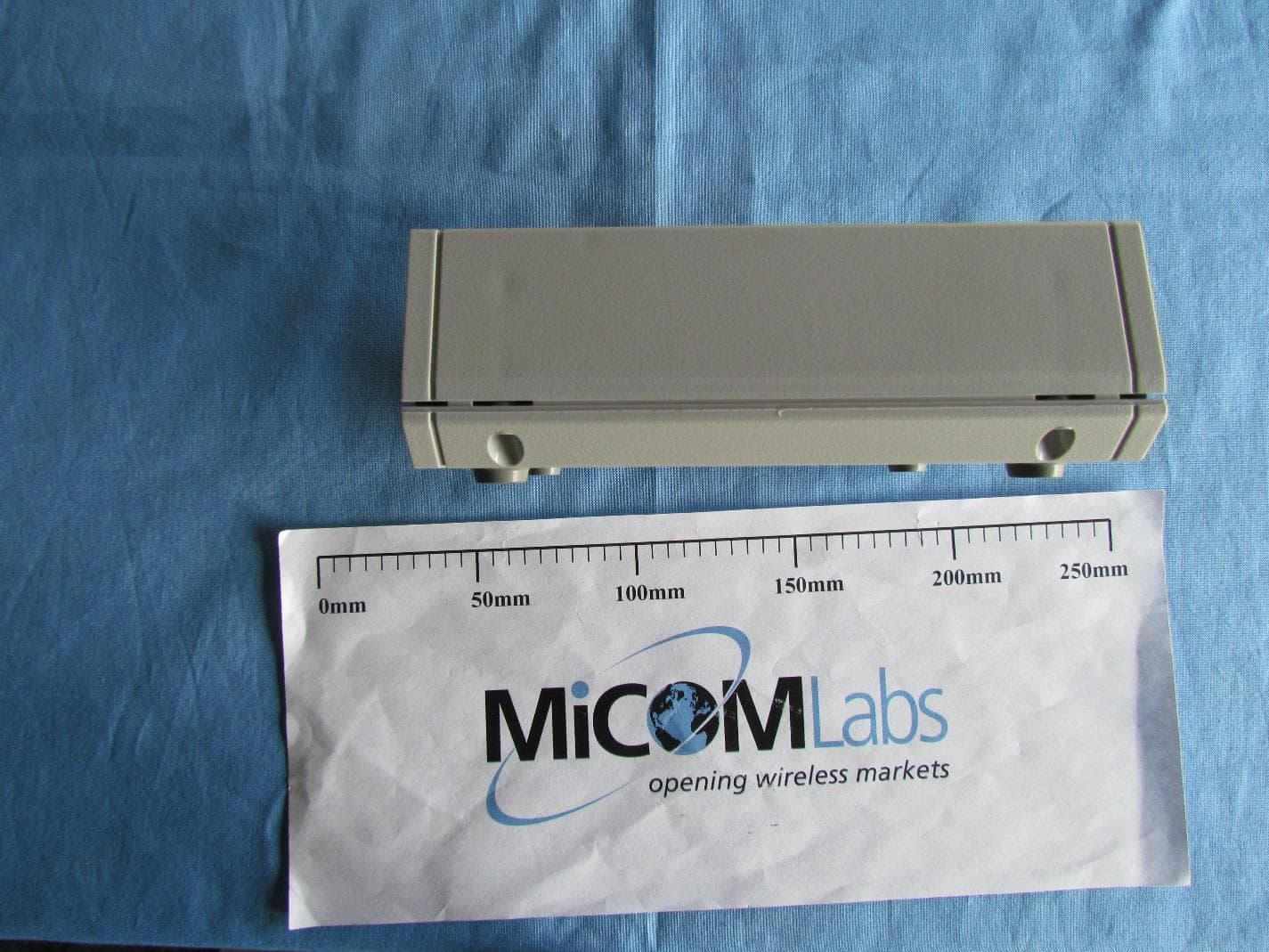
TS4-TW-221R
May 12, 2015Diversity Repeater
Equipment Class
DSS - Part 15 Spread Spectrum Transmitter
TS4-TW-201
Feb 06, 2012Access Point
Equipment Class
DSS - Part 15 Spread Spectrum Transmitter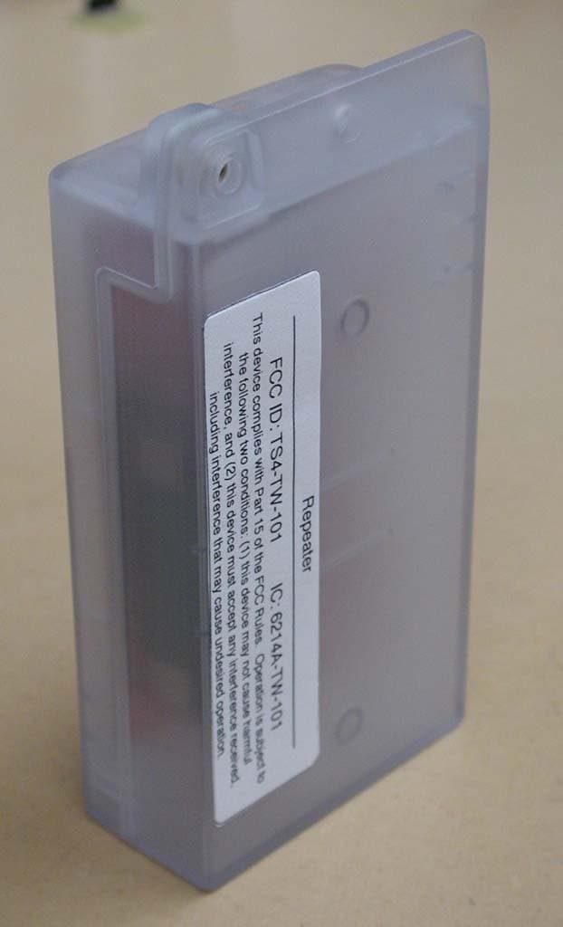
TS4-TW-101
Jan 11, 2011Repeater / Access Point
Equipment Class
DSS - Part 15 Spread Spectrum Transmitter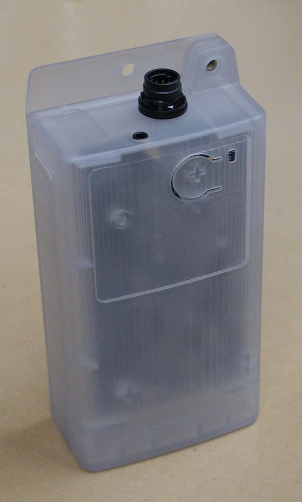
TS4-TW-100
Jan 11, 2011Remote Sensor
Equipment Class
DSS - Part 15 Spread Spectrum Transmitter
TS4-TWB-049
Jan 16, 2006Wireless Monitor System
Equipment Class
DSS - Part 15 Spread Spectrum Transmitter