TTI-SL24G-US-0124 GHz Point-to-Point High Speed Radio Link
Hitachi Kokusai Electric Inc.
Click to zoom
Application Details
- Equipment Class
- DXT - Part 15 Low Power Transceiver, Rx Verified
- Date of Grant
- Mar 16, 2006
- Application Purpose
- Original Equipment
- Date of Application
- Mar 16, 2006
- Equipment Note
- 24 GHz Point-to-Point High Speed Radio Link
- Frequency Range
- 24080.00000000 - 24220.00000000
- Country
- Japan
Documents & Files
Document Text
Text extracted from the exhibit documents filed with the FCC. Open a document above to read the original.
Users Manual
150Mbps High-speed Radio Link User’s Manual Please read ahead of the use. SINELINK24G Caution: Changes or modifications not expressly approved by Hitachi Kokusai Electric Inc. could void the user's authority to operate the equipment. Note: This equipment has been tested and found to comply with the limits for a Class A digital device, pursuant to part 15 of the FCC Rules. These limits are designed to provide reasonable protection against harmful interference when the equipment is operated in a commercial environment. This equipment generates, uses, and can radiate radio frequency energy and, if not installed and used in accordance with the instruction manual, may cause harmful interference to radio communications. Operation of this equipment in a residential area is likely to cause harmful interference in which case the user will be required to correct the interference at his own expense. SINELINK24G 1. INTRODUCTION ............................................................................1 1-1 TARGETS.....................................................................................1 1-2 PRODUCT SUMMARY.....................................................................1 1-3 FEATURES...................................................................................1 1-7 NAME AND EXPLANATION OF MAIN BODY EACH PART.......................2 1-8 DIRECTIVITY OF ANTENNA.............................................................3 1-9 CONNECTING SINELINK24G.......................................................4 2. INSTALLATION, CONNECTION, SETTING..................................5 2-1 INSTALLATION FLOW.....................................................................5 2-2 SETTING UP FROM PC ..................................................................6 2-3 PREPARATION FOR INSTALLATION. ............................................... 11 2-4 INSTALLATION............................................................................12 2-5 CONNECT TO LAN EQUIPMENTS.................................................20 2-6 CONFIRM THE RF STATUS...........................................................20 3. USE OF THIS DEVICE.................................................................21 3-1 POWER-ON...............................................................................21 3-2 POWER-OFF..............................................................................21 3-3 MAINTENANCE BY WWW BROWSER...........................................21 4. APPENDIX....................................................................................33 4-1 SPECIFICATION..........................................................................33 4-2 RF CHANNEL ALLOCATION NUMBER.............................................35 4-8 FACTORY DEFAULT.....................................................................36 SINELINK24G 1 1. INTRODUCTION This manual describes the use of SINELINK24G. Please read this manual carefully before using the equipment. 1-1 Targets This manual targets the engineer who has knowledge of LAN, TCP/IP, and a WWW browser at the business level. 1-2 Product summary * Using unlicensed 24GHz band, everybody can use SINELINK and install anywhere. * The through-put achieves 56Mbps for each uplink and downlink. * Wireless communication circuit enables high-speed data communication system in areas where wire circuit installation is not available, due to obstacles such as rivers, railroad, principal road, etc.. 1-3 Features (1) 150Mbps high-speed transmission ¾ 150Mbps radio transmission speed as optic fiber ¾ Enough effective through-put to achieve transmission of moving image etc. (2) Unlicensed and uncrowded 24GHz band ¾ Enough channels availability (8ch) ¾ Dynamic frequency selection function (Avoid using interfered channel and enable the stable circuit quality) ¾ No license required, you can use SINELINK if only the installation has been done. (3) High security ¾ Data is scrambled ¾ Unique and nonpublic radio protocol * This secures important data ¾ Pencil beam antenna (3.5 degrees or less) * Narrow beam prevents unexpected receiver (4) Easy installation (Note 1) ¾ Compact and light weight * 29 x 29 x 7cm, Approx. 3kg (Antenna is contained) ¾ Easy direction tuning by watching hole only ¾ Compliant with IEEE802.3af ¾ Parameter setting and status confirmation by PC Web style input only (Note 1) Communication cannot be performed under the condition that opposite product is unseeable. SINELINK24G 2 1-7 Name and explanation of main body each part Name explanation (a) Antenna The radio wave emits from the antenna side. The antenna side is turned to the opposing device for set up. (b) Direction Adjustment ScopeBy looking from the hole in scope, the direction of this antenna is adjusted. (c) Heat radiation fin integrated back lid It releases internal heat into air. (d) Mount bracket It fixes this device to pole. The diameter of a pole is 25 ~ 45mm. (e) LAN connecter Connect LAN cable. At the outdoor installation, connect LAN cable with waterproofing cap. (f) The atmospheric pressure adjustment hole The atmospheric pressure in this product is adjusted. (g) GND (FG) Terminal Connect grounding wire. (a) (b) (c) (d) (b) (d) (e) (f) (g) approximately 29cm approximately 29cm approximately 7cm approximately 8cm SINELINK24G 3 1-8 Directivity of antenna Directivity of antenna Horizontal direction 0.5° Vertical direction 0.5° Antenna pattern -50 -45 -40 -35 -30 -25 -20 -15 -10 -5 0 -30-20-100102030 Angle(degree) Gain(dB) -8 -7 -6 -5 -4 -3 -2 -1 0 -2-1012 Angle(degree) Gain(dB) SINELINK24G 4 1-9 Connecting SINELINK24G Connected composition example is shown below. * Example1 When you use PoE-PSE Adapter * Example2 When you use PoE-PSE Switching-HUB (1) The communication distance between this product and opposite product is 5 ~ 2000m (recommendation). (2) This product connects with PoE-PSE. Maximum cable length that adds (2) to (3) is 100m. Please use the STP cable and the serge protective device w…
Text truncated - open the document above for the full version.
External Photos
SINELINK24G (1/4) External photos November 23, 2005 Hitachi Kokusai Electric Inc. Product Name : SINELINK 24G Model No :HP5-110100 1. External photo 1 Photo.1 Front view SINELINK 24G Direction Adjustment Scope SINELINK24G (2/4) 2. External photo 2 Photo.2 Rear view SINELINK 24G Mount bracket Direction Adjustment Scope Zoom LAN connecter GND (FG) Terminal The atmospheric pressure adjustment hole SINELINK24G (3/4) 3. External photo 3 Photo.3 Side view SINELINK 24G SINELINK24G (4/4) 4. External figure 1 (mm) (mm)
ID Label/Location Info
SINELINK24G (1/1) FCCID Label Location Product Name : SINELINK 24G Model No :HP5-110100 (mm) (mm) FCCID Label
Internal Photos
SINELINK24G (1/6) Internal photos March 9, 2006 Hitachi Kokusai Electric Inc. Product Name : SINELINK 24G Model No :HP5-110100 1. Internal photos explanation 1 Planar antenna 552 unit Fig.1 SINELINK24G (2/6) 2. Internal photos explanation 2 CONT unit Fig.2 PD unit SINELINK24G (3/6) 3. Internal photos explanation 3 RF unit Fig.3 Antenna rear view Planar antenna 552 unit SINELINK24G (4/6) 4. Internal photos explanation 4 Fig.4 All parts Planar antenna 552 unit RF unit Radome CONT unit PD unit SINELINK24G (5/6) 5. Internal photos explanation 5 CONT unit rear view PD unit rear view Fig.5 SINELINK24G (6/6) 6. Internal photos explanation 6 RF board front view RF board rear view Fig.6
Test Report
Report Number 3086827BOX.014 Page 2 of 40 1.0 Job Description 1.1 Client Information This EUT has been tested at the request of: Company: Hitachi Telecom (USA), Inc. #17855 3617 Parkway Lane Suite 100 Norcross, GA 30092 Contact: Nick Yasui Telephone: Fax: Email: 770-797-2530 770-797-2555 [email protected] 1.2 Equipment Under Test Equipment Type: SINELINK 24G 150Mbps High-Speed Radio Link Model Number(s): HP5-110100 Serial number(s): ES001 Manufacturer: Hitachi Kokusai Electric Inc. EUT receive date: 12/05/2005 EUT received condition: Prototype in Good condition Test start date: 12/05/2005 Test end date: 3/09/2006 1.3 Test Plan Reference: Tested according to the standards listed and ANSI C63.4:2003. 1.4 Test Configuration 1.4.1 Block Diagram Turntable SINELINK PoE In jector Data Cable Ground AC power outlet (power for PoE and grounding for SINELINK Ethernet to remote laptop Report Number 3086827BOX.014 Page 3 of 40 1.4.2. Cables: Cable Shielding Connector Length (m) Qty. Ground Wire None Plastic 1.5 1 AC Cable None Plastic 1.5 1 Ethernet Cable to PC None Plastic 4 1 Ethernet Data Cable from SINELINK to PoE Injector Foil Metal/RJ45 1.9 1 1.4.3. Support Equipment: Name: Model No.: Serial No.: Buffalo Power over Ethernet Injector BIJ-POE-1P 36466754310706 Name: Model No.: Serial No.: Dell Laptop PP10L N/L Name: Model No.: Serial No.: Dell AC Adapter PA-1650-05D N/L 1.5 Mode(s) of Operation: The EUT was activated from nominal power, and was transmitting continuously with QPSK, QAM16, or QAM64 modulation during RF output power and spurious emissions testing. During the frequency stability test, the EUT was transmitting a continuous wave carrier. During the AC line-conducted emissions test, the EUT was activated at nominal power from the Buffalo power over ethernet injector and was continuously transmitting. The data terminal of the power over ethernet injector was terminated with a loopback. Report Number 3086827BOX.014 Page 4 of 40 2.0 Test Summary TEST STANDARD RESULTS FCC CFR47 Part 15 Subpart C 15.249 SUB-TEST TEST PARAMETER COMMENT RF Output Power FCC 15.249(b)(1),(b)(3) Field strength of fundamental emissions from fixed point- to-point transmitters operating in the band from 24.05 – 24.25 GHz shall not exceed 2500 mV/m (128 dBuV/m). Antenna gain must be at least 33 dBi, and the main lobe beam width must not exceed 3.5 degrees. Pass Occupied Bandwidth FCC 15.215 The 20 dB bandwidth of the fundamental emissions must stay between 24.05 and 24.25 GHz. Pass Band Edge Compliance FCC 15.215, 15.249(d) The average value of spurious emissions at the band edges must be attenuated at least 50 dB below the peak level of the fundamental emission. Pass Radiated Spurious Emissions, 30 MHz – 40 GHz FCC 15.205, 15.209, 15.249(a-e) Harmonic emissions must not exceed 2500uV/m (68 dBuV/m). Emissions radiated outside of the specified frequency bands, except for harmonics, shall be attenuated by at least 50 dB below the level of the fundamental or to the general radiated emission limits in 15.209, whichever is the lesser attenuation. Field strength limits are specified at a distance of 3 meters. Emissions falling into the restricted bands of 15.205 must meet the general limits of 15.209. Pass Radiated Spurious Emissions, 40 – 100 GHz FCC 15.205, 15.209, 15.249(a-e) Harmonic emissions must not exceed 2500uV/m (68 dBuV/m). Emissions radiated outside of the specified frequency bands, except for harmonics, shall be attenuated by at least 50 dB below the level of the fundamental or to the general radiated emission limits in 15.209, whichever is the lesser attenuation. Field strength limits are specified at a distance of 3 meters. Emissions falling into the restricted bands of 15.205, except for harmonics in the 48.0–48.5 GHz and 72.0–72.75 GHz bands only, must meet the general limits of 15.209. Pass Frequency Stability FCC 15.249(b)(2) The frequency tolerance of the carrier signal shall be maintained within ±0.001% of the operating frequency over a temperature variation of -20 degrees to +50 degrees C at normal supply voltage, and for a variation in the primary supply voltage from 85% to 115% of the rated supply voltage at a temperature of 20 degrees C. Pass AC Line-Conducted Emissions FCC 15.207 AC line-conducted emissions must not exceed the limits of FCC 15.207. Pass Report Number 3086827BOX.014 Page 5 of 40 Notes: The EUT operates with QAM16, QAM64, and QPSK modulations. Antenna Gain: 35 dBi Antenna Beam Width: 2.8 degrees Channels 1, 4, and 8 were selected for test. Channel 1: 24080 MHz Channel 4: 24140 MHz Channel 8: 24220 MHz REVISION SUMMARY – The following changes have been made to this Report: Date Project No. Project Handler Page(s) Item Description of Change Report Number 3086827BOX.014 Page 6 of 40 3.0 Sample Calculations The field strength is calculated by adding the Antenna Factor and Cable Factor, and subtracting the Amplifier Gain (if any) from the measured reading. The basic equation with a sample calculation is as follows: FS = RA + AF + CF - AG Where FS = Field Strength in dBμV/m RA = Receiver Amplitude (including preamplifier) in dBμV CF = Cable Attenuation Factor in dB AF = Antenna Factor in dB AG = Amplifier Gain in dB In the following table(s), the reading shown on the data table reflects the preamplifier gain. An example for the calculations in the following table is as follows. Assume a receiver reading of 52.0 dBμV is obtained. The antenna factor of 7.4 dB and cable factor of 1.6 dB is added. The amplifier gain of 29 dB is subtracted, giving a field strength of 32 dBμV/m. This value in dBμV/m was converted to its corresponding level in μV/m. RA = 52.0 dBμV AF = 7.4 dB/m CF = 1.6 dB AG = 29.0 dB FS = 32 dBμV/m Level in μV/m = [10( 32 dBμV/m)/20] = 39.8 μV/m The following is how net line-conducted readings were determined: NF = RF + LF + CF + AF Where NF = Net Reading in dBμV RF = Reading from receiver in dBμV LF = LISN Correction Factor in dB CF = Cable Correction Factor in dB AF = Attenua…
Text truncated - open the document above for the full version.
Test Setup Photos
Report Number 3086827BOX.014 Page 31 of 40 Setup Photos Report Number 3086827BOX.014 Page 32 of 40 Report Number 3086827BOX.014 Page 39 of 40 Setup Photos Report Number 3086827BOX.014 Page 40 of 40
Contact Information
Applicant
Takashi Okada(Assistant Manager)
Technical Contact
Hitachi Kokusai Electric Inc.Kanemi Sasaki
[email protected]81-42-322-3111
32 Miyuki-cho, Kodaira-shi · Tokyo · Japan
Non-Technical Contact
Hitachi Kokusai Electric Inc.Yoshiya Hashimoto
[email protected]81-3-6734-9502
Test Firm
Intertek Testing Services NA Inc.Yaqing Liu
[email protected]978 635 8662
Technical Specifications
| # | Rule Parts | Frequency Range | Power Output | Tolerance |
|---|---|---|---|---|
| 1 | 15C | 24.08 GHz - 24.22 GHz | - | 10.0000000000 ppm |
Other Applications from Hitachi Kokusai Electric Inc.
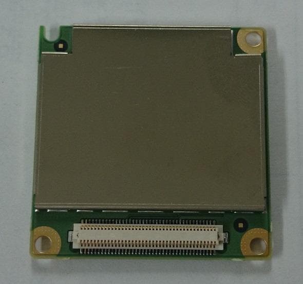
TTIUM04KO
Sep 20, 2015Wireless Communication Module
Equipment Class
PCB - PCS Licensed Transmitter
TTI-SL24G-US-02
Feb 16, 2012SINELINK 24G Point-to-Point Radio (HP5-120100)
Equipment Class
DXT - Part 15 Low Power Transceiver, Rx Verified