TV7-TB5ITG-BT5-IN
Mikrotikls SIA
Click to zoom
Application Details
- Equipment Class
- DTS - Digital Transmission System
- Date of Grant
- Jun 02, 2021
- Application Purpose
- Original Equipment
- Date of Application
- Jun 01, 2021
- Equipment Note
- TG-BT5-IN
- Frequency Range
- 2402.00000000 - 2480.00000000
- Company
- Mikrotikls SIA
- Country
- Latvia
Documents & Files
Document Text
Text extracted from the exhibit documents filed with the FCC. Open a document above to read the original.
Users Manual
EN - English - Quick Guide: This series Quick Guide covers models: TG-BT5-IN. This is a wireless network device. You can find the product model name on the case label (ID). Please visit the user manual page on for the full up-to-date user manual. Or scan the QR code with your mobile phone.https://mt.lv/um Full technical specifications, brochures, and more info about products at https://mikrotik.com/products Configuration manual for software in your language with additional information can be found at https://mt.lv/help If you need help with configuration, please seek a consultant https://mikrotik.com/consultants This Wireless product is featuring Bluetooth® technology. First steps: Use a mobile application https://mikrotik.com/mobile_app Follow the configuration guide https://help.mikrotik.com/docs/display/UM/TG-BT5-IN Safety Information: Before you work on any MikroTik equipment, be aware of the hazards involved with electrical circuitry, and be familiar with standard practices for preventing accidents. The installer should be familiar with network structures, terms, and concepts. Use only the power supply and accessories approved by the manufacturer, and which can be found in the original packaging of this product. This equipment is to be installed by trained and qualified personnel, as per these installation instructions. The installer is responsible for making sure, that the Installation of the equipment is compliant with local and national electrical codes. Do not attempt to disassemble, repair, or modify the device. This product is intended to be installed indoors. Keep this product away from water, fire, humidity, or hot environments. We cannot guarantee that no accidents or damage will occur due to the improper use of the device. Please use this product with care and operate at your own risk! In the case of device failure, please disconnect it from power. The fastest way to do so is by unplugging the power adapter from the power outlet. This is a Class B product. In a domestic environment, this product might cause radio interference in which case the user might be required to take adequate measures. This MikroTik equipment complies with the FCC, IC, and European Union radiation exposure limits set forth for anExposure to Radio Frequency Radiation: uncontrolled environment. This MikroTik device should be installed and operated no closer than 20 centimeters from your body, occupational user, or the general public. Manufacturer: Mikrotikls SIA, Brivibas gatve 214i Riga, Latvia, LV1039. BG - Български. Бързо ръководство: Тази серия Кратко ръководство обхваща модели: TG-BT5-IN. Това е безжично мрежово устройство.Името на модела на продукта можете да намерите на етикета на калъфа (ID). Моля, посетете страницата с ръководството за потребителя на за пълното актуално ръководство за потребителя.Илиhttps://mt.lv/um сканирайте QR кода с мобилния си телефон. Пълни технически спецификации, брошури и повече информация за продуктите на https://mikrotik.com/products Ръководство за конфигуриране на софтуер на вашия език с допълнителна информация можете да намерите наhttps://mt.lv/help-bg Ако имате нужда от помощ при конфигурирането, моля, потърсете консултант https://mikrotik.com/consultants Този безжичен продукт се отличава с технологията Bluetooth®. Първи стъпки: Използвайте мобилно приложение https://mikrotik.com/mobile_app Следвайте ръководството за конфигуриране https://help.mikrotik.com/docs/display/UM/TG-BT5-IN Информация за безопасност: Преди да работите с всяко оборудване на MikroTik, имайте предвид опасностите, свързани с електрическата верига, и се запознайте със стандартните практики за предотвратяване на злополуки.Инсталаторът трябва да е запознат с мрежовите структури, термини и понятия. Използвайте само захранването и аксесоарите, одобрени от производителя, и които можете да намерите в оригиналната опаковка на този продукт. Това оборудване трябва да се монтира от обучен и квалифициран персонал съгласно тези инструкции за монтаж.Инсталаторът отговаря за това, че инсталирането на оборудването е в съответствие с местните и националните електрически кодове.Не се опитвайте да разглобявате, ремонтирате или модифицирате устройството. Този продукт е предназначен за инсталиране на закрито.Дръжте този продукт далеч от вода, пожар, влажност или гореща среда. Не можем да гарантираме, че няма злополуки или повреди поради неправилна употреба на устройството.Моля, използвайте внимателно този продукт и работете на свой риск! В случай на повреда на устройството, моля, изключете го от захранването.Най-бързият начин да направите това е чрез изключване на It is the end users' responsibility to follow local country regulations, including operation within legal frequency channels, output power, cabling requirements, and Dynamic Frequency Selection (DFS) requirements. All MikroTik radio devices must be installed according to instructions. Крайните потребители са отговорни да спазват местните разпоредби, включително работа в рамките на законни честотни канали, изходна мощност, изисквания за окабеляване и изисквания за динамичен избор на честота (DFS). Всички радиоустройства MikroTik трябва да бъдат инсталирани съгласно инструкциите. В случай на повреда на устройството, моля, изключете го от захранването.Най-бързият начин да направите това е чрез изключване на захранващия адаптер от контакта. Това е продукт от клас B.В домашна среда този продукт може да причини радиосмущения, като в този случай от потребителя може да се наложи да предприеме адекватни мерки. Излагане на радиочестотно излъчване:Това оборудване MikroTik отговаря на ограниченията за радиация на радиационната радиация FCC, IC и Европейския съюз, определени за неконтролирана среда.Това устройство MikroTik трябва да бъде инсталирано и експлоатирано на не по-малко от 20 сантиметра от вашето тяло, професионален потребител или широката общественост. Производител: Mikrotikls SIA, Brivibas gatve 214i Рига, Латвия, LV1039. CS - Česko. Rychlý průvodce: T…
Text truncated - open the document above for the full version.
Cover Letter(s)
Mikrotikls SIA (SIA "Mikrotīkls") Address: Brivibas gatve 214i, Rīga, LV-1039, Latvia Phone: +371 67317700 Fax: +371 67317701 Email: [email protected] To:Telefication B.V., Dept. FCC TCB Edisonstraat 12A 6902 PK ZEVENAAR The Netherlands Request for confidentiality Subject: Request for confidentiality FCC ID: TV7-TB5I Reference number: Dear FCC TCB, 1.Long-Term Confidentiality Pursuant to 47 CFR Section 0.459(a) & (b), we hereby requests non-disclosure and confidential treatment of the following materials submitted in support of FCC certification application: Bill(s) of Material Block Diagrams Operational Description Schematic Diagrams Tune-up Procedure Above materials contain secrets, proprietary and technical information, which would customarily be guarded from competitors under 47 CFR, section 0.457(d)(2). Disclosure or publication or any portion of this company confidential material to other parties could cause substantial competitive harm and provide unjustified benefits for competitors. Date: 2021/4/13Name and signature of applicant: Edmunds Zvegincevs / Engineer, R&D ___________________________
Cover Letter(s)
Mikrotikls SIA (SIA "Mikrotīkls") Address: Brivibas gatve 214i, Rīga, LV-1039, Latvia Phone: +371 67317700 Fax: +371 67317701 Email: [email protected] Declaration of Authorization We Name:Mikrotikls SIA Address:Brivibas gatve 214i, City:Riga, LV-1039, Country:Latvia Declare that: Name Representative of agent:Louis Hsu (1) Agent Company name:DEKRA Testing and Certification Co., Ltd. Address:No.372-2, Sec. 4, Zhongxing Rd., Zhudong Township, City:Hsinchu County, CountryTaiwan is authorized to apply for Certification of the following product(s): Product description:TG-BT5-IN Type designation:TG-BT5-IN Trademark:MikroTik FCC ID:TV7-TB5I on our behalf. Date:2021/4/13 Name:Edmunds Zvegincevs (2) Function: Engineer, R&D Signature:.
External Photos
Report No.: 2140201R-E3032130353 Page : 1 of 3 Attachment 2 : EUT Detailed Photographs (1) EUT Photo (2) EUT Photo Report No.: 2140201R-E3032130353 Page : 2 of 3 (3) EUT Photo (4) EUT Photo Report No.: 2140201R-E3032130353 Page : 3 of 3 (5) EUT Photo (6) EUT Photo
ID Label/Location Info
Label location Label / Marking: TG-BT5-IN The product is too small to put the the following information on the Enclosure: This device complies with Part 15 of the FCC Rules. Operation is subject to the following two conditions: (1) this device may not cause harmful interference, and (2) this device must accept any interference received,including interference that may cause undesired operation. This statement will be put on the packaging TV7-TB5I 7442A-TB5I XXXXXXXXXXX
Internal Photos
Report No.: 2140201R-E3032130353 Page : 1 of 2 Attachment 2 : EUT Detailed Photographs (1) EUT Photo (2) EUT Photo Report No.: 2140201R-E3032130353 Page : 2 of 2 (3) EUT Photo (4) EUT Photo RF Chip Antenna
RF Exposure Info
Report No.: 2140201R-E3082100013 Page: 1 of 5 RF Exposure Evaluation Report Product Name : TG-BT5-IN Model No. : TG-BT5-IN FCC ID : TV7-TB5I Applicant : Mikrotikls SIA Address : Brīvības gatve 214i,Rīga LV-1039 Latvia Date of Receipt : Apr. 09, 2021 Date of Declaration : May 12, 2021 Report No. : 2140201R-E3082100013 Report Version : V1.0 The test results relate only to the samples tested. The test results shown in the test report are traceable to the national/international standard through the calibration report of the equipment and evaluated measurement uncertainty herein. This report must not be used to claim product endorsement by TAF or any agency of the government. The test report shall not be reproduced without the written approval of DEKRA Testing and Certification Co., Ltd. Measurement uncertainties evaluated for each testing system and associated connections are given here to provide the system information for reference. Compliance determinations do not take into account measurement uncertainties for each testing system, but are based on the results of the compliance measurement. Report No.: 2140201R-E3082100013 Page: 2 of 5 Issued Date: May 12, 2021 Report No.: 2140201R-E3082100013 Product Name TG-BT5-IN Applicant Mikrotikls SIA Address Brīvības gatve 214i,Rīga LV-1039 Latvia Manufacturer Mikrotikls SIA Model No. TG-BT5-IN FCC ID. TV7-TB5I Trade Name MikroTik Applicable Standard KDB 447498 D01 v06 Minimum test separation distance ≥ 20 cm For low power devices Test Result Complied Documented By : ( Senior Adm. Specialist / Joanne Lin ) Tested By : ( Senior Engineer / Wen Lee ) Approved By : ( Director / Vincent Lin ) Report No.: 2140201R-E3082100013 Page: 3 of 5 Revision History Report No. Ve r s i o n Description Issued Date 2140201R-E3082100013 V1.0 Initial issue of report. 2021-05-12 Report No.: 2140201R-E3082100013 Page: 4 of 5 1. GENERAL INFORMATION 1.1. EUT Description Product Name TG-BT5-IN Trade Name MikroTik Model No. TG-BT5-IN FCC ID. TV7-TB5I Frequency Range 2402-2480MHz Channel Separation 2MHz Channel Number V5.0: 40CH Type of Modulation V5.0: GFSK (1Mbps, 2Mbps) Antenna Type PCB trace Antenna Antenna Gain Refer to the table “Antenna List” Antenna List No. Manufacturer Part No. Antenna Type Peak Gain 1 MikroTik TG-IN-Trace PCB trace Antenna 1.5dBi in 2.4 GHz Report No.: 2140201R-E3082100013 Page: 5 of 5 2. RF Exposure Evaluation 2.1. Standard Applicable According to 1.1307 (b)(1), systems operating under the provisions of this section shall be operated in a manner that ensure that the public is not exposed to radio frequency energy level in excess of the Commission’s guideline. 2.2. Measurement Result: According to KDB Publication 447498 D01, section 4.3.1, per the calculations of item 1 (Power(mW)/separation (mm)*sqrt(f(GHz)≤3.0), SAR is required as shown in the table below where calculated values are greater than 3.0: Operation frequency = 2450MHz and antenna separation distance = 5mm Body SAR Test Exclusion Threshold = 10mW Frequency Band (MHz) Maximum peak output power Peak Gain: 1.5dBi SAR Test Exclusion Threshold Calculated Threshold Value (≦3.0 SAR is not required) conducted EIRP EIRP (mW) (dBm) (dBm) (mW) 2402 3.24 4.74 2.98 10 0.923 Note1: The SAR/MPE measurement is not necessary. Note2: The maximum peak output power is refer to report No.: 2140201R-E3032110108 from the DEKRA.
Test Report
Report No.: 2140201R-E3032110108 Page: 1 of 82 FCC Test Report Product Name TG-BT5-IN Model No. TG-BT5-IN FCC ID. TV7-TB5I Applicant Mikrotikls SIA Address Brīvības gatve 214i,Rīga LV-1039 Latvia Date of Receipt Apr. 09, 2021 Issued Date May 28, 2021 Report No. 2140201R-E3032110108 Report Version V1.0 The test results relate only to the samples tested. The test results shown in the test report are traceable to the national/international standard through the calibration report of the equipment and evaluated measurement uncertainty herein. This report must not be used to claim product endorsement by TAF or any agency of the government. The test report shall not be reproduced without the written approval of DEKRA Testing and Certification Co., Ltd. Measurement uncertainties evaluated for each testing system and associated connections are given here to provide the system information for reference. Compliance determinations do not take into account measurement uncertainties for each testing system, but are based on the results of the compliance measurement. Report No.: 2140201R-E3032110108 Page: 2 of 82 Test Report Issued Date: May 28, 2021 Report No.: 2140201R-E3032110108 Product Name TG-BT5-IN Applicant Mikrotikls SIA Address Brīvības gatve 214i,Rīga LV-1039 Latvia Manufacturer Mikrotikls SIA Model No. TG-BT5-IN FCC ID. TV7-TB5I EUT Rated Voltage DC 3V (Power by battery) EUT Test Voltage DC 3V (Power by battery) Trade Name MikroTik Applicable Standard FCC CFR Title 47 Part 15 Subpart C ANSI C63.4: 2014, ANSI C63.10: 2013 Test Result Complied Documented By : ( Senior Adm. Specialist / Joanne Lin ) Tested By : ( Senior Engineer / Ivan Chuang ) Approved By : ( Director / Vincent Lin ) Report No.: 2140201R-E3032110108 Page: 3 of 82 TABLE OF CONTENTS Description Page 1. GENERAL INFORMATION ............................................................................................................... 5 1.1. EUT Description ...................................................................................................................................... 5 1.2. Tested System Details .............................................................................................................................. 7 1.3. Configuration of Tested System .............................................................................................................. 7 1.4. EUT Exercise Software ........................................................................................................................... 7 1.5. Test Facility ............................................................................................................................................. 8 1.6. List of Test Equipment ............................................................................................................................. 9 1.7. Uncertainty ............................................................................................................................................ 10 2. CONDUCTED EMISSION ................................................................................................................ 11 2.1. Test Setup .............................................................................................................................................. 11 2.2. Limits ..................................................................................................................................................... 11 2.3. Test Procedure ....................................................................................................................................... 12 2.4. Test Result of Conducted Emission ....................................................................................................... 13 3. PEAK POWER OUTPUT .................................................................................................................. 14 3.1. Test Setup .............................................................................................................................................. 14 3.2. Limit ...................................................................................................................................................... 14 3.3. Test Procedure ....................................................................................................................................... 14 3.4. Test Result of Peak Power Output ......................................................................................................... 15 4. RADIATED EMISSION ..................................................................................................................... 17 4.1. Test Setup .............................................................................................................................................. 17 4.2. Limits ..................................................................................................................................................... 18 4.3. Test Procedure ....................................................................................................................................... 19 4.4. Test Result of Radiated Emission .......................................................................................................... 21 5. RF ANTENNA CONDUCTED TEST ................................................................................................ 43 5.1. Test Setup .............................................................................................................................................. 43 5.2. Limits ..................................................................................................................................................... 43 5.3. Test Procedure ....................................................................................................................................... 43 5.4. Test Result of RF Antenna Conducted Tes…
Text truncated - open the document above for the full version.
Test Setup Photos
Report No.: 2140201R-E3032110108 Page : 1 of 1 Attachment 1: EUT Test Setup Photographs Radiated Test Radiated Test (Horn)
Contact Information
Applicant
Edmunds Zvegincevs(engineer, R&D)
Technical Contact
DEKRA Testing and Certification Co., Ltd.Vera Hsu
[email protected]886-3-582-8001
No.372-2, Sec. 4, Zhongxing Rd., · Taiwan
Non-Technical Contact
DEKRA Testing and Certification Co., Ltd.Vera Hsu
[email protected]886-3-582-8001
Test Firm
DEKRA TESTING AND CERTIFICATION CO., LTD. LinKouMirenda Liao
Technical Specifications
| # | Rule Parts | Frequency Range | Power Output |
|---|---|---|---|
| 1 | 15C | 2.40 GHz - 2.48 GHz | 2.10 mW |
Other Applications from Mikrotikls SIA
TV7A42BE52
Jul 16, 2026hAP be lite
Equipment Class
NII - Unlicensed National Information Infrastructure TXTV7MA53BE652
May 16, 2026MA53UG+HbeH
Equipment Class
6ID - 15E 6 GHz Low Power Indoor Access PointTV7-TGLR92
Feb 05, 2026TG-LR92
Equipment Class
DTS - Digital Transmission SystemTV7WAPGR52AX
Sep 03, 2024wAP ax
Equipment Class
JAB - Part 15 Class B Digital Device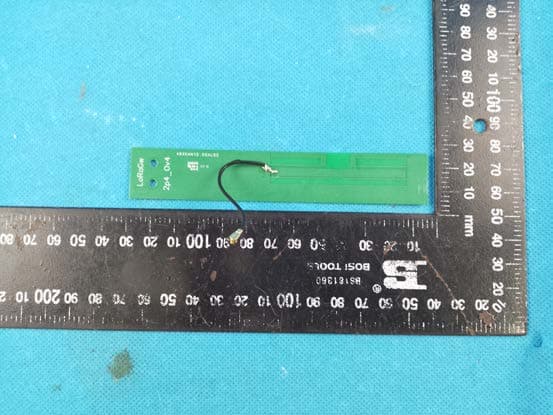
TV7LR2
May 16, 2023R11e-LR2
Equipment Class
DTS - Digital Transmission System