TV7LR2R11e-LR2
Mikrotikls SIA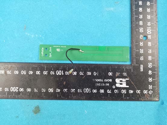
Click to zoom
Application Details
- Equipment Class
- DTS - Digital Transmission System
- Date of Grant
- May 16, 2023
- Application Purpose
- Original Equipment
- Date of Application
- May 16, 2023
- Equipment Note
- R11e-LR2
- Frequency Range
- 2403.00000000 - 2479.00000000
- Company
- Mikrotikls SIA
- Country
- Latvia
Documents & Files
Document Text
Text extracted from the exhibit documents filed with the FCC. Open a document above to read the original.
Users Manual
EN - English - Quick Guide: This "LR2 mini PCIe card" series Quick Guide covers models: R11e-LR2. This is a mini PCIe card. You can find the product model name on the label (ID). Please visit the user manual page on for the full up-to-date user manual. Or scan the QR code with your mobile phone. https://mt.lv/um Technical specifications, brochures, and more info about products at https://mikrotik.com/products Configuration manual for software in your language with additional information can be found at https://mt.lv/help MikroTik devices are for professional use. If you do not have qualifications please seek a consultant https://mikrotik.com/consultants First Use: This mini PCIe card is designed to be installed in the MikroTik host products. Compatible MikroTik host products can be found at https://mikrotik.com/products /group/iot-products For the initial configuration and installation guide see the specific MikroTik host product's User Manual. Safety Information: Before you work on any MikroTik equipment, be aware of the hazards involved with electrical circuitry, and be familiar with standard practices for preventing accidents. The installer should be familiar with network structures, terms, and concepts. The product comes without enclosure and is meant to be installed into the MikroTik host device by trained and qualified personnel. For mounting instructions see MikroTik Host Product's Quick Guide. The installer is responsible for making sure, that the Installation of the equipment is compliant with local the chosen and national electrical codes. Do not attempt to disassemble, repair, or modify the device. Please read the mounting instructions carefully before beginning installation. Failure to use the correct hardware and configuration or to follow the correct procedures could result in a hazardous situation for people and damage to the system. Keep this away from water, fire, humidity, or hot environments.mini PCIe card We cannot guarantee that no accidents or damage will occur due to the improper use of the device. Please use this product with care and operate at your own risk! This MikroTik equipment complies with the FCC, IC, and European Union radiation exposure limits set forth for anExposure to Radio Frequency Radiation: uncontrolled environment. This MikroTik device should be installed and operated no closer than 20 centimeters from your body, occupational user, or the general public. Manufacturer: Mikrotikls SIA, Brivibas gatve 214i Riga, Latvia, LV1039. Federal Communication Commission Interference Statement ModelFCC ID R11e-LR2TV7LR2 This equipment has been tested and found to comply with the limits for a Class B digital device, pursuant to Part 15 of the FCC Rules. These limits are designed to provide reasonable protection against harmful interference in a residential installation. This equipment generates, uses, and can radiate radio frequency energy and, if not installed and used in accordance with the instructions, may cause harmful interference to radio communications. However, there is no guarantee that interference will not occur in a particular installation. If this equipment does cause harmful interference to radio or television reception, which can be determined by turning the equipment off and on, the user is encouraged to try to correct the interference by one or more of the following measures: Reorient or relocate the receiving antenna. Increase the separation between the equipment and receiver. Connect the equipment into an outlet on a circuit different from that to which the receiver is connected. Consult the dealer or an experienced radio/TV technician for help. FCC Caution: Any changes or modifications not expressly approved by the party responsible for compliance could void the user’s authority to operate this equipment. This device complies with Part 15 of the FCC Rules. Operation is subject to the following two conditions: (1) This device may not cause harmful interference, and (2) this device must accept any interference received, including interference that may cause undesired operation. Note: This unit was tested with shielded cables on the peripheral devices. Shielded cables must be used with the unit to ensure compliance. This MikroTik equipment complies with the FCC and IC radiation exposure limits set forth for anExposure to Radio Frequency Radiation: uncontrolled environment. This MikroTik device should be installed and operated no closer than 20 centimeters from your body, occupational user, or the general public. OEM statement. This module is intended for OEM installations only. As such the OEM integrator is responsible for ensuring that the end-user has no manual instructions to remove install or modify the module. This module is limited to installations in mobile or fixed applications. OEM integrators may utilize antennas of an equal or lesser gain as appearing in the list in this document (reference 47 CFR, paragraph 15.204(c)(4) for further information on this topic. The MikroTik OEM RF Module complies with Part 15 of the FCC rules and regulations. OEM Modules have been certified by the FCC for use with other products without any further certification (as per FCC section 2.1091). Separate approval is required for other operating configurations including portable configurations with respect to 47CFR paragraph 2.1093 and different antenna configurations. The OEM is required to comply with all 47CFR labeling instructions and requirements for the finished products. Host product manufacturers that they need to provide a physical or e-label stating, “Contains FCC ID: TV7LR2” with their finished product. The chosen MikroTik host device for this mini PCIe card needs to be upgraded to RouterOS v7.3.1 or the latest version to ensure compliance with local authority regulations! It is the end users' responsibility to follow local country regulations, including operation within legal frequency channels, output power, cabling requirements, and Dynamic F…
Text truncated - open the document above for the full version.
Attestation Statements
Mikrotikls SIA (SIA "Mikrotīkls") Brand Name: MikroTik Address: Brivibas gatve 214i, Rīga, LV-1039, Latvia Phone: +371 67317700 Fax: +371 67317701 Email: [email protected] Covered Equipment Certification Attestation Letter Nemko North America, Inc. 303 River Road Ottawa K1V 1H2 Canada ATTN.: Reviewing Engineer FCC ID: TV7LR2 (Mikrotikls SIA ) certifies that the equipment for which authorization is sought is not “covered” equipment prohibited from receiving an equipment authorization pursuant to section 2.903 of the FCC rules. Note: If the equipment for which the applicant seeks authorization is produced by any of the entities identified on the current Covered List, the applicant should include an explanation on why the equipment is not “covered” equipment. (Mikrotikls SIA) certifies that, as of the date of the filing of the application, the applicant is not identified on the Covered List as an entity producing “covered” equipment. Signed: Printed name: Edmunds Zvegincevs Title: Compliance Engineer Company Name: Mikrotikls SIA Date:
Cover Letter(s)
Mikrotikls SIA (SIA "Mikrotīkls") Brand Name: MikroTik Address: Brivibas gatve 214i, Rīga, LV-1039, Latvia Phone: +371 67317700 Fax: +371 67317701 Email: [email protected] 2023-04-26 Nemko Canada Inc 303 River Road Ottawa, Ontario, Canada K1V 1H2 Attn: Director of Certification Authority to Act as Agent On our behalf, I appoint Shenzhen Huatongwei International Inspection Co., Ltd ./ 1/F, Bldg 3, Hongfa Hi-tech Industrial Park, Genyu Road, Tianliao, Gongming, Shenzhen, China / Hans Hu ,. to act as our agent in the preparation of this application for equipment certification. I certify that submitted documents properly describe the device or system for which equipment certification is sought. I also certify that each unit manufactured, imported or marketed, as defined in the Federal Communications Commission’s regulations will have affixed to it a label identical to that submitted for approval with this application. For instances where our authorized agent signs the application for certification on our behalf, I acknowledge that all responsibility for complying with the terms and conditions for certification, as specified by Nemko Canada Inc, still resides with Mikrotikls SIA / Brivibas gatve 214i, Riga, LV-1039, Latvia Agency agreement expiration date: 2024-04-25 By: Edmunds Zvegincevs Signature Printed On behalf of : Mikrotikls SIA Telephone: +371-6-7317700
Cover Letter(s)
Mikrotikls SIA (SIA "Mikrotīkls") Brand Name: MikroTik Address: Brivibas gatve 214i, Rīga, LV-1039, Latvia Phone: +371 67317700 Fax: +371 67317701 Email: [email protected] 2023-04-27 Equipment Autorisation Division Federal Communications Commission 7435 Oakland Mills Road Columbia, MD 21046 FCC ID: TV7LR2 Product Name: R11e-LR2 Request for Confidentiality Pursuant to Sections 0.457 and 0.459 of the commissions rules, we hereby request that the following documents be held confidential: Schematics Block diagram Operation description These materials contain trade secrets and proprietary information and are not customarily released to the public. The public disclosure of this information might be harmful to the company and provide unjustified benefits to our competitors. By: Edmunds Zvegincevs Signature Printed On behalf of : Mikrotikls SIA Telephone: +371-6-7317700
Cover Letter(s)
Mikrotikls SIA FCC Modular Approval Request Rev 2.1 Modular Transmitter Approval Request Federal Communications Commission Equipment Authorization Division 7435 Oakland Mills Road Columbia, MD 21046 USA Company name: Mikrotikls SIA FCC ID: TV7LR2 Dear Sir/Madam, In accordance with 47CFR 15.212 Modular Transmitters and KDB 996369 D01 ‘Module Equip Auth Guide v02’. FCC ID TV7LR2 has been examined against the following requirements. Requirement per 15.212 and KDB 996369 D01 Explanation from Grantee (do not write yes/no, but explain why product complies/how it is achieved) The radio elements must have the radio frequency circuitry shielded. Physical components and tuning capacitor(s) may be located external to the shield, but must be on the module assembly. Refer to external photos. This module does have shield cover total complies the requirement. The module must have buffered modulation/data inputs to ensure that the device will comply with Part 15 requirements with any type of input signal. All inputs to the modules are buffered logic or microprocessor inputs, total complies the requirement. Please refer to Schematics. The module must contain power supply regulation on the module. Complies the requirement, please refer to block diagram or Schematics. The module must contain a permanently attached antenna, or contain a unique antenna connector, and be marketed and operated only with specific antenna(s), per §§ 15.203, 15.204(b), 15.204(c), 15.212(a), 2.929(b). The antenna type is a non-standard antenna port, total complies the requirement,please refer to internal photos. The module must demonstrate compliance in a stand-alone configuration. Please refer to setup photos. The module must be labeled with its permanently affixed FCC ID label, or use an electronic display (see KDB Publication 784748). Refer to the label The module must comply with all specific rules applicable to the transmitter, including all the conditions provided in the integration instructions by the grantee. Refer to the user manual The module must comply with RF exposure requirements It’s complies, please refer to the MPE report and user manual Name: Edmunds Zvegincevs Date: 2023-04-26 Title: Compliance Engineer Signature of applicant:
External Photos
External Photos
Internal Photos
Internal Photos
RF Exposure Info
FCC ID: TV7LR2 RF Exposure Evaluation LIMIT The criteria listed in the following table shall be used to evaluate the environment impact of human exposure to radio frequency (RF) radiation as specified in 1.1307(b) Limits for Maximum Permissible Exposure (MPE) Frequency range (MHz) Electric field strength (V/m) Magnetic field strength (A/m) Power density (mW/cm 2 ) Averaging time (minutes) (A) Limits for Occupational/Controlled Exposures 0.3–3.0 614 1.63 *(100) 6 3.0–30 1842/f 4.89/f *(900/f 2 ) 6 30–300 61.4 0.163 1.0 6 300–1500 - - f/300 6 1500–100,000 - - 5 6 (B) Limits for General Population/Uncontrolled Exposure 0.3–1.34 614 1.63 *(100) 30 1.34–30 824/f 2.19/f *(180/f 2 ) 30 30–300 27.5 0.073 0.2 30 300–1500 - - f/1500 30 1500–100,000 - - 1.0 30 Note: f = frequency in MHz EVALUATION METHOD Transmission formula: Pd = (Pout*G)/(4*pi*r 2 ) Where Pd = power density in mW/cm 2 , Pout = output power to antenna in mW, G = gain of antenna in linear scale; Pi = 3.1416, R = distance between observation point and center of the radiator in cm TEST RESULT Passed Not Applicable Antenna Frequency range (MHz) Conducted Average Power (dBm) Maximum Tune-up (dBm) Power Density (mW/cm2) Limit (mW/cm2) Result PCB Antenna 2403-2479 10.81 11.00 0.0076 1.0000 Pass FRP Antenna 2403-2479 10.81 11.00 0.0194 1.0000 Pass Note: 1) The maximum antenna gain is PCB Antenna: 4.84 dBi, FRP Antenna: 8.8888dBi 2) The exposure evaluation safety distance is 20cm.
Test Report
Page: 1 of 36 TEST REPORT For 2.4G Report No. ...................................... : CHTEW23040043 Report Verification: Project No.................................: SHT2302030201EW FCC ID ............................................. : TV7LR2 Applicant’s name ........................... : Mikrotikls SIA Address ............................................. : Brivibas gatve 214i, Riga, LV-1039, Latvia Product Name ................................ : R11e-LR2 Trade Mark ....................................... : MikroTik Model No. ......................................... : R11e-LR2 Listed Model(s) ................................. : - Standard ......................................... : FCC CFR Title 47 Part 15 Subpart C § 15.247 Date of receipt of test sample..........: Mar.03, 2023 Date of testing.............................: Mar.03, 2023-Apr.11, 2023 Date of issue...............................: Apr.12, 2023 Result .................. ........................: PASS Compiled by ( Position+Printed name+Signature): File administrator Fanghui Zhu Supervised by (Position+Printed name+Signature): Project Engineer Kiki Kong Approved by (Position+Printed name+Signature): RF Manager Hans Hu Testing Laboratory Name ............. : Shenzhen Huatongwei International Inspection Co., Ltd. Address ............................................. : 1/F, Bldg 3, Hongfa Hi-tech Industrial Park, Genyu Road, Tianliao, Gongming, Shenzhen, China Shenzhen Huatongwei International Inspection Co., Ltd. All rights reserved. This publication may be reproduced in whole or in part for non-commercial purposes as long as the Shenzhen Huatongwei International Inspection Co., Ltd. is acknowledged as copyright owner and source of the material. Shenzhen Huatongwei International Inspection Co., Ltd. takes no responsibility for and will not assume liability for damages resulting from the reader's interpretation of the reproduced material due to its placement and context. The test report merely correspond to the test sample. Report No.: CHTEW23040043 Page: 2 of 36 Date of issue: 2023-04-12 Shenzhen Huatongwei International Inspection Co., Ltd. Report Template Version: V05(2023-0 3) Contents 1. TEST STANDARDS AND REPORT VERSION 3 1.1. Test Standards 3 1.2. Report version 3 2. TEST DESCRIPTION 4 3. SUMMARY 5 3.1. Client Information 5 3.2. Product Description 5 3.3. Radio Specification Description 5 3.4. Testing Laboratory Information 6 4. TEST CONFIGURATION 7 4.1. Test frequency list 7 4.2. Descriptions of Test mode 7 4.3. Test sample information 7 4.4. Support unit used in test configuration and system 8 4.5. Testing environmental condition 8 4.6. Statement of the measurement uncertainty 8 4.7. Equipment Used during the Test 9 5. TEST CONDITIONS AND RESULTS 10 5.1. Antenna Requirement 10 5.2. AC Conducted Emission 11 5.3. Peak Output Power 13 5.4. Power Spectral Density 14 5.5. 6dB bandwidth 15 5.6. 99% Occupied Bandwidth 16 5.7. Duty Cycle 17 5.8. Conducted Band edge and Spurious Emission 18 5.9. Radiated Band edge Emission 19 5.10. Radiated Spurious Emission 22 6. TEST SETUP PHOTOS 30 7. EXTERNAL AND INTERNAL PHOTOS 34 7.1. External Photos 34 7.2. Internal Photos 36 8. APPENDIX REPORT 36 Report No.: CHTEW23040043 Page: 3 of 36 Date of issue: 2023-04-12 Shenzhen Huatongwei International Inspection Co., Ltd. Report Template Version: V05(2023-0 3) 1. TEST STANDARDS AND REPORT VERSION 1.1. Test Standards The tests were performed according to following standards: ‒ FCC CFR Title 47 Part 15 Subpart C § 15.247: Operation within the bands 902-928 MHz, 2400-2483.5 MHz, and 5725-5850 MHz ‒ ANSI C63.10:2013: American National Standard for Testing Unlicensed Wireless Devices ‒ KDB 558074 D01 15.247 Meas Guidance v05r02: Guidance for Compliance Measurements on Digital Transmission System, Frequency Hopping Spread Spectrum System, and Hybrid System Devices Operating under Section 15.247 of The FCC Rules 1.2. Report version Revision No. Date of issue Description N/A 2023-04-12 Original Report No.: CHTEW23040043 Page: 4 of 36 Date of issue: 2023-04-12 Shenzhen Huatongwei International Inspection Co., Ltd. Report Template Version: V05(2023-0 3) 2. TEST DESCRIPTION Report clause Test Items Standard Requirement Result Test Engineer 5.1 Antenna Requirement 15.203/15.247(c) PASS Xiaoqin Li 5.2 AC Conducted Emission 15.207 PASS Yongjin Lin 5.3 Peak Output Power 15.247(b)(3) PASS Xiaoqin Li 5.4 Power Spectral Density 15.247(e) PASS Xiaoqin Li 5.5 6dB Bandwidth 15.247(a)(2) PASS Xiaoqin Li 5.6 99% Occupied Bandwidth - PASS *1 Xiaoqin Li 5.7 Duty cycle - PASS *1 Xiaoqin Li 5.8 Conducted Band Edge and Spurious Emission 15.247(d)/15.205 PASS Xiaoqin Li 5.9 Radiated Band Edge Emission 15.205/15.209 PASS Haoxin Luo 5.10 Radiated Spurious Emission 15.247(d)/15.205/15.209 PASS Quanhai Deng Note: ‒ The measurement uncertainty is not included in the test result. ‒ *1: No requirement on standard, only report these test data. Report No.: CHTEW23040043 Page: 5 of 36 Date of issue: 2023-04-12 Shenzhen Huatongwei International Inspection Co., Ltd. Report Template Version: V05(2023-0 3) 3. SUMMARY 3.1. Client Information Applicant: Mikrotikls SIA Address: Brivibas gatve 214i, Riga, LV-1039, Latvia Manufacturer: Mikrotikls SIA Address: Brivibas gatve 214i, Riga, LV-1039, Latvia 3.2. Product Description Main unit information: Product Name: R11e-LR2 Trade Mark: MikroTik Model No.: R11e-LR2 Listed Model(s): - Power supply: DC 24V from adapter Hardware version: r2r2 Software version: RouterOS v6 3.3. Radio Specification Description Operation frequency: 2403MHz, 2425MHz, 2450MHz, 2479MHz Channel number: 4 Modulation: Chirp Spread Spectrum Antenna type: PCB antenna or FRP antenna Antenna gain: PCB antenna: 4.84 dBi FRP antenna: 8.8888dBi Report No.: CHTEW23040043 Page: 6 of 36 Date of issue: 2023-04-12 Shenzhen Huatongwei International Inspection Co., Ltd. Report Template Version: V05(2023-0 3) 3.4. Testing Laboratory Information Laboratory Name Shenzhen Huatongwei Inte…
Text truncated - open the document above for the full version.
Test Report
Project No.: SHT2302030201EW Radio Specification: LORA Shenzhen Huatongwei International Inspection Co., Ltd. Appendix report page: 1 of 19 APPENDIX REPORT Project No. SHT2302030201EW Radio Specification LORA Test sample No. YPHT23020302001 Model No. R11e-LR2 Start test date 2023-04-06 Finish date 2023-04-06 Temperature 24.4°C Humidity 88% Test Engineer Xiaoqin Li Auditor Appendix clause Test item Result A Peak Output Power PASS B Power Spectral Density PASS C 6 dB Bandwidth PASS D 99% Occupied Bandwidth PASS E Duty cycle PASS F Band edge and Spurious Emissions (conducted) PASS Project No.: SHT2302030201EW Radio Specification: LORA Shenzhen Huatongwei International Inspection Co., Ltd. Appendix report page: 2 of 19 Appendix A:Peak Output Power Channel Peak Output power (dBm) Average Output power (dBm) Limit (dBm) Result CH L 10.82 10.81 ≤ 30.00 Pass CH M 10.73 10.69 CH H 10.50 10.44 CH H+1 9.97 9.91 Project No.: SHT2302030201EW Radio Specification: LORA Shenzhen Huatongwei International Inspection Co., Ltd. Appendix report page: 3 of 19 CH L Date: 6.APR.2023 10:27:48 CH M Date: 6.APR.2023 10:40:18 CH H Date: 6.APR.2023 10:36:31 Project No.: SHT2302030201EW Radio Specification: LORA Shenzhen Huatongwei International Inspection Co., Ltd. Appendix report page: 4 of 19 CH H+1 Date: 6.APR.2023 10:38:23 Project No.: SHT2302030201EW Radio Specification: LORA Shenzhen Huatongwei International Inspection Co., Ltd. Appendix report page: 5 of 19 Appendix B:Power Spectral Density Channel Power Spectral Density(dBm/3KHz) Limit (dBm/3KHz) Result CH L -8.54 ≤8.00 Pass CH M -8.57 CH H -8.77 CH H+1 -9.35 Project No.: SHT2302030201EW Radio Specification: LORA Shenzhen Huatongwei International Inspection Co., Ltd. Appendix report page: 6 of 19 CH L Date: 6.APR.2023 10:28:43 CH M Date: 6.APR.2023 10:40:50 CH H Date: 6.APR.2023 10:36:45 Project No.: SHT2302030201EW Radio Specification: LORA Shenzhen Huatongwei International Inspection Co., Ltd. Appendix report page: 7 of 19 CH H+1 Date: 6.APR.2023 10:38:37 Project No.: SHT2302030201EW Radio Specification: LORA Shenzhen Huatongwei International Inspection Co., Ltd. Appendix report page: 8 of 19 Appendix C:6dB bandwidth Channel 6dB Bandwidth(kHz) Limit (kHz) Result CH L 1685.00 ≥500 Pass CH M 1685.00 CH H 1685.00 CH H+1 1680.00 Project No.: SHT2302030201EW Radio Specification: LORA Shenzhen Huatongwei International Inspection Co., Ltd. Appendix report page: 9 of 19 CH L Date: 6.APR.2023 10:27:33 CH M Date: 6.APR.2023 10:40:03 CH H Date: 6.APR.2023 10:36:14 Project No.: SHT2302030201EW Radio Specification: LORA Shenzhen Huatongwei International Inspection Co., Ltd. Appendix report page: 10 of 19 CH H+1 Date: 6.APR.2023 10:38:07 Project No.: SHT2302030201EW Radio Specification: LORA Shenzhen Huatongwei International Inspection Co., Ltd. Appendix report page: 11 of 19 Appendix D:99% Occupied Bandwidth Channel 99% Occupied Bandwidth(MHz) Limit (kHz) Result CH L 1.69 - Pass CH M 1.69 CH H 1.69 CH H+1 1.69 Project No.: SHT2302030201EW Radio Specification: LORA Shenzhen Huatongwei International Inspection Co., Ltd. Appendix report page: 12 of 19 CH L Date: 6.APR.2023 10:27:40 CH M Date: 6.APR.2023 10:40:10 CH H Date: 6.APR.2023 10:36:22 Project No.: SHT2302030201EW Radio Specification: LORA Shenzhen Huatongwei International Inspection Co., Ltd. Appendix report page: 13 of 19 CH H+1 Date: 6.APR.2023 10:38:15 Project No.: SHT2302030201EW Radio Specification: LORA Shenzhen Huatongwei International Inspection Co., Ltd. Appendix report page: 14 of 19 Appendix E:Duty cycle Test Frequency (MHz) T on time for single burst (ms) T period (ms) Duty cycle 1/T on time (kHz) 2425 1 1 100% 1 Date: 6.APR.2023 10:35:34 Project No.: SHT2302030201EW Radio Specification: LORA Shenzhen Huatongwei International Inspection Co., Ltd. Appendix report page: 15 of 19 Appendix F:Band edge and Spurious Emissions (conducted) Test Item: Band edge CH L Date: 6.APR.2023 10:28:52 CH H Date: 6.APR.2023 10:38:46 Project No.: SHT2302030201EW Radio Specification: LORA Shenzhen Huatongwei International Inspection Co., Ltd. Appendix report page: 16 of 19 Test Item: SE CH L Reference level Date: 6.APR.2023 10:29:00 CH L 30MHz~1000MHz Date: 6.APR.2023 10:29:15 CH L 1GHz~26GHz Date: 6.APR.2023 10:29:30 Project No.: SHT2302030201EW Radio Specification: LORA Shenzhen Huatongwei International Inspection Co., Ltd. Appendix report page: 17 of 19 CH M Reference level Date: 6.APR.2023 10:40:55 CH M 30MHz~1000MHz Date: 6.APR.2023 10:41:10 CH M 1GHz~26GHz Date: 6.APR.2023 10:41:25 Project No.: SHT2302030201EW Radio Specification: LORA Shenzhen Huatongwei International Inspection Co., Ltd. Appendix report page: 18 of 19 CH H Reference level Date: 6.APR.2023 10:36:50 CH H 30MHz~1000MHz Date: 6.APR.2023 10:37:05 CH H 1GHz~26GHz Date: 6.APR.2023 10:37:21 Project No.: SHT2302030201EW Radio Specification: LORA Shenzhen Huatongwei International Inspection Co., Ltd. Appendix report page: 19 of 19 CH H+1 Reference level Date: 6.APR.2023 10:38:52 CH H+1 30MHz~1000MHz Date: 6.APR.2023 10:39:07 CH H+1 1GHz~26GHz Date: 6.APR.2023 10:39:22 --------End of Report--------
Test Report
Mikrotikls SIA (SIA "Mikrotīkls") Address: Brivibas gatve 214i, Rīga, LV-1039, Latvia Phone: +371 67317700 Fax: +371 67317701 Email: [email protected] Antenna details - R11e-LR2 Ant No. Number of Antennas TypeManufacturerModelFamilyPeak Gain (dBi)Dir BWFrequency Band (MHz) 11PCBMikroTik 95XKAN15.GAE PCB Omnidirectional 4.843602400-2483.5 21FRPMikroTikTOF-2400-8V-4 FRP Omnidirectional 8.88883602400-2483.5 Antenna Gain Testing Setup Explanation: Antenna testing is performed using the test setup above. Antenna gain is measured in 3d plane. The measurments are then taken and ran through CST studio Time domain solver sumulation system to draw Antenna peak gain diagram. Simulation is performed taking into account pcb with components, case desing, heatsink and etc. Realized antenna gain Diagram Antenna No. 1 Antenna No. 2
Test Setup Photos
TEST SETUP PHOTOS F RP antenna Radiated Emission AC Conducted Emission PCB antenna Radiated Emission AC Conducted Emission
Contact Information
Applicant
Edmunds Zvegincevs(Engineer, R&D)
Test Firm
Shenzhen Huatongwei International Inspection Co.,Tony Jiang
[email protected]+86-755-26748078
Technical Specifications
| # | Rule Parts | Frequency Range | Power Output |
|---|---|---|---|
| 1 | 15C | 2.40 GHz - 2.48 GHz | 12.08 mW |
Other Applications from Mikrotikls SIA
TV7A42BE52
Jul 16, 2026hAP be lite
Equipment Class
NII - Unlicensed National Information Infrastructure TXTV7MA53BE652
May 16, 2026MA53UG+HbeH
Equipment Class
6ID - 15E 6 GHz Low Power Indoor Access PointTV7-TGLR92
Feb 05, 2026TG-LR92
Equipment Class
DTS - Digital Transmission SystemTV7WAPGR52AX
Sep 03, 2024wAP ax
Equipment Class
JAB - Part 15 Class B Digital Device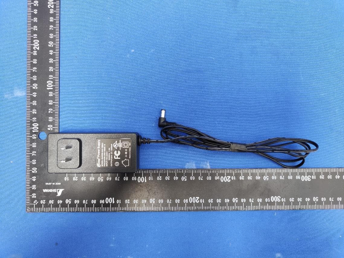
TV7CPG52X
Jan 10, 2023cAP ax
Equipment Class
NII - Unlicensed National Information Infrastructure TX