TV7C53-5AXD2AXDhAP ax3
Mikrotikls SIA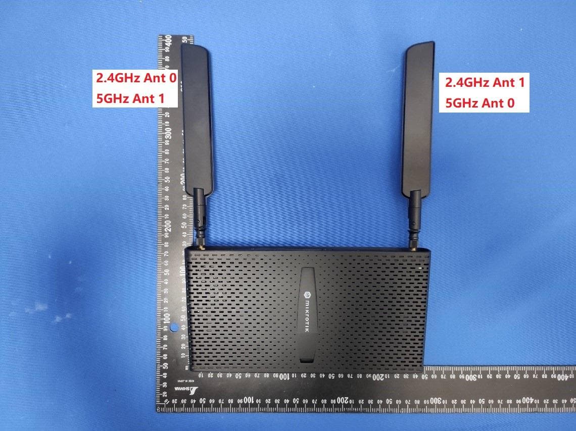
Click to zoom
Application Details
- Equipment Class
- NII - Unlicensed National Information Infrastructure TX
- Date of Grant
- Nov 08, 2022
- Application Purpose
- Original Equipment
- Date of Application
- Oct 13, 2022
- Equipment Note
- hAP ax3
- Frequency Range
- 5745.00000000 - 5825.00000000
- Company
- Mikrotikls SIA
- Country
- Latvia
Documents & Files
Document Text
Text extracted from the exhibit documents filed with the FCC. Open a document above to read the original.
Users Manual
1. 2. 3. 4. 5. 6. 7. 8. 9. 10. EN - English - Quick Guide: This "hAP ax³" series Quick Guide covers models: C53UiG+5HPaxD2HPaxD (hAP ax³). This is a wireless network device. You can find the product model name on the case label (ID). Please visit the user manual page on for the full up-to-date user manual. Or scan the QR code with your mobile phone. https://mt.lv/um The most relevant technical specifications for this product can be found on the last page of this Quick Guide. Technical specifications, brochures, and more info about products at https://mikrotik.com/products Configuration manual for software in your language with additional information can be found at https://mt.lv/help If you need help with configuration, please seek a consultant https://mikrotik.com/consultants First steps: Please attach provided antennas to the device, before connecting to the power source; Make sure your Internet service provider is allowing hardware change and will issue an automatic IP address; Connect the service provider cable to the Internet port and connect the device to the power source; Open network connections on your computer and search for MikroTik wireless network - connect to it; The configuration can be done through the wireless network using a web browser or mobile app. Alternatively, you can use a WinBox configuration tool htt ;ps://mt.lv/winbox Open in your web browser to start configuration, user name: a and there is no password by default https://192.168.88.1dmin(or, for some models, check user and wireless passwords on the sticker); Click the (Check for updates) button and update your RouterOS software to the latest version; Choose your country, to apply country regulation settings; Set up your wireless network password; Set up your router password; Safety Information: Before you work on any MikroTik equipment, be aware of the hazards involved with electrical circuitry, and be familiar with standard practices for preventing accidents. The installer should be familiar with network structures, terms, and concepts. Use only the power supply and accessories approved by the manufacturer, which can be found in the original packaging of this product. This equipment is to be installed by trained and qualified personnel, as per these installation instructions. The installer is responsible for making sure, that the Installation of the equipment is compliant with local and national electrical codes. Do not attempt to disassemble, repair, or modify the device. This product is intended to be installed indoors. Keep this product away from water, fire, humidity, or hot environments. We cannot guarantee that no accidents or damage will occur due to the improper use of the device. Please use this product with care and operate at your own risk! In the case of device failure, please disconnect it from power. The fastest way to do so is by unplugging the power adapter from the power outlet. This MikroTik equipment complies with the FCC, IC, and European Union radiation exposure limits set forth for anExposure to Radio Frequency Radiation: uncontrolled environment. This MikroTik device should be installed and operated no closer than 37 centimeters from your body, occupational user, or the general public. Manufacturer: Mikrotikls SIA, Brivibas gatve 214i Riga, Latvia, LV1039. BG - Български. Бързо ръководство: Това серия "hAP ax³" Бързо ръководство обхваща модели: C53UiG+5HPaxD2HPaxD (hAP ax³). Това е мрежово устройство. Можете да намерите името на модела на продукта на етикета на регистъра (ID). Моля, посетете страницата с ръководството за потребителя на за пълното актуализирано ръководство за употреба.https://mt.lv/um-bg Или сканирайте QR кода с мобилния си телефон. Най-важните технически спецификации за този продукт могат да бъдат намерени на последната страница на това Кратко ръководство. Технически спецификации, брошури и повече информация за продуктите на https://mikrotik.com/products Ръководство за конфигуриране на софтуер на вашия език с допълнителна информация можете да намерите наhttps://mt.lv/help-bg Ако имате нужда от помощ при конфигуриране, моля, потърсете консултант https://mikrotik.com/consultants Първи стъпки: This device needs to be upgraded to RouterOS v7.2.2 or the latest stable version, to ensure compliance with local authority regulations! It is the end users' responsibility to follow local country regulations, including operation within legal frequency channels, output power, cabling requirements, and Dynamic Frequency Selection (DFS) requirements. All MikroTik radio devices must be installed according to instructions. Това устройство трябва да бъде надстроено до RouterOS v7.2.2 или най-новата стабилна версия, за да се гарантира спазването на местните наредби! Крайните потребители са отговорни да спазват местните разпоредби, включително работа в рамките на законни честотни канали, изходна мощност, изисквания за окабеляване и изисквания за динамичен избор на честота (DFS). Всички радиоустройства MikroTik трябва да бъдат инсталирани съгласно инструкциите. Моля, прикрепете предоставените антени към устройството, преди да се свържете към източника на захранване; Уверете се, че вашият доставчик на интернет услуги позволява промяна на хардуера и ще издаде автоматичен IP адрес; Свържете устройството към източника на захранване; Отворете мрежовите връзки на вашия компютър и потърсете безжична мрежа MikroTik - свържете се към нея; Конфигурацията трябва да се извърши през безжичната мрежа с помощта на уеб браузър или мобилно приложение; Като алтернатива можете да използвате инструмент за конфигуриране на WinBox ;https://mt.lv/winbox отвореноhttps://192.168.88.1във вашия уеб браузър за стартиране на конфигурация, потребителско име: adminи няма парола по подразбиране (или, за някои модели, проверете потребителските и безжичните пароли на стикера); Когато използвате мобилно приложение, изберете Бърза настройка и то ще ви преведе през цялата необходима конфигурация в шест лесни стъпки; Щракнете в…
Text truncated - open the document above for the full version.
Attestation Statements
Mikrotikls SIA (SIA "Mikrotīkls") Address: Brivibas gatve 214i, Rīga, LV-1039, Latvia Phone: +371 67317700 Fax: +371 67317701 Email: [email protected] Declaration of Conformity Federal Communications Commission Authorization and Evaluation Division FCC ID: FCC ID: TV7C53-5AXD2AXD TV7C53-5AXD2AXD Please be notified that we, the undersigned, Mikrotikls SIA declares that the product which bears the above FCC ID is also compliant with the FCC requirements for sDOC. And the sDOC procedure shall be carried out prior to marketing the device in the US. Sincerely, _________________ Name: Edmunds Zvegincevs Title: Engineer, R&D Email: [email protected] Phone: +371 67317700 Date: 2022-09-19
Cover Letter(s)
Mikrotikls SIA (SIA "Mikrotīkls") Address: Brivibas gatve 214i, Rīga, LV-1039, Latvia Phone: +371 67317700 Fax: +371 67317701 Email: [email protected] Confidentiality Request Letter Federal Communications Commission Authorization and Evaluation Division FCC ID: TV7C53-5AXD2AXD Pursuant to Sections 0.457 and 0.459 of the Commission’s Rules, we hereby request confidential treatment of information accompanying this application as outlined below: 1.Block Diagram 2.Schematics 3.Operational Description The above materials contain trade secrets and proprietary information not customarily released to the public. The public disclosure of these matters might be harmful to the applicant and provide unjustified benefits to its competitors. The applicant understands that pursuant to Rule 0.457, disclosure of this application and all accompanying documentation will not be made before the date of the Grant for this application. Sincerely, _________________ Name: Edmunds Zvegincevs Title: Engineer, R&D Email: [email protected] Phone: +371 67317700 Date: 2022-09-19
Cover Letter(s)
Mikrotikls SIA (SIA "Mikrotīkls") Address: Brivibas gatve 214i, Rīga, LV-1039, Latvia Phone: +371 67317700 Fax: +371 67317701 Email: [email protected] Declaration of Authorization We Name: Mikrotikls SIA Address: Brivibas gatve 214i, Riga, LV-1039 LATVIA Declare that: Name Representative of agent:Marlin Chen Agent Company name:MRT Technology (Suzhou) Co., Ltd Address:D8 Building, Youxin Industrial Park, No.2 Tian'edang Rd., Wuzhong Economic Development Zone City:Suzhou Country:China is authorized to apply for Certification of the following product(s): Product:hAP ax 3 FCC ID:TV7C53-5AXD2AXD Model No.:C53UiG+5HPaxD2HPaxD-US Sincerely, ________________ Name: Edmunds Zvegincevs Title: Engineer, R&D Email: [email protected] Phone: +371 67317700 Date: 2022-09-19
External Photos
Report No.: 2207RSU013-UE 1 of 5 EUT External Photograph (1) EUT Photo (2) EUT Photo Report No.: 2207RSU013-UE 2 of 5 (3) EUT Photo (4) EUT Photo Report No.: 2207RSU013-UE 3 of 5 (5) EUT Photo (6) EUT Photo Report No.: 2207RSU013-UE 4 of 5 (7) EUT Photo (8) EUT Photo Report No.: 2207RSU013-UE 5 of 5 (9) EUT Photo
ID Label/Location Info
Label and its location hAP ax³ ID: C53UiG+5HPaxD2HPaxD FCC ID: TV7C53-5AXD2AXD IC: 7442A-C53AX E01: xxx W01: xxx SN : xxx hAP ax³ ID: C53UiG+5HPaxD2HPaxD-US FCC ID: TV7C53-5AXD2AXD IC: 7442A-C53AX E01: xxx W01: xxx SN : xxx 1. CE label 2. FCC/IC label Label Label
Internal Photos
Report No.: 2207RSU013-UE 1 of 11 EUT Internal Photograph (1) EUT Photo (2) EUT Photo Report No.: 2207RSU013-UE 2 of 11 (3) EUT Photo (4) EUT Photo Report No.: 2207RSU013-UE 3 of 11 (5) EUT Photo (6) EUT Photo Report No.: 2207RSU013-UE 4 of 11 (7) EUT Photo (8) EUT Photo Report No.: 2207RSU013-UE 5 of 11 (9) EUT Photo (10) EUT Photo Report No.: 2207RSU013-UE 6 of 11 (11) EUT Photo (12) EUT Photo Report No.: 2207RSU013-UE 7 of 11 (13) EUT Photo (14) EUT Photo Report No.: 2207RSU013-UE 8 of 11 (15) EUT Photo (16) EUT Photo Report No.: 2207RSU013-UE 9 of 11 (17) EUT Photo (18) EUT Photo Report No.: 2207RSU013-UE 10 of 11 (19) EUT Photo (20) EUT Photo Report No.: 2207RSU013-UE 11 of 11 (21) EUT Photo
RF Exposure Info
MRT Technology (Suzhou) Co., Ltd Report No.: 2207RSU013-U4 Phone: +86-512-66308358 Report Version: V02 Web: www.mrt-cert.com Issue Date: 2022-11-03 Template Version:0.0 1 of 8 RF Exposure Evaluation Declaration FCC ID: TV7C53-5AXD2AXD Applicant: Mikrotikls SIA Product: hAP ax 3 Model No.: C53UiG+5HPaxD2HPaxD-US Brand Name: MikroTik FCC Classification: Digital Transmission System (DTS) Unlicensed National Information Infrastructure (NII) FCC Rule Part(s): Part15 Subpart C (Section 15.247) Result: Complies Reviewed By: Vincent Yu Approved By: Robin Wu The test results relate only to the samples tested. The test results shown in the test report are traceable to the national/international standards through the calibration of the equipment and evaluated measurement uncertainty herein. The test report shall not be reproduced except in full without the written approval of MRT Technology (Suzhou) Co., Ltd. Report No.: 2207RSU013-U4 2 of 8 Revision History Report No. Version Description Issue Date Note 2207RSU013-U4 Rev. 01 Initial Report 2022-09-28 Invalid 2207RSU013-U4 Rev. 02 Update the antenna gain for NII-2C band in clause 1.5 and update the calculation results in clause 2.2 2022-11-03 Valid Report No.: 2207RSU013-U4 3 of 8 CONTENTS Description Page 1. General Information ................................................................................................................................ 4 1.1. Applicant ........................................................................................................................................ 4 1.2. Manufacturer ................................................................................................................................. 4 1.3. Testing Facility ............................................................................................................................... 4 1.4. Product Information ....................................................................................................................... 5 1.5. Antenna Details ............................................................................................................................. 5 1.6. Device Classification ..................................................................................................................... 6 2. RF Exposure Evaluation ......................................................................................................................... 7 2.1. Test Limits ..................................................................................................................................... 7 2.2. Test Result ..................................................................................................................................... 8 Report No.: 2207RSU013-U4 4 of 8 1. General Information 1.1. Applicant Mikrotikls SIA Brivibas gatve 214i, Riga, LV-1039 LATVIA 1.2. Manufacturer Mikrotikls SIA Brivibas gatve 214i, Riga, LV-1039 LATVIA 1.3. Testing Facility Test Site – MRT Suzhou Laboratory Laboratory Location (Suzhou - Wuzhong) D8 Building, No.2 Tian’edang Rd., Wuzhong Economic Development Zone, Suzhou, China Laboratory Location (Suzhou - SIP) 4b Building, Liando U Valley, No.200 Xingpu Rd., Shengpu Town, Suzhou Industrial Park, China Laboratory Accreditations A2LA: 3628.01 CNAS: L10551 FCC: CN1166 ISED: CN0001 VCCI: R-20025 G-20034 C-20020 T-20020 R-20141 G-20134 C-20103 T-20104 Test Site – MRT Shenzhen Laboratory Laboratory Location (Shenzhen) 1G, Building A, Junxiangda Building, Zhongshanyuan Road West, Nanshan District, Shenzhen, China Laboratory Accreditations A2LA: 3628.02 CNAS: L10551 FCC: CN1284 ISED: CN0105 Test Site – MRT Taiwan Laboratory Laboratory Location (Taiwan) No. 38, Fuxing 2nd Rd., Guishan Dist., Taoyuan City 333, Taiwan (R.O.C.) Laboratory Accreditations TAF: L3261-190725 FCC: 291082, TW3261 ISED: TW3261 Report No.: 2207RSU013-U4 5 of 8 1.4. Product Information Product Name hAP ax 3 Model No. C53UiG+5HPaxD2HPaxD-US Wi-Fi Specification 802.11a/b/g/n/ac/ax, VHT Hardware Version r3 Software Version RouterOS v7 Antenna Information Refer to section 1.7 Working Voltage Range 12~28VDC (24VDC Nominal) Working Temperature 0 ~ 70°C Accessory Adapter Model: SAW36-240-1500U Input: 100-240V ~ 50/60Hz, 1.3A Output: 24V, 1.5A Remark: The information of EUT was provided by the manufacturer, and the accuracy of the information shall be the responsibility of the manufacturer. 1.5. Antenna Details Antenna Type Frequency Band (MHz) Number of spatial streams Max Peak Gain (dBi) CDD Directional Gain (dBi) For Power For PSD Wi-Fi Antenna (2*2 MIMO) Dipole Antenna 2412 ~ 2462 1 3.3 3.3 6.31 5180 ~ 5240 1 5.5 5.5 8.51 5260 ~ 5320 5.5 5.5 8.51 5500 ~ 5720 6.0 6.0 9.01 5745 ~ 5825 5.5 5.5 8.51 Note: The EUT supports Cyclic Delay Diversity (CDD) mode, and CDD signals are correlated. For CDD transmissions, directional gain is calculated as follows, N ANT = 2, N SS = 1. If all antennas have the same gain, G ANT , Directional gain = G ANT + Array Gain, where Array Gain is as follows. • For power spectral density (PSD) measurements on all devices, Array Gain = 10 log (N ANT / N SS ) dB = 3.01; • For power measurements on IEEE 802.11 devices, Array Gain = 0 dB for N ANT ≤ 4; Report No.: 2207RSU013-U4 6 of 8 1.6. Device Classification According to the user manual, the antenna of this device is at least 37 cm away from the body of the user, this device is classified as a Mobile Device. So, the RF exposure evaluation requirements of § 2.1091 for mobile device exposure conditions subject to MPE limits. Report No.: 2207RSU013-U4 7 of 8 2. RF Exposure Evaluation 2.1. Test Limits According to FCC Part 2.1091, A mobile device is defined as a transmitting device designed to be used in other than fixed locations and to generally be used in such a way that a separation distance of at least 20 cm is normally maintained between the RF source's radiating structure(s) and the body of the user or nearby persons. According to …
Text truncated - open the document above for the full version.
Test Report
MAG.LAYERS APPROVAL SHEET CUSTOMER : 啟碁 CUSTOMER’S PART NO. : 08.22130.001 DESCRIPTION : RF ANTENNA ASSEMBLY PART NO. : EDA-2130-25GC4-A1 MT PID : 48995 DATE : AUTHORIZED BY : Alvin Chen FULLY APPROVED PARTIALLY APPROVED REJECTED SIGN SUGGESTION 美磊科技股份有限公司 MAG. LAYERS SCIENTIFIC-TECHNICS CO., LTD No.270, Nanfeng Rd., Pingzhen Dist., Taoyuan City 324, Taiwan (R.O.C.) TEL: +886-3-4159111 FAX: +886-3-4192255 http://www.maglayers.com.tw E-mail:[email protected] MAG.LAYERS Contents Item Description Page 1. ........ Antenna Specification ........3 2. ........ Test Report .......4~13 MAG.LAYERS Antenna Specification ■ ELECTRICAL PROPERTIES 1.1 Frequency Range ............ 2.4~2.5GHz/5.15~5.85GHz 1.2 Impedance ........................ 50 Ohm Nominal 1.3 Return Loss ...................... -4dB (Max) 1.4 VSWR ...................... 3.5(Max) 1.5 Radiation .......................... Omni-directional 1.6 Peak Gain ......................... 2.4~2.5GHz/3.36dBi 5.15~5.85GHz/6.01dBi 1.7 Efficiency........................... 2.4~2.5GHz/66% 5.15~5.85GHz/57% 1.8 Polarization ...................... Linear 1.9 Admitted Power ............... 1W ■ PHYSICAL PROPERTIES 2.1 Coaxial Cable ................................. Coaxial Cable Ø 1.37 (Black) 2.2 Connector ....................................... RP SMA Male 2.3 Operating Temp.......................... -20°C ~ +65°C 2.4 Storage Temp............................. -30°C ~ +75°C MAG.LAYERS Test Report ■ EXPERIMENTAL SETUP MAG.LAYERS ■ ELECTRICAL CHARACTERISTICS P/NO: EDA-2130-25GC4-A1 Spec: 2.4~2.5GHz/5.15~5.85GHz Return Loss VSWR MAG.LAYERS Frequency(MHz):2400~2500. Pattern Field:Z-X plane MAG.LAYERS Frequency(MHz):2400~2500. Pattern Field:Z-Y plane MAG.LAYERS Frequency(MHz):2400~2500. Pattern Field:X-Y plane MAG.LAYERS Frequency(MHz):5150~5850. Pattern Field:Z-X plane MAG.LAYERS Frequency(MHz):5150~5850. Pattern Field:Z-Y plane MAG.LAYERS Frequency(MHz):5150~5850. Pattern Field:X-Y plane MAG.LAYERS Peak Gain. 2G 5G MAG.LAYERS Efficiency 2G 5G
Test Report
MRT Technology (Suzhou) Co., Ltd Report No.: 2207RSU013-U3 Phone: +86-512-66308358 Report Version: V02 Web: www.mrt-cert.com Issue Date: 2022-11-03 Template Version:0.0 1 of 133 DFS MEASUREMENT REPORT FCC ID: TV7C53-5AXD2AXD Applicant: Mikrotikls SIA Product: hAP ax 3 Model No.: C53UiG+5HPaxD2HPaxD-US Brand Name: MikroTik FCC Classification: Unlicensed National Information Infrastructure (NII) FCC Rule Part(s): Part 15 Subpart E (Section 15.407) Result: Complies Test Date: 2022-07-22 ~ 2022-07-25 Reviewed By: Vincent Yu Approved By: Robin Wu The test results relate only to the samples tested. This equipment has been shown to be capable of compliance with the applicable technical standards as indicated in the measurement report and was tested in accordance with the measurement procedures specified in KDB 905462. Test results reported herein relate only to the item(s) tested. The test report shall not be reproduced except in full without the written approval of MRT Technology (Suzhou) Co., Ltd. Report No.: 2207RSU013-U3 2 of 133 Revision History Report No. Version Description Issue Date Note 2207RSU013-U3 Rev. 01 Initial Report 2022-09-28 Invalid 2207RSU013-U3 Rev. 02 Update the antenna gain for NII-2C band in clause 1.7 2022-11-03 Valid Report No.: 2207RSU013-U3 3 of 133 CONTENTS Description Page 1. General Information ................................................................................................................................ 5 1.1. Applicant ...................................................................................................................................... 5 1.2. Manufacturer ................................................................................................................................ 5 1.3. Testing Facility ............................................................................................................................. 5 1.4. Product Information ...................................................................................................................... 6 1.5. Radio Specification under Test .................................................................................................... 6 1.6. Working Frequencies ................................................................................................................... 7 1.7. Antenna Details ............................................................................................................................ 8 1.8. TPC Power ................................................................................................................................... 8 2. Test Configuration ................................................................................................................................... 9 2.1. Test Mode ..................................................................................................................................... 9 2.2. Test Channel ................................................................................................................................ 9 2.3. Applied Standards ........................................................................................................................ 9 2.4. Test Environment Condition ......................................................................................................... 9 3. DFS Detection Thresholds and Radar Test Waveforms .................................................................... 10 3.1. Applicability ................................................................................................................................ 10 3.2. DFS Devices Requirements........................................................................................................ 11 3.3. DFS Detection Threshold Values ............................................................................................... 13 3.4. Parameters of DFS Test Signals ................................................................................................ 14 3.5. Conducted Test Setup ................................................................................................................ 17 4. Measuring Instrument ........................................................................................................................... 18 5. Test Result .............................................................................................................................................. 19 5.1. Summary .................................................................................................................................... 19 5.2. Radar Waveform Calibration Measurement............................................................................... 20 5.2.1. Calibration Setup ....................................................................................................................... 20 5.2.2. Calibration Procedure ................................................................................................................ 20 5.2.3. Calibration & Channel Loading Result ....................................................................................... 20 5.3. NII Detection Bandwidth Measurement ..................................................................................... 21 5.3.1. Test Limit .................................................................................................................................... 21 5.3.2. Test Procedure ........................................................................................................................... 21 5.3.3. Test Result ................................................................................................................................. 22 5.4. Initial Channel Availability Check Time Measurement ............................................................... 23 5.4.1. Test Limit ...........................................…
Text truncated - open the document above for the full version.
Test Report
MRT Technology (Suzhou) Co., Ltd Report No.: 2207RSU013-U2 Phone: +86-512-66308358 Report Version: V02 Web: www.mrt-cert.com Issue Date: 2022-11-03 Template Version:0.0 1 of 300 RF MEASUREMENT REPORT FCC ID: TV7C53-5AXD2AXD Applicant: Mikrotikls SIA Product: hAP ax 3 Model No.: C53UiG+5HPaxD2HPaxD-US Brand Name: MikroTik FCC Classification: Unlicensed National Information Infrastructure (NII) FCC Rule Part(s): Part 15 Subpart E (Section 15.407) Result: Complies Test Date: 2022-07-19 ~ 2022-11-01 Reviewed By: Vincent Yu Approved By: Robin Wu The test results relate only to the samples tested. This equipment has been shown to be capable of compliance with the applicable technical standards as indicated in the measurement report and was tested in accordance with the measurement procedures specified in KDB789033. Test results reported herein relate only to the item(s) tested. The test report shall not be reproduced except in full without the written approval of MRT Technology (Suzhou) Co., Ltd. Report No.: 2207RSU013-U2 2 of 300 Revision History Report No. Version Description Issue Date Note 2207RSU013-U2 Rev. 01 Initial Report 2022-09-28 Invalid 2207RSU013-U2 Rev. 02 Update the antenna gain for NII-2C band in clause 1.7 and relevant necessary test data. 2022-11-03 Valid Report No.: 2207RSU013-U2 3 of 300 CONTENTS Description Page 1. General Information ................................................................................................................................ 6 1.1. Applicant ..................................................................................................................................... 6 1.2. Manufacturer............................................................................................................................... 6 1.3. Testing Facility ............................................................................................................................ 6 1.4. Product Information .................................................................................................................... 7 1.5. Radio Specification under Test ................................................................................................... 7 1.6. Working Frequencies .................................................................................................................. 8 1.7. Antenna Details .......................................................................................................................... 9 2. Test Configuration ................................................................................................................................. 10 2.1. Test Mode ................................................................................................................................. 10 2.2. Test System Connection Diagram ............................................................................................ 10 2.3. Test System Details ................................................................................................................... 11 2.4. Test Software ............................................................................................................................. 11 2.5. Applied Standards ..................................................................................................................... 11 2.6. Test Environment Condition ....................................................................................................... 11 3. Antenna Requirements ......................................................................................................................... 12 4. Measuring Instrument ........................................................................................................................... 13 5. Decision Rules and Measurement Uncertainty .................................................................................. 15 5.1. Decision Rules .......................................................................................................................... 15 5.2. Measurement Uncertainty ........................................................................................................ 15 6. Test Result .............................................................................................................................................. 16 6.1. Summary .................................................................................................................................. 16 6.2. 26dB & 99% Bandwidth Measurement ..................................................................................... 17 6.2.1. Test Limit ................................................................................................................................... 17 6.2.2. Test Procedure ......................................................................................................................... 17 6.2.3. Test Setting ............................................................................................................................... 17 6.2.4. Test Setup ................................................................................................................................. 17 6.2.5. Test Result ................................................................................................................................ 18 6.3. 6dB Bandwidth Measurement .................................................................................................. 19 6.3.1. Test Limit ................................................................................................................................... 19 6.3.2. Test Procedure ......................................................................................................................... 19 6.3.3. Test Setting ..................................................................................................................…
Text truncated - open the document above for the full version.
Test Report
Report No.: 2207RSU013-U2 53 of 300 802.11a 6dB Bandwidth Channel 149 (5745MHz) Channel 157 (5785MHz) Channel 165 (5825MHz) 802.11ac-VHT2…
Text truncated - open the document above for the full version.
Contact Information
Applicant
Edmunds Zvegincevs(Engineer, R&D)
Test Firm
MRT Technology (Suzhou) Co., Ltd.Mr. Marlin Chen
[email protected]8651266308358
Technical Specifications
| # | Rule Parts | Frequency Range | Power Output |
|---|---|---|---|
| 4 | 15E | 5.75 GHz - 5.83 GHz | 732.80 mW |
Other Applications from Mikrotikls SIA
TV7A42BE52
Jul 16, 2026hAP be lite
Equipment Class
NII - Unlicensed National Information Infrastructure TXTV7MA53BE652
May 16, 2026MA53UG+HbeH
Equipment Class
6ID - 15E 6 GHz Low Power Indoor Access PointTV7-TGLR92
Feb 05, 2026TG-LR92
Equipment Class
DTS - Digital Transmission SystemTV7WAPGR52AX
Sep 03, 2024wAP ax
Equipment Class
JAB - Part 15 Class B Digital Device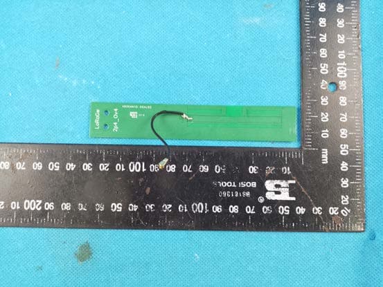
TV7LR2
May 16, 2023R11e-LR2
Equipment Class
DTS - Digital Transmission System