TV7D2352ACDigital Transmission System, Unlicensed National Information Infrastructure TX
Mikrotikls SIA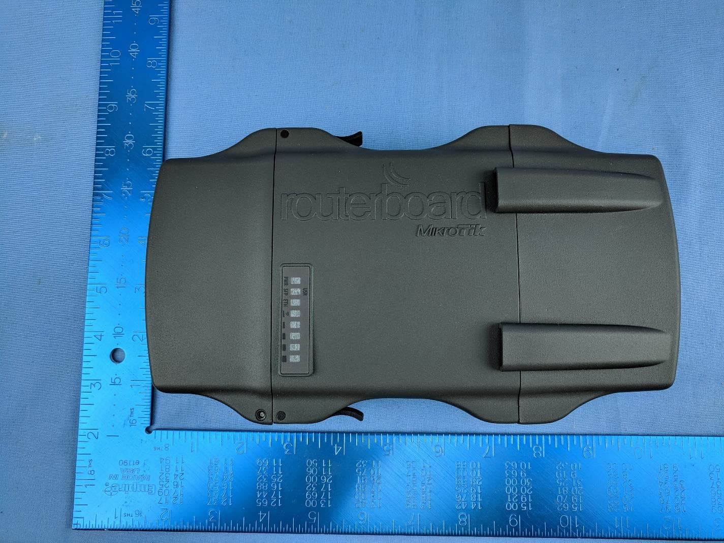
Click to zoom
Application Details
- Equipment Class
- NII - Unlicensed National Information Infrastructure TX
- Date of Grant
- Jan 22, 2020
- Application Purpose
- Original Equipment
- Date of Application
- Jan 22, 2020
- Equipment Note
- Digital Transmission System, Unlicensed National Information Infrastructure TX
- Frequency Range
- 5745.00000000 - 5825.00000000
- Company
- Mikrotikls SIA
- Country
- Latvia
Documents & Files
Document Text
Text extracted from the exhibit documents filed with the FCC. Open a document above to read the original.
Users Manual
NetMetal ac 2 Quickstart Please follow these quick steps to set up your device: •Open the upper cover (see “Removing upper and bottom covers”); •Connect an external antenna to the SMA connector (see “Antenna usage”); •Open the bottom cover (see “Removing upper and bottom covers”); •Connect the device to the power source (see “Powering”); •Open network connections on your PC, mobile phone or other device and search for MikroTik wireless network and connect to it; •The configuration can be done through the wireless network using a web browser or mobile app - (see “MikroTik mobile app”). Alternatively, you can use a WinBox configuration tool http://mt.lv/winbox; •Once connected to the wireless network, open http://192.168.88.1 in your web browser to start configuration, user name: admin and there is no password by default; •When using mobile application choose Quick setup and it will guide you through all necessary configuration in six easy steps; •Depending on the antenna used, you must set its gain in the RouterOS software to ensure that EIRP meets the limit set by the local authorities. This is done in the Wireless menu; •We recommend clicking the “Check for updates” button on the right side and updating your RouterOS software to the latest version to ensure the best performance and stability. •To personalize your wireless network, SSID can be changed in the fields “Network Name”; •Choose your country on the left side of the screen in the field “Country”, to apply country regulation settings. •Set up your wireless network password in the field “WiFi Password” the password must be at least eight symbols. •Set up your router password in the bottom field “Password” to the right and repeat it in the field “Confirm Password”, it will be used to login next time. •Click on the “Apply Configuration” to save changes. Powering The device accepts power in the following ways: •Ethernet port accepts PoE 802.3af/at 24-57 V DC ;⎓ •Direct-input power jack (5.5 mm outside and 2 mm inside, female, pin positive plug) accepts 12-57 V DC⎓. Connecting to a PoE Adapter: 1.Connect the Ethernet cable from the device to the PoE+DATA port of the PoE adapter; 2.Connect an Ethernet cable from your local network (LAN) to the PoE adapter; 3.Connect the power cord to the adapter, and then plug the power cord into a power outlet. MikroTik mobile app Use the MikroTik smartphone app to configure your router in the field, or to apply the most basic initial settings for your MikroTik home access point. 1.Scan QR code and choose your preferred OS. 2.Install and open application. 3.By default, the IP address and user name will be already entered. 4.Click Connect to establish a connection to your device through a wireless network. 5.Choose Quick setup and application will guide you through all basic configuration settings in a couple of easy steps. 6.An advanced menu is available to fully configure all necessary settings. See mikrotik.com/products for the latest version of this document. Page 1, Document #53381 Modified on: 30.JAN.2020 Removing upper and bottom covers 1.To remove the upper cover, unscrew two captive screws and slide it off the main body. Do not remove screws completely, when assembling tightening torque 0.2 Nm. 2.To remove the bottom cover, release clips for both fasteners and cover will be free to open. Mounting The NetMetal ac2 is designed to be used outdoors and mounted on pole or DIN rail. When mounting, please ensure that cable feed is pointing downwards. The IP rating scale of this device is IP55. We recommend using Cat6 shielded cables. Warning! This equipment should be installed and operated with a minimum distance of 20 cm between the device and your body. Operation of this equipment in the residential environment could cause radio interference. Mounting and configuration of this device should be done by a qualified person. The mounting hose clamp is provided with the package. 1.Guide hose clamp through the opening on the back of the device. 2.Attach to the pole or mast. 3.Align and secure by hose clamp screw using PH2 screwdriver. * The device should be always placed by TOP cover facing upwards. See mikrotik.com/products for the latest version of this document. Page 2, Document #53381 Modified on: 30.JAN.2020 •When mounting on DIN rail, please find special bracket in the package and secure it with four screws to the back of the unit. •With attached mounting bracket you will be able to slide the device on the DIN rail. Grounding The installation infrastructure (towers and masts), as well as the router itself, must be properly grounded. The device includes a grounding wire attachment screw. Attach your grounding wire to the grounding screw, then attach the other end of the grounding wire to the grounded mast. Please secure all loose Ethernet cables and antenna cables to the pole or mast approximately at 30cm from the device, so that the cable weight is not pulling the ports and connectors. Front status LED behavior RouterOS allows configuring each LEDs activity the way that user wishes. It is possible to configure the LEDs to display wireless strength, blink the LEDs on interface traffic activity and many other options. For further information please visit https://wiki.mikrotik.com/wiki/Manual:System/LEDS Default factory configuration for this device: 1.Solid Blue – The device is powered on. 2.Solid Green – Active SFP port. 3.Solid Green – Active Ethernet port. 4.- 8. Solid Green – The set of five green LEDs, shows the signal strength. See mikrotik.com/products for the latest version of this document. Page 3, Document #53381 Modified on: 30.JAN.2020 Configuration The device is configured as a wireless access point, with the Ethernet port configured as a DHCP client, for connecting to your ISP router or switch. A DHCP server is configured on the wireless interface. We recommend clicking the “Check for updates” button in the QuickSet menu, as updating your RouterOS software to the latest version ensures …
Text truncated - open the document above for the full version.
Attestation Statements
MikroTik (SIA "Mikrotīkls") Aizkraukles iela 23, Rīga, LV-1006, Latvia Phone: +371 67317700 FCC Software Configuration Control Declaration Date: December 30, 2019 Federal Communications Commission 7435 Oakland Mills Road Columbia, MD 21046 USA Attn: OET Dept. Product/ Model Number: RBD23UGS-5HPacD2HnD-NM-US Regarding FCC Country Code Selection guidelines identified in KDB 594280. “All applications for equipment authorization for transmitters that can have radio parameters, or other technical parameters, reported to the Commission set by software must have an attestation indicating that no third party will have software, or configuration control, to program the device out of compliance of the technical rules under which it has been certified.” We declare that no third party will have software, or configuration control, to program the device out of compliance of the technical rules under which it has been certified. Name: Edmunds ZveginzevsDate: December 30, 2019 Title:Compliance Engineer Signature of applicant
Attestation Statements
MikroTik (SIA "Mikrotīkls") VAT# LV40003286799 Billing addr.: Aizkraukles iela 23, Rīga, LV-1006, Latvia Office addr.: Brivibas gatve 214i, Riga, LV-1039, Latvia Phone: +371 67317700 Fax: +371 67317701 Date: 01.28.2020 To: Federal Communications Commission 7435 Oakland Mills Road Columbia, MD 21046, USA FCC ID: TV7D2352AC This letter is to attest that Mikrotikls SIA (MikroTik) Product RBD23UGS-5HPacD2HnD-NM-US (NetMetal ac²) has been tested and used for conducting FCC compliance testing. The SDoC portion has been conducted in accordance with FCC SDoC requirements as per Section 2.1077 compliance information. Suppliers Declaration of Conformity 47 CFR § 2.1077 Compliance Information Unique Identifier: RBD23UGS-5HPacD2HnD-NM-US Responsible party - Rogers Labs Inc. 4405 West 259th Terrace, Louisburg, KS 66053, USA [email protected] FCC Compliance Statement (Product is subject to CFR 47 Part 15 Subpart B – Unintentional Radiators) This device complies with Part 15 of the FCC Rules. Operation is subject to the following two conditions: (1) This device may not cause harmful interference, and (2) this device must accept any interference received, including interference that may cause undesired operation. In accordance with FCC SDoC requirement as per Section 2.1077 compliance information. Sincerely, Name / title : Scot Rogers / President Company: Rogers Labs, Inc. Address: 4405 West 259th Terrace, Louisburg, KS 66053 Email: [email protected] Date: January 28, 2020
Cover Letter(s)
SIA "Mikrotīkls" Aizkraukles iela 23, Rīga, LV-1006, Latvia Phone: +371 67317700 Fax: +371 67317701 Agent Authorization Company:Mikrotikls SIA Address:Brivibas gatve 214i, Riga, LV-1039 LATVIA Product Name:NetMetal ac² Short Name:RBD23UGS-5HPacD2HnD-NM-US We authorize MiCOM Labs, 575 Boulder Court, Pleasanton, CA 94566, USA, to act on our behalf on all matters concerning the above named equipment. We declare that MiCOM Labs, 575 Boulder Court, Pleasanton, CA 94566, USA, is allowed to forward all information related to the approval project to the applied notified body and to the notification entities and to discuss any issues concerning the approval application. Any and all acts carried out by MiCOM Labs on our behalf shall have the same effect as acts of our own. Name:Edmunds ZvegincevsDate: 30 December, 2019 Title:Engineer Signature of applicant:
Cover Letter(s)
MikroTik (SIA "Mikrotīkls") VAT# LV40003286799 Billing addr.: Aizkraukles iela 23, Rīga, LV-1006, Latvia Office addr.: Brivibas gatve 214i, Riga, LV-1039, Latvia Phone: +371 67317700 Fax: +371 67317701 Office of Engineering Technology Federal Communications Commission 7435 Oakland Mills Road Columbia, MD 21046 USA Date: December 30, 2019 Subject; Request for Confidentiality FCC ID: TV7D2352AC To Whom It May Concern, Pursuant to the provisions of the Commission’s rules Title 47 Sections §0.457 and §0.459, we are requesting the Commission to withhold the following attachment(s) as confidential documents from public disclosure indefinitely. These documents contain detailed system and equipment descriptions and are considered as proprietary information in operation of the equipment. The public disclosure of these documents might be harmful to our company and would give competitors an unfair advantage in the market. Schematic Diagram Block Diagram Parts List Operational Description Tune-up Procedure In additional to above mentioned documents, in order to comply with the marketing regulations in Title 47 CFR §2.803 and the importation rules in Title 47 CFR §2.1204, while ensuring that business sensitive information remains confidential until the actual marketing of newly authorized devices, we request Short Term Confidentiality of the following attachment(s); External Photos Test Setup Photos Internal Photos User Manual For 180 days pursuant to KDB 726920 D01. It is our understanding that all measurement test reports, FCC ID label format and correspondence during the certification review process cannot be granted as confidential documents and this information will be available for public review once the grant of equipment authorization is issued. Sincerely, Signature: Name: Edmunds Zvegincevs Title: Compliance Engineer
External Photos
PHOTOS - EXTERNAL Company: Mikrotikls SIA (MikroTik) Product Name: RBD23UGS-5HPacD2HnD-NM-US Report No.: MIKO95 – External Photos Title: MIKO95 FCC & IC External Photos To: Serial #: Issue Date: 21 November 2019 Page: 2 of 11 This test report may be reproduced in full only. The document may only be updated by MiCOM Labs personnel. All changes will be noted in the Document History section of the report. MiCOM Labs, 575 Boulder Court, Pleasanton, California 94566 USA, Phone: +1 (925) 462 0304, Fax: +1 (925) 462 0306, www.micomlabs.com 1. External Photographs 1.1.1. Product - External Front View Title: MIKO95 FCC & IC External Photos To: Serial #: Issue Date: 21 November 2019 Page: 3 of 11 This test report may be reproduced in full only. The document may only be updated by MiCOM Labs personnel. All changes will be noted in the Document History section of the report. MiCOM Labs, 575 Boulder Court, Pleasanton, California 94566 USA, Phone: +1 (925) 462 0304, Fax: +1 (925) 462 0306, www.micomlabs.com Antenna Ports Title: MIKO95 FCC & IC External Photos To: Serial #: Issue Date: 21 November 2019 Page: 4 of 11 This test report may be reproduced in full only. The document may only be updated by MiCOM Labs personnel. All changes will be noted in the Document History section of the report. MiCOM Labs, 575 Boulder Court, Pleasanton, California 94566 USA, Phone: +1 (925) 462 0304, Fax: +1 (925) 462 0306, www.micomlabs.com Back View Title: MIKO95 FCC & IC External Photos To: Serial #: Issue Date: 21 November 2019 Page: 5 of 11 This test report may be reproduced in full only. The document may only be updated by MiCOM Labs personnel. All changes will be noted in the Document History section of the report. MiCOM Labs, 575 Boulder Court, Pleasanton, California 94566 USA, Phone: +1 (925) 462 0304, Fax: +1 (925) 462 0306, www.micomlabs.com Bottom View Title: MIKO95 FCC & IC External Photos To: Serial #: Issue Date: 21 November 2019 Page: 6 of 11 This test report may be reproduced in full only. The document may only be updated by MiCOM Labs personnel. All changes will be noted in the Document History section of the report. MiCOM Labs, 575 Boulder Court, Pleasanton, California 94566 USA, Phone: +1 (925) 462 0304, Fax: +1 (925) 462 0306, www.micomlabs.com Label Title: MIKO95 FCC & IC External Photos To: Serial #: Issue Date: 21 November 2019 Page: 7 of 11 This test report may be reproduced in full only. The document may only be updated by MiCOM Labs personnel. All changes will be noted in the Document History section of the report. MiCOM Labs, 575 Boulder Court, Pleasanton, California 94566 USA, Phone: +1 (925) 462 0304, Fax: +1 (925) 462 0306, www.micomlabs.com Left View Title: MIKO95 FCC & IC External Photos To: Serial #: Issue Date: 21 November 2019 Page: 8 of 11 This test report may be reproduced in full only. The document may only be updated by MiCOM Labs personnel. All changes will be noted in the Document History section of the report. MiCOM Labs, 575 Boulder Court, Pleasanton, California 94566 USA, Phone: +1 (925) 462 0304, Fax: +1 (925) 462 0306, www.micomlabs.com Ports Title: MIKO95 FCC & IC External Photos To: Serial #: Issue Date: 21 November 2019 Page: 9 of 11 This test report may be reproduced in full only. The document may only be updated by MiCOM Labs personnel. All changes will be noted in the Document History section of the report. MiCOM Labs, 575 Boulder Court, Pleasanton, California 94566 USA, Phone: +1 (925) 462 0304, Fax: +1 (925) 462 0306, www.micomlabs.com Right View Title: MIKO95 FCC & IC External Photos To: Serial #: Issue Date: 21 November 2019 Page: 10 of 11 This test report may be reproduced in full only. The document may only be updated by MiCOM Labs personnel. All changes will be noted in the Document History section of the report. MiCOM Labs, 575 Boulder Court, Pleasanton, California 94566 USA, Phone: +1 (925) 462 0304, Fax: +1 (925) 462 0306, www.micomlabs.com Top View 575 Boulder Court Pleasanton, California 94566, USA Tel: +1 (925) 462 0304 Fax: +1 (925) 462 0306 www.micomlabs.com
ID Label/Location Info
NetMetal ac² Model: RBD23UGS-5HPacD2HnD-NM-US FCC ID:TV7D2352AC IC: 7442A-D2352AC SN: xxx
Internal Photos
PHOTOS - INTERNAL Company: Mikrotikls SIA (MikroTik) Product Name: RBD23UGS-5HPacD2HnD-NM-US Report No.: MIKO95 – Internal Photos Title: MIKO95 Internal Photos To: Serial #: Issue Date: 26 November 2019 Page: 2 of 5 This test report may be reproduced in full only. The document may only be updated by MiCOM Labs personnel. All changes will be noted in the Document History section of the report. MiCOM Labs, 575 Boulder Court, Pleasanton, California 94566 USA, Phone: +1 (925) 462 0304, Fax: +1 (925) 462 0306, www.micomlabs.com 1. Internal Photographs 1.1.1. Product - Internal Main Board Back Title: MIKO95 Internal Photos To: Serial #: Issue Date: 26 November 2019 Page: 3 of 5 This test report may be reproduced in full only. The document may only be updated by MiCOM Labs personnel. All changes will be noted in the Document History section of the report. MiCOM Labs, 575 Boulder Court, Pleasanton, California 94566 USA, Phone: +1 (925) 462 0304, Fax: +1 (925) 462 0306, www.micomlabs.com Main Board Front Title: MIKO95 Internal Photos To: Serial #: Issue Date: 26 November 2019 Page: 4 of 5 This test report may be reproduced in full only. The document may only be updated by MiCOM Labs personnel. All changes will be noted in the Document History section of the report. MiCOM Labs, 575 Boulder Court, Pleasanton, California 94566 USA, Phone: +1 (925) 462 0304, Fax: +1 (925) 462 0306, www.micomlabs.com Main Board no Shields 575 Boulder Court Pleasanton, California 94566, USA Tel: +1 (925) 462 0304 Fax: +1 (925) 462 0306 www.micomlabs.com
RF Exposure Info
MPE/RF EXPOSURE TEST REPORT FCC CFR 47 Part 1.1310 TEST REPORT: MIKO95_MPE_FCC Rev A Company: Mikrotikls SIA (MikroTik) Model: RBD23UGS-5HPacD2HnD-NM-US Marketing Name: NetMetal ac² MPE/RF EXPOSURE TEST REPORT Company: Mikrotikls SIA (MikroTik) Model: RBD23UGS-5HPacD2HnD-NM-US To: FCC CFR 47 Part 1.1310 Test Report Serial No.: MIKO95 Rev A MPE This report supersedes: NONE Applicant: Mikrotikls SIA (MikroTik) Brivibas gatve 214i Riga, LV-1039 Latvia Issue Date: 19 th December 2019 This Test Report is Issued Under the Authority of: MiCOM Labs, Inc. 575 Boulder Court Pleasanton California 94566 USA Phone: +1 (925) 462-0304 Fax: +1 (925) 462-0306 www.micomlabs.com MiCOM Labs is an ISO 17025 Accredited Testing Laboratory Title: Mikrotikls SIA (MikroTik) To: FCC CFR 47 Part 1.1310 Serial #: MIKO95_MPE_FCC Rev A Issue Date: 19 th December 2019 Page: 3 of 4 This test report may be reproduced in full only. The document may only be updated by MiCOM Labs personnel. All changes will be noted in the Document History section of the report. MiCOM Labs, 575 Boulder Court, Pleasanton, California 94566 USA, Phone: +1 (925) 462 0304, Fax: +1 (925) 462 0306, www.micomlabs.com 1. MAXIMUM PERMISSABLE EXPOSURE Calculations for Maximum Permissible Exposure Levels Power Density = Pd (mW/cm 2 ) = EIRP/(4*π*d 2 ) EIRP = P * G P = Peak output power (mW) G = Antenna numeric gain (numeric) d = Separation distance (cm) Numeric Gain = 10 ^ (G (dBi)/10) The calculations in the table below use the highest conducted power values together with the lowest antenna gain specified for the EUT. These calculations represent worst case in terms of the exposure levels. Freq. Band (MHz) Ant Gain (dBi) Numeric Gain (numeric) Peak Output Power (dBm) Peak Output Power (mW) Calculated Power Density (mW/cm 2 ) @ 20cm Power Density Limit (mW/cm 2 ) Min Calculated safe distance for Limit (cm) Calculated Power Density (mW/cm 2 ) @ Safe Distance 2400.0 - 2483.5 5.00 3.16 24.25 266.25 0.17 1.00 9.00 1.00 5150.0 - 5250.0 19.00 79.43 16.80 47.82 0.76 1.00 18.00 1.00 5725.0 - 5850.0 19.00 79.43 16.74 47.16 0.75 1.00 18.00 1.00 Note: for mobile or fixed location transmitters the minimum separation distance is 20cm, even if calculations indicate the MPE distance to be less. Specification - Maximum Permissible Exposure Limits The Limit is defined in Table 1 of FCC §1.1310. 575 Boulder Court Pleasanton, California 94566, USA Tel: +1 (925) 462 0304 Fax: +1 (925) 462 0306 www.micomlabs.com
Test Report
REGULATORY COMPLIANCE TEST REPORT FCC CFR 47 15.407 Report No.: MIKO95-U4 Rev A Company: Mikrotikls SIA (MikroTik) Model: RBD23UGS-5HPacD2HnD-NM-US Marketing Name: NetMetal ac² REGULATORY COMPLIANCE TEST REPORT Company: Mikrotikls SIA (MikroTik) Model: RBD23UGS-5HPacD2HnD-NM-US To: FCC CFR 47 Part 15 Subpart E 15.407 Test Report Serial No.: MIKO95-U4 Rev A This report supersedes: NONE Applicant: Mikrotikls SIA (MikroTik) Brivibas gatve 214i Riga, LV-1039 Latvia Issue Date: 19 th December 2019 This Test Report is Issued Under the Authority of: MiCOM Labs, Inc. 575 Boulder Court Pleasanton California 94566 USA Phone: +1 (925) 462-0304 Fax: +1 (925) 462-0306 www.micomlabs.com MiCOM Labs is an ISO 17025 Accredited Testing Laboratory Title: Mikrotikls SIA (MikroTik) RBD23UGS- 5HPacD2HnD-NM-US To: FCC CFR 47 Part 15 Subpart E 15.407 Serial #: MIKO95-U4 Rev A Issue Date: 19 th December 2019 Page: 3 of 233 This test report may be reproduced in full only. The document may only be updated by MiCOM Labs personnel. All changes will be noted in the Document History section of the report. MiCOM Labs, 575 Boulder Court, Pleasanton, California 94566 USA, Phone: +1 (925) 462 0304, Fax: +1 (925) 462 0306, www.micomlabs.com Table of Contents 1. ACCREDITATION, LISTINGS & RECOGNITION ................................................................................ 4 1.1. TESTING ACCREDITATION ........................................................................................................ 4 1.2. RECOGNITION ............................................................................................................................. 5 1.3. PRODUCT CERTIFICATION ........................................................................................................ 6 2. DOCUMENT HISTORY ......................................................................................................................... 7 3. TEST RESULT CERTIFICATE ............................................................................................................. 8 4. REFERENCES AND MEASUREMENT UNCERTAINTY ..................................................................... 9 4.1. Normative References .................................................................................................................. 9 4.2. Test and Uncertainty Procedure ................................................................................................. 10 5. PRODUCT DETAILS AND TEST CONFIGURATIONS ..................................................................... 11 5.1. Technical Details ......................................................................................................................... 11 5.2. Scope Of Test Program .............................................................................................................. 12 5.3. Equipment Model(s) and Serial Number(s) ................................................................................. 13 5.4. Antenna Details ........................................................................................................................... 13 5.5. Cabling and I/O Ports .................................................................................................................. 13 5.6. Test Configurations ..................................................................................................................... 14 5.7. Equipment Modifications ............................................................................................................. 14 5.8. Deviations from the Test Standard ............................................................................................. 14 6. TEST SUMMARY ................................................................................................................................ 15 7. TEST EQUIPMENT CONFIGURATION(S) ......................................................................................... 16 7.1. RF Conducted Testing ................................................................................................................ 16 7.2. Radiated Emissions - 3m Chamber ............................................................................................ 18 7.3. ac Wireline ................................................................................................................................... 20 8. MEASUREMENT AND PRESENTATION OF TEST DATA ............................................................... 22 9. TEST RESULTS .................................................................................................................................. 23 9.1. Peak Transmit Power .................................................................................................................. 23 9.2. 26 dB & 99% Bandwidth ............................................................................................................. 33 9.3. 6 dB & 99% Bandwidth ............................................................................................................... 38 9.4. Power Spectral Density ............................................................................................................... 43 9.5. Radiated ...................................................................................................................................... 53 9.5.1. TX Spurious & Restricted Band Emissions .......................................................................... 56 9.5.2. Restricted Edge & Band-Edge Emissions ............................................................................ 68 9.5.3. Digital Emissions .................................................................................................................. 94 9.6. AC Wireline ................................................................................................................................. 97 A. APPENDIX - GRAPHICAL IMAGES .................................…
Text truncated - open the document above for the full version.
Test Setup Photos
PHOTOS - TEST SETUP Company: Mikrotikls SIA (MikroTik) Product Name: RBD23UGS-5HPacD2HnD-NM-US Report No.: MIKO95 – FCC & IC Test Setup Photos Title: MIKO95 FCC & IC Test Setup Photos To: Serial #: Issue Date: 21 November 2019 Page: 2 of 5 This test report may be reproduced in full only. The document may only be updated by MiCOM Labs personnel. All changes will be noted in the Document History section of the report. MiCOM Labs, 575 Boulder Court, Pleasanton, California 94566 USA, Phone: +1 (925) 462 0304, Fax: +1 (925) 462 0306, www.micomlabs.com 1. Test Setup Photographs 1.1.1. Test Setup - RE#1 - Radiated Emissions - 3m Chamber DA-2450-05RP-SMA-01 Spurious Emissions Digital Emissions with ACDC Adapter Title: MIKO95 FCC & IC Test Setup Photos To: Serial #: Issue Date: 21 November 2019 Page: 3 of 5 This test report may be reproduced in full only. The document may only be updated by MiCOM Labs personnel. All changes will be noted in the Document History section of the report. MiCOM Labs, 575 Boulder Court, Pleasanton, California 94566 USA, Phone: +1 (925) 462 0304, Fax: +1 (925) 462 0306, www.micomlabs.com Digital Emissions with POE MTAD-5G-30D3 Spurious Emissions Title: MIKO95 FCC & IC Test Setup Photos To: Serial #: Issue Date: 21 November 2019 Page: 4 of 5 This test report may be reproduced in full only. The document may only be updated by MiCOM Labs personnel. All changes will be noted in the Document History section of the report. MiCOM Labs, 575 Boulder Court, Pleasanton, California 94566 USA, Phone: +1 (925) 462 0304, Fax: +1 (925) 462 0306, www.micomlabs.com MTAS-5G-19D120 Spurious Emissions 1.1.2. Test Setup - RF#1 - Conducted Conducted RF 575 Boulder Court Pleasanton, California 94566, USA Tel: +1 (925) 462 0304 Fax: +1 (925) 462 0306 www.micomlabs.com
Contact Information
Applicant
Edmunds Zvegincevs(engineer, R&D)
Test Firm
MiCOM LabsGordon Hurst
Technical Specifications
| # | Rule Parts | Frequency Range | Power Output |
|---|---|---|---|
| 2 | 15E | 5.75 GHz - 5.83 GHz | 48.00 mW |
Other Applications from Mikrotikls SIA
TV7A42BE52
Jul 16, 2026hAP be lite
Equipment Class
NII - Unlicensed National Information Infrastructure TXTV7MA53BE652
May 16, 2026MA53UG+HbeH
Equipment Class
6ID - 15E 6 GHz Low Power Indoor Access PointTV7-TGLR92
Feb 05, 2026TG-LR92
Equipment Class
DTS - Digital Transmission SystemTV7WAPGR52AX
Sep 03, 2024wAP ax
Equipment Class
JAB - Part 15 Class B Digital Device
TV7LR2
May 16, 2023R11e-LR2
Equipment Class
DTS - Digital Transmission System