TV7R11E2HPNDDIGITAL TRANSMISSION SYSTEM MODULE
Mikrotikls SIA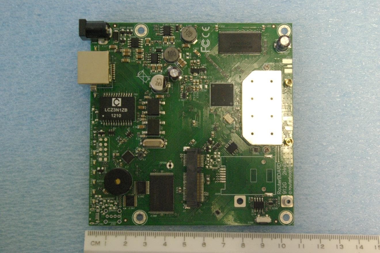
Click to zoom
Application Details
- Equipment Class
- DTS - Digital Transmission System
- Date of Grant
- Feb 25, 2014
- Application Purpose
- Original Equipment
- Date of Application
- Feb 11, 2014
- Equipment Note
- DIGITAL TRANSMISSION SYSTEM MODULE
- Frequency Range
- 2422.00000000 - 2452.00000000
- Company
- Mikrotikls SIA
- Country
- Latvia
Documents & Files
Document Text
Text extracted from the exhibit documents filed with the FCC. Open a document above to read the original.
Users Manual
Federal Communication Commission Interference Statement (FCC ID: TV7R11E2HPND) This equipment has been tested and found to comply with the limits for a Class B digital device, pursuant to Part 15 of the FCC Rules. These limits are designed to provide reasonable protection against harmful interference in a residential installation. This equipment generates uses and can radiate radio frequency energy and, if not installed and used in accordance with the instructions, may cause harmful interference to radio communications. However, there is no guarantee that interference will not occur in a particular installation. If this equipment does cause harmful interference to radio or television reception, which can be determined by turning the equipment off and on, the user is encouraged to try to correct the interference by one of the following measures: ● Reorient or relocate the receiving antenna. ● Increase the separation between the equipment and receiver. ● Connect the equipment into an outlet on a circuit different from that to which the receiver is connected. ● Consult the dealer or an experienced radio/TV technician for help. IMPORTANT: Exposure to Radio Frequency Radiation. The maximum permissible exposure report has been created for this module, which shows the minimum distances for public use as 142 cm when using a 24-dBi gain antenna. Under such configuration, the FCC radiation exposure limits set forth for a general population/uncontrolled environment can be satisfied. OEM statement. This module is intended for OEM installations only. As such the OEM integrator is responsible for ensuring that the end-user has no manual instructions to remove install or modify the module. This module is limited to installations in mobile or fixed applications. OEM integrators may utilize antennas of like an equal or lesser gain as appearing in the table below (for further infomraiton on this topic refer to 47CFR, paragraph 15.204(c)(4)). The MikroTik OEM RF Module complies with Part 15 of the FCC rules and regulations. OEM Modules have been certified by the FCC for use with other products without any further certification (as per 47CFR section 2.1091). Separate approval is required for other operating configurations including portable configurations with respect to 47CFR paragraph 2.1093 and different antenna configurations. The OEM is required to comply with all 47CFR labeling instructions and requirements for the finished products. Changes or modifications not expressly approved by MikroTik could void the OEM authority to install or operate the equipment. OEMs must test their final product to comply with unintentional radiators (47CFR section 15.107 and 15.109) before declaring compliance of their final product to Part 15 of the FCC Rules. Warning: the OEM must ensure that the end product complies with FCC labeling requirements. This includes a clearly visible label on the outside of the OEM enclosure specifying the appropriate MikroTik OEM RF Module FCC identifier for this product as well as any other required FCC notices as presented below. Contains FCC ID: TV7R11E2HPND This enclosed device complies with 47CFR paragraph 15 C of the FCC rules and regulations. Operation is subject to the following two conditions: (1) this device may not cause harmful interference, and (2) this device must accept any interference received, including interference that may cause undesired operation. Labeling and text information should be of a size of type large enough to be readily legible, consistent with the dimensions of the equipment and the label. FCC Caution: Any changes or modifications not expressly approved by the party responsible for compliance could void the user’s authority to operate this equipment. This device complies with Part 15 of the FCC Rules. Operation is subject to the following two conditions: (1) This device may not cause harmful interference, and (2) this device must accept any interference received, including interference that may cause undesired operation. This device and its antenna must not be co-located or operation in conjunction with any other antenna or transmitter. Warning: This device has been tested with a MMCX connector and antennas as listed in the table above. When integrated into the OEM products, these fixed antennas require professional installation preventing end users from replacing them with non-compliant antennas. List of approved antennas: Omni Directional, WLO-2450-15, 15 dBi; Omni Directional HP, ODH 24-13, 13dBi; Panel, WLP-2450-20, 20 dBi; Sector, SA-24-90-17-WB, 17 dBi; Dish, DC 24-HD-PFIP, 24 dBi; Antennas of same type and lower gain than those listed above may be used in compliance with certification. Antenna Installation Warning: It is installer's responsibility to ensure that only those antennas certified with the product are used for operation in the United States (or where FCC rules apply). The use of any antenna other than those certified with the product is expressly forbidden in accordance to FCC rules CFR47 paragraph 15.204. It is the installers’ responsibility to configure the output power level according to country regulations and antenna type. Professional installation is required of equipment with connectors to ensure compliance with health and safety issues. Antenna Model Gain (dBi) Maximum Transmit Power Per Chain Total (dBm) Omni Directional WLO-2450-15 15 24 27 Omni Directional HP ODH 24-13 13 24 27 Panel WLP-2450-20 20 22 25 Sector SA 24-90-17-WB 17 23 26 Dish DC 24-HD-PFIP 24 21 24
Cover Letter(s)
February 5, 2014 Timco Engineering Inc. 849 NW State Road 45 Newberry, FL 32669 Office of Engineering and Technology Federal Communications Commission Columbia, MD 21046 Applicant: Mikrotikls SIA Pernavas 46 Riga, Latvia LV-1009 Re: Confidentiality for submittal information regarding FCC ID number TV7R11E2HPND PRODUCT: Broadband Digital Transmission System Module operating under CFR47 part 15.247 Dear Sirs: Mikrotikls SIA requests that the material in the Parts List, Schematics, Block Diagram, and Operational Description be withheld from public disclosure pursuant to Sections 0.457 and 0.459 of the Commission’s Rules following grant of the application. In support of this request, Mikrotikls submits the following: Long Term Confidential Files Include Schematics File Name Conf Schem R11E2HPND.pdf Block diagram File Name Conf BlkDia R11E2HPND.pdf Operational Description File Name Conf OpDes R11E2HPND.pdf 1. Identification of the specific information for which confidential treatment is sought: The materials set forth in the Operational Description, block diagram, and Schematics, which are segregated from the non-confidential exhibits of the application, are those for which confidentiality is sought. 2. Identification of the Commission proceeding in which the information was submitted or a description of the circumstances giving rise to the submission: The proceeding is that involving the application for equipment authorization (certification) under FCC ID No: TV7R11E2HPND 3. Explanation of the degree to which the information is commercial or financial, or contains a trade secret or is privileged: This material includes a detailed theory of operation, circuit diagrams, (schematic diagrams) and any detail Parts List. As such, this material is treated as highly confidential business information. ROGERS LABS, INC. 4405 West 259 th Terrace Louisburg, KS 66053 4. Explanation of the degree to which the information concerns a service that is subject to competition: The material for which confidentiality is sought is employed in the design and manufacture of this transmitting equipment that is offered on a highly competitive basis. Customers for this equipment have a variety of competing sources. 5. Explanation of how disclosure of the information could result in substantial competitive harm: Disclosure would, in effect, give away the fruits of the labors of Mikrotikls SIA engineering personnel, who have designed the equipment and the manufacturing process. Disclosure would also offer competitors additional unwarranted insight into the state of the product development, thereby allowing competitors an advantage, not available to Mikrotikls SIA. 6. Identification of any measures taken by the submitting party to prevent unauthorized disclosure: The information for which confidential treatment is sought is kept confidential by Mikrotikls SIA and not made available to third parties except pursuant to non-disclosure agreements. 7. Identification of whether the information is available to the public and the extent of any previous disclosure of the information to third parties: To the knowledge of those preparing this application, the information has not been disclosed publicly heretofore. While the general theory of operation of this equipment has been the subject of numerous disclosures in industry and standards groups as well as in rule making proceedings of the FCC, the protection sought is narrowly drawn and pertains to certain specific implementations of this radio technology. 8. Justification of the period during which the submitting party asserts that the material should not be available for public disclosure: This material should not be disclosed for at least 25 years. While improvements in design are made relatively frequently, disclosure of the design information would lead to insights into both design and manufacturing techniques that could have an adverse competitive effect for many years to come. As such, it is important that the design not be made available to unauthorized persons who might attempt to use knowledge of the design to compromise the applications for which the equipment will be employed. Should you require any further information, please contact the undersigned. Thank you for your consideration in this matter. Sincerely, Scot Rogers
Cover Letter(s)
Date: February 3, 2014 Federal Communications Commission Equipment Approval Services P.O. Box 35815 Pittsburgh, PA 15251-3315 Applicant: MikroTik Ltd., Aizkraukles street 23 Pernavas street 46 Latvia Equipment: RouterBOARD R11e-2HnD FCC ID: TV7R11E2HPND CFR Rules: 15.247 (Modular Transmitter) Re: Modular transmitter approval Gentlemen: As required in CFR 47 15.212 regarding unlicensed modular transmitter approval, the following information has been addressed. The transmitter module is a complete RF transmitter containing its own reference oscillator, antenna etc. The connections available on the module are for power and data interface only. Below please find information, addressing each requirement from CFR 47 15.212. SIA "Mikrotīkls" VAT # LV40003286799 Billing addr.: Aizkraukles iela 23, LV-1006, Rīga Office addr.: Pērnavas iela 46, LV-1009, Rīga Phone: +371 67317700 Fax: +371 67317701 Bank account: A/S Nord/LB Latvija, Code RIKOLV2X, Account # LV33RIKO000201 0078616 Per CFR 47 15.212 (i) The radio elements of the modular transmitter must have their own shielding. The physical crystal and tuning capacitors may be located external to the shielded radio elements. Clarification: The RouterBOARD R11e-2HnD is produced with permanently attached RF shield during production. (ii) The modular transmitter must have buffered modulation/data inputs (if such inputs are provided) to ensure that the module will comply with part 15 requirements under conditions of excessive data rates or over-modulation. Clarification: The RouterBOARD R11e-2HnD buffers the modulation and data inputs ensuring compliance with regulations. (iii) The modular transmitter must have its own power supply regulation. Clarification: The RouterBOARD R11e-2HnD incorporates regulators to ensure operation in specified range. (iv) The modular transmitter must comply with the antenna and transmission system requirements of §§ 15.203, 15.204(b) and 15.204(c). The antenna must either be permanently attached or employ a ‘‘unique’’ antenna coupler (at all connections between the module and the antenna, including the cable). The ‘‘professional installation’’ provision of § 15.203 is not applicable to modules but can apply to limited modular approvals under paragraph (b) of this section. Clarification: The RouterBOARD R11e-2HnD incorporates MMCX antenna connector and is therefore subject to limited module authroization.. (v) The modular transmitter must be tested in a stand-alone configuration. i.e., the module must not be inside another device during testing for compliance with part 15 requirements. Unless the transmitter module will be battery powered, it must comply with the AC line conducted requirements found in § 15.207. AC or DC power lines and data input/output lines connected to the module must not contain ferrites, unless they will be marketed with the module (see § 15.27(a)). The length of these lines shall be the length typical of actual use or, if that length is unknown, at least 10 centimeters to insure that there is no coupling between the case of the module and supporting equipment. Any accessories, peripherals, or support equipment connected to the module during testing shall be unmodified and commercially available (see § 15.31(i)). Clarification: The RouterBOARD R11e-2HnD was tested in a stand-alone configuration (placed on development/interface fixture) without enclosure. (vi) The modular transmitter must be equipped with either a permanently affixed label or must be capable of electronically displaying its FCC identification number. Clarification: The RouterBOARD R11e-2HnD has required labeling placed on the module and instruction for placement on exterior of end product. (vii) The modular transmitter must comply with any specific rules or operating requirements that ordinarily apply to complete transmitter and manufacturer must provide adequate instructions along with module to explain any such requirements. Clarification: The RouterBOARD R11e-2HnD complies fully with the operating requirements of part 15C, paragraph 15.247. (viii) The modular transmitter must comply with any applicable RF exposure requirements in its final configuration. Clarification: The RouterBOARD R11e-2HnD complies with applicable RF exposure requirements. Sincerely Name: Edmunds Zvegincevs . Title: Engineer Signature of applicant:
Cover Letter(s)
February 5, 2014 Timco Engineering Inc. 849 NW State Road 45 Newberry, FL 32669 Federal Communications Commission Equipment Approval Services P.O. Box 35815 Pittsburgh, PA 15251-3315 Applicant: Mikrotikls SIA Pernavas 46 Riga, Latvia LV-1009 Equipment: FCC ID: TV7R11E2HPND FCC Rules: Part 15.247 Digital Transmission System modular Authorization Men: The form 731 and application have been electronically submitted and any attachments will be provided to your site to be used in processing for and obtaining grant of authorization. Permanent Confidential Requested Mikrotikls SIA requests that the material in the Parts List, Schematics, Block Diagram, and Operational Description be withheld from public disclosure pursuant to Sections 0.457 and 0.459 of the Commission’s Rules following grant of the application. In support of this request, Mikrotikls SIA submits the following files to hold in long-term confidential status. Schematics File Name Conf Schem R11E2HPND.pdf Block diagram File Name Conf BlkDia R11E2HPND.pdf Operational Description File Name Conf OpDes R11E2HPND.pdf Should you require any further information, please contact the undersigned. Thank you for your consideration in this matter. Sincerely, Scot Rogers Rogers Labs, Inc. Enclosures ROGERS LABS, INC. 4405 West 259 th Terrace Louisburg, KS 66053 Phone / Fax (913) 837-3214
External Photos
Rogers Labs, Inc. Mikrotikls SIA 4405 W. 259th Terrace Model: R11e-2HPnD SN: 3FDB01FD1749/245 Louisburg, KS 66053 Test #: 130310M FCC ID#: TV7R11E2HPND Phone/Fax: (913) 837-3214 Test to: CFR47 (15.247) Date: February 3, 2014 Revision 1 File: ExtPho R11E2HPND Page 1 of 2 External photographs of equipment under test Rogers Labs, Inc. Mikrotikls SIA 4405 W. 259th Terrace Model: R11e-2HPnD SN: 3FDB01FD1749/245 Louisburg, KS 66053 Test #: 130310M FCC ID#: TV7R11E2HPND Phone/Fax: (913) 837-3214 Test to: CFR47 (15.247) Date: February 3, 2014 Revision 1 File: ExtPho R11E2HPND Page 2 of 2 Supporting test fixture EUT on Test Fixture EUT
ID Label/Location Info
Rogers Labs, Inc. Mikrotikls SIA 4405 W. 259th Terrace Model: R11e-2HPnD SN: 3FDB01FD1749/245 Louisburg, KS 66053 Test #: 130310M FCC ID#: TV7R11E2HPND Phone/Fax: (913) 837-3214 Test to: CFR47 (15.247) Date: February 3, 2014 Revision 1 File: LabelSmpl R11E2HPND Page 1 of 1 Label and Placement
Internal Photos
Rogers Labs, Inc. Mikrotikls SIA 4405 W. 259th Terrace Model: R11e-2HPnD SN: 3FDB01FD1749/245 Louisburg, KS 66053 Test #: 130310M FCC ID#: TV7R11E2HPND Phone/Fax: (913) 837-3214 Test to: CFR47 (15.247) Date: February 3, 2014 Revision 1 File: IntPho R11E2HPND Page 1 of 1 Internal photographs of equipment under test (Shield removed for photograph) No components placed beneath heat sink
Parts List/Tune Up Info
Rogers Labs, Inc. Mikrotikls SIA 4405 W. 259th Terrace Model: R11e-2HPnD SN: 3FDB01FD1749/245 Louisburg, KS 66053 Test #: 130310M FCC ID#: TV7R11E2HPND Phone/Fax: (913) 837-3214 Test to: CFR47 (15.247) Date: February 3, 2014 Revision 1 File: TunPro R11E2HPND Page 1 of 1 Tune-up Procedure Each unit is tested during unit production for transmit and receive functionality against pass/fail criteria. The unit is then given pass/fail status based on measured functionality parameters. The pass/fail threshold is determined by engineering during product development. Compliant samples continue through production and non-compliant units are removed.
RF Exposure Info
Rogers Labs, Inc. Mikrotikls SIA 4405 W. 259th Terrace Model: R11e-2HPnD SN: 3FDB01FD1749/245 Louisburg, KS 66053 Test #: 130310M FCC ID#: TV7R11E2HPND Phone/Fax: (913) 837-3214 Test to: CFR47 (15.247) Date: February 3, 2014 Revision 1 File: RFExp R11E2HPND Page 1 of 1
Test Report
NVLAP Lab Code 200087-0 Rogers Labs, Inc. Mikrotikls SIA 4405 W. 259th Terrace Model: R11e-2HPnD SN: 3FDB01FD1749/245 Louisburg, KS 66053 Test #: 130310M FCC ID#: TV7R11E2HPND Phone/Fax: (913) 837-3214 Test to: CFR47 (15.247) Date: February 3, 2014 Revision 1 File: Mikrotikls R11E2HPND TstRpt 130310M Page 1 of 42 Submittal Application Report FOR GRANT OF CERTIFICATION FOR Model: R11e-2HPnD 2412-2462 MHz Multiple Input Multiple Output (MIMO) Transceiver Module Broadband Digital Transmission System FCC ID: TV7R11E2HPND FOR MIKROTIKLS SIA Pernavas 46 Riga, Latvia LV-1009 Test Report Number: 130310M Authorized Signatory: Scot D. Rogers NVLAP Lab Code 200087-0 Rogers Labs, Inc. Mikrotikls SIA 4405 W. 259th Terrace Model: R11e-2HPnD SN: 3FDB01FD1749/245 Louisburg, KS 66053 Test #: 130310M FCC ID#: TV7R11E2HPND Phone/Fax: (913) 837-3214 Test to: CFR47 (15.247) Date: February 3, 2014 Revision 1 File: Mikrotikls R11E2HPND TstRpt 130310M Page 2 of 42 Engineering Test Report for Grant of Certification Application FOR CFR 47, PART 15C - Intentional Radiators CFR 47 Paragraph 15.247 License Exempt Intentional Radiator For MIKROTIKLS SIA Pernavas 46 Riga, Latvia LV-1009 MIMO Broadband Digital Transmission System Module Model: R11e-2HPnD Frequency Range 2412-2462 MHz FCC ID#: TV7R11E2HPND Test Date: March 10, 2013 Certifying Engineer: Scot D. Rogers Rogers Labs, Inc. 4405 West 259 th Terrace Louisburg, KS 66053 Telephone/Facsimile: (913) 837-3214 This report shall not be reproduced except in full, without the written approval of the laboratory. This report must not be used by the client to claim product endorsement by NVLAP, NIST, or any agency of the U.S. Government. ROGERS LABS, INC. 4405 West 259 th Terrace Louisburg, KS 66053 Phone / Fax (913) 837-3214 NVLAP Lab Code 200087-0 Rogers Labs, Inc. Mikrotikls SIA 4405 W. 259th Terrace Model: R11e-2HPnD SN: 3FDB01FD1749/245 Louisburg, KS 66053 Test #: 130310M FCC ID#: TV7R11E2HPND Phone/Fax: (913) 837-3214 Test to: CFR47 (15.247) Date: February 3, 2014 Revision 1 File: Mikrotikls R11E2HPND TstRpt 130310M Page 3 of 42 Table Of Contents TABLE OF CONTENTS .................................................................................................. 3 REVISIONS ..................................................................................................................... 4 FORWARD ..................................................................................................................... 5 OPINION / INTERPRETATION OF RESULTS ............................................................... 5 EQUIPMENT TESTED .................................................................................................... 5 APPLICATION FOR CERTIFICATION ........................................................................... 6 EQUIPMENT FUNCTION AND CONFIGURATION ........................................................ 7 Equipment Configuration.................................................................................................................................... 7 APPLICABLE STANDARDS & TEST PROCEDURES .................................................. 8 EQUIPMENT TESTING PROCEDURES ........................................................................ 8 AC Line Conducted Emission Test Procedure .................................................................................................. 8 Radiated Emission Test Procedure ..................................................................................................................... 8 Diagram 1 Test arrangement for Conducted emissions ....................................................................................... 9 Diagram 2 Test arrangement for radiated emissions of tabletop equipment ...................................................... 10 Diagram 3 Test arrangement for radiated emissions tested on Open Area Test Site (OATS) ........................... 11 TEST SITE LOCATIONS .............................................................................................. 11 LIST OF TEST EQUIPMENT ........................................................................................ 12 UNITS OF MEASUREMENTS ...................................................................................... 13 ENVIRONMENTAL CONDITIONS................................................................................ 13 INTENTIONAL RADIATORS ........................................................................................ 13 Antenna Requirements ...................................................................................................................................... 13 Restricted Bands of Operation .......................................................................................................................... 14 Table 1 General Radiated Emissions in Restricted Bands Data ........................................................................ 14 Table 2 Harmonic Radiated Emissions in Restricted Bands Data (ODH 24-13) ............................................... 15 Table 3 Harmonic Radiated Emissions in Restricted Bands Data (WLO-2450-15) .......................................... 15 Table 4 Harmonic Radiated Emissions in Restricted Bands Data (SA 24-90-17-WB) ..................................... 16 Table 5 Harmonic Radiated Emissions in Restricted Bands Data (WLP-2450-20) ........................................... 16 Table 6 Harmonic Radiated Emissions in Restricted Bands Data (24-HD-PFIP) ............................................. 17 Summary of Results for Radiated Emissions in Restricted Bands ................................................................ 17 AC Line Conducted Emissions Procedure ....................................................................................................... 18 Figure One AC Line Conducted Emissions Line 1............................................................................................ 19 Figure Two…
Text truncated - open the document above for the full version.
Test Setup Photos
Rogers Labs, Inc. Mikrotikls SIA 4405 W. 259th Terrace Model: R11e-2HPnD SN: 3FDB01FD1749/245 Louisburg, KS 66053 Test #: 130310M FCC ID#: TV7R11E2HPND Phone/Fax: (913) 837-3214 Test to: CFR47 (15.247) Date: February 3, 2014 Revision 1 File: TSup R11E2HPND Page 1 of 6 Test setup photographs AC Line Conducted Emissions Rogers Labs, Inc. Mikrotikls SIA 4405 W. 259th Terrace Model: R11e-2HPnD SN: 3FDB01FD1749/245 Louisburg, KS 66053 Test #: 130310M FCC ID#: TV7R11E2HPND Phone/Fax: (913) 837-3214 Test to: CFR47 (15.247) Date: February 3, 2014 Revision 1 File: TSup R11E2HPND Page 2 of 6 Radiated Emissions Omni Antenna Rogers Labs, Inc. Mikrotikls SIA 4405 W. 259th Terrace Model: R11e-2HPnD SN: 3FDB01FD1749/245 Louisburg, KS 66053 Test #: 130310M FCC ID#: TV7R11E2HPND Phone/Fax: (913) 837-3214 Test to: CFR47 (15.247) Date: February 3, 2014 Revision 1 File: TSup R11E2HPND Page 3 of 6 Omni Antenna HD Rogers Labs, Inc. Mikrotikls SIA 4405 W. 259th Terrace Model: R11e-2HPnD SN: 3FDB01FD1749/245 Louisburg, KS 66053 Test #: 130310M FCC ID#: TV7R11E2HPND Phone/Fax: (913) 837-3214 Test to: CFR47 (15.247) Date: February 3, 2014 Revision 1 File: TSup R11E2HPND Page 4 of 6 Sectorial Antenna Rogers Labs, Inc. Mikrotikls SIA 4405 W. 259th Terrace Model: R11e-2HPnD SN: 3FDB01FD1749/245 Louisburg, KS 66053 Test #: 130310M FCC ID#: TV7R11E2HPND Phone/Fax: (913) 837-3214 Test to: CFR47 (15.247) Date: February 3, 2014 Revision 1 File: TSup R11E2HPND Page 5 of 6 Panel Antenna Rogers Labs, Inc. Mikrotikls SIA 4405 W. 259th Terrace Model: R11e-2HPnD SN: 3FDB01FD1749/245 Louisburg, KS 66053 Test #: 130310M FCC ID#: TV7R11E2HPND Phone/Fax: (913) 837-3214 Test to: CFR47 (15.247) Date: February 3, 2014 Revision 1 File: TSup R11E2HPND Page 6 of 6 Dish Antenna
Contact Information
Applicant
Edmunds Zvegincevs(Engineer, R&D)
Test Firm
Rogers Labs, a division of The Compatibility CntrPatrick Powell
Technical Specifications
| # | Rule Parts | Frequency Range | Power Output |
|---|---|---|---|
| 2 | 15C | 2.42 GHz - 2.45 GHz | 1 W |
Other Applications from Mikrotikls SIA
TV7A42BE52
Jul 16, 2026hAP be lite
Equipment Class
NII - Unlicensed National Information Infrastructure TXTV7MA53BE652
May 16, 2026MA53UG+HbeH
Equipment Class
6ID - 15E 6 GHz Low Power Indoor Access PointTV7-TGLR92
Feb 05, 2026TG-LR92
Equipment Class
DTS - Digital Transmission SystemTV7WAPGR52AX
Sep 03, 2024wAP ax
Equipment Class
JAB - Part 15 Class B Digital Device
TV7LR2
May 16, 2023R11e-LR2
Equipment Class
DTS - Digital Transmission System